Instruction Manual
Page 9
... D Color setting 14-10 D Bandscope edge frequency setting 14-10 D Data mode with filter width setting 14-10 D Antenna memory setting 14-10 Section 15 SPECIFICATIONS AND OPTIONS I Specifications 15-2 D General 15-2 D Transmitter 15-2 D Receiver 15-3 D Antenna tuner 15-3 I Options 15-4 viii
... D Color setting 14-10 D Bandscope edge frequency setting 14-10 D Data mode with filter width setting 14-10 D Antenna memory setting 14-10 Section 15 SPECIFICATIONS AND OPTIONS I Specifications 15-2 D General 15-2 D Transmitter 15-2 D Receiver 15-3 D Antenna tuner 15-3 I Options 15-4 viii

Instruction Manual
Page 35
...beep level limit is in default settings. (see notes below) Output Output impedance level : 4.7 kΩ : 100-300 mV rms 6 SQLS Squelch output. SPECIFICATIONS Output voltage Output current : 8 V ±0.3 V : Less than 2 mA 2 GND Connects to ground when squelch opens. Fixed, regardless of [AF]... use, the CW side tone or beep tone decreases from the fixed level when the [AF] control is ON. NAME DESCRIPTION 1 RTTY Controls RTTY keying SPECIFICATIONS "High" level "Low" level Output current : More than 2.4 V : Less than 0.6 V : Less than 10 mA 2 GND Same as ACC 1 pin ...
...beep level limit is in default settings. (see notes below) Output Output impedance level : 4.7 kΩ : 100-300 mV rms 6 SQLS Squelch output. SPECIFICATIONS Output voltage Output current : 8 V ±0.3 V : Less than 2 mA 2 GND Connects to ground when squelch opens. Fixed, regardless of [AF]... use, the CW side tone or beep tone decreases from the fixed level when the [AF] control is ON. NAME DESCRIPTION 1 RTTY Controls RTTY keying SPECIFICATIONS "High" level "Low" level Output current : More than 2.4 V : Less than 0.6 V : Less than 10 mA 2 GND Same as ACC 1 pin ...
Instruction Manual
Page 59
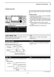
...;DEF] [EXIT/SET] Main dial • Keyer set mode screen This set mode is used to set the memory keyer repeat time, dash weight, paddle specifications, keyer type, etc. • Setting contents q During CW mode operation, push [F-3•KEYER] to normal screen. t Push [EXIT/SET] twice to select memory keyer screen...
...;DEF] [EXIT/SET] Main dial • Keyer set mode screen This set mode is used to set the memory keyer repeat time, dash weight, paddle specifications, keyer type, etc. • Setting contents q During CW mode operation, push [F-3•KEYER] to normal screen. t Push [EXIT/SET] twice to select memory keyer screen...

Instruction Manual
Page 190
SPECIFICATIONS AND OPTIONS Section 15 I Specifications 15-2 D General 15-2 D Transmitter 15-2 D Receiver 15-3 D Antenna tuner 15-3 I Options 15-4 15-1
SPECIFICATIONS AND OPTIONS Section 15 I Specifications 15-2 D General 15-2 D Transmitter 15-2 D Receiver 15-3 D Antenna tuner 15-3 I Options 15-4 15-1
Instruction Manual
Page 191
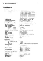
after from turn the main power, [I Specifications D General • Frequency coverage (unit: MHz) Receiver Transmitter • Operating mode • Number of memory channels • Antenna connector • Operating temperature range &#...8226; Frequency stability • Frequency resolution • Power supply requirement • Power consumption Power OFF Stand-by Receive Stand-by Max. 15 SPECIFICATIONS AND OPTIONS I /O], ON, 0-50˚C; 32-122˚F) : 1 Hz : 85-265 V AC (universal input) : 10 VA typical 200 VA typical 210 VA typical...
after from turn the main power, [I Specifications D General • Frequency coverage (unit: MHz) Receiver Transmitter • Operating mode • Number of memory channels • Antenna connector • Operating temperature range &#...8226; Frequency stability • Frequency resolution • Power supply requirement • Power consumption Power OFF Stand-by Receive Stand-by Max. 15 SPECIFICATIONS AND OPTIONS I /O], ON, 0-50˚C; 32-122˚F) : 1 Hz : 85-265 V AC (universal input) : 10 VA typical 200 VA typical 210 VA typical...

Instruction Manual
Page 192
Spurious signals may have cosmetic imperfections that appear as small or dark spots. All stated specifications are typical and subject to 125 Ω unbalanced (50 MHz band; They are made in the internal circuit and does not indicate a ... are made in the scope circuit. This does not indicate a transceiver malfunction. VSWR better than 3:1) 20 to change without notice or obligation. 15-3 15 SPECIFICATIONS AND OPTIONS D Receiver • Receive system : Double conversion superheterodyne system • Intermediate frequencies : 1st 64.455 MHz (MAIN band) 64.555 MHz ...
Spurious signals may have cosmetic imperfections that appear as small or dark spots. All stated specifications are typical and subject to 125 Ω unbalanced (50 MHz band; They are made in the internal circuit and does not indicate a ... are made in the scope circuit. This does not indicate a transceiver malfunction. VSWR better than 3:1) 20 to change without notice or obligation. 15-3 15 SPECIFICATIONS AND OPTIONS D Receiver • Receive system : Double conversion superheterodyne system • Intermediate frequencies : 1st 64.455 MHz (MAIN band) 64.555 MHz ...
Instruction Manual
Page 193
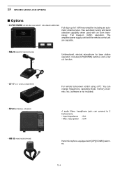
...operating mode, memory channels, etc. (software is not included) 4 audio filters; headphone jack; input power : 5 W Hand microphone equipped with an Icom transceiver. You can connect to 2 transceivers. • Input impedance : 8 Ω • Max. Has automatic tuning and band selection capability when...CONVERTER • SP-20 EXTERNAL SPEAKER • HM-36 HAND MICROPHONE For remote transceiver control using a PC. 15 SPECIFICATIONS AND OPTIONS I Options • IC-PW1/EURO HF/50 MHz ALL BAND 1 kW LINEAR AMPLIFIER Full-duty-cycle 1 kW linear amplifier including an automatic ...
...operating mode, memory channels, etc. (software is not included) 4 audio filters; headphone jack; input power : 5 W Hand microphone equipped with an Icom transceiver. You can connect to 2 transceivers. • Input impedance : 8 Ω • Max. Has automatic tuning and band selection capability when...CONVERTER • SP-20 EXTERNAL SPEAKER • HM-36 HAND MICROPHONE For remote transceiver control using a PC. 15 SPECIFICATIONS AND OPTIONS I Options • IC-PW1/EURO HF/50 MHz ALL BAND 1 kW LINEAR AMPLIFIER Full-duty-cycle 1 kW linear amplifier including an automatic ...