Instruction Manual
Page 5
... 2-6 D Rear panel-1 2-6 D Rear panel-2 2-7 ■ Linear amplifier connections 2-8 D Connecting the IC-PW1/EURO 2-8 D Connecting a non-Icom linear amplifier 2-8 ■ Transverter jack information 2-9 ■ FSK and AFSK (SSTV) connections 2-9 ■...; Microphone connector information 2-10 ■ Microphones (options 2-10 D SM-20 2-10 D HM-36 2-10 ■ Accessory connector information 2-11 BASIC OPERATIONS ■ When first applying power (CPU resetting...
... 2-6 D Rear panel-1 2-6 D Rear panel-2 2-7 ■ Linear amplifier connections 2-8 D Connecting the IC-PW1/EURO 2-8 D Connecting a non-Icom linear amplifier 2-8 ■ Transverter jack information 2-9 ■ FSK and AFSK (SSTV) connections 2-9 ■...; Microphone connector information 2-10 ■ Microphones (options 2-10 D SM-20 2-10 D HM-36 2-10 ■ Accessory connector information 2-11 BASIC OPERATIONS ■ When first applying power (CPU resetting...

Instruction Manual
Page 10
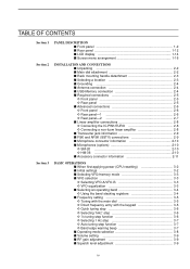
TABLE OF CONTENTS ■ Fuse replacement 13-7 ■ Resetting the CPU 13-7 ■ About protection indications 13-8 ■ Screen saver function 13-8 Section 14 CONTROL COMMAND ■ Remote jack (CI-V) information 14-2 D CI-V connection ...
TABLE OF CONTENTS ■ Fuse replacement 13-7 ■ Resetting the CPU 13-7 ■ About protection indications 13-8 ■ Screen saver function 13-8 Section 14 CONTROL COMMAND ■ Remote jack (CI-V) information 14-2 D CI-V connection ...

Instruction Manual
Page 39
BASIC OPERATIONS Section 3 ■ When first applying power (CPU resetting 3-2 ■ Initial settings 3-2 ■ Selecting VFO/memory mode 3-3 ■ VFO selection 3-3 D Selecting VFO-A/VFO-B 3-3 D VFO equalization 3-3 ■ Selecting an operating band 3-4 D Using the band stacking ...
BASIC OPERATIONS Section 3 ■ When first applying power (CPU resetting 3-2 ■ Initial settings 3-2 ■ Selecting VFO/memory mode 3-3 ■ VFO selection 3-3 D Selecting VFO-A/VFO-B 3-3 D VFO equalization 3-3 ■ Selecting an operating band 3-4 D Using the band stacking ...
Instruction Manual
Page 40
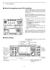
... the rear panel. • The transceiver power is normal and does not indicate any equipment malfunction. ■ Initial settings After resetting the transceiver, set controls as shown in set mode settings after turning power ON. This is still OFF and the power indicator ...lights orange. clockwise [RF] : Max. clockwise [AF] : Max. 3 BASIC OPERATIONS ■ When first applying power (CPU resetting) Before first applying power, make sure all programmed contents in memory channels and returns programmed values in the figure below. [KEY SPEED] : 10-12...
... the rear panel. • The transceiver power is normal and does not indicate any equipment malfunction. ■ Initial settings After resetting the transceiver, set controls as shown in set mode settings after turning power ON. This is still OFF and the power indicator ...lights orange. clockwise [RF] : Max. clockwise [AF] : Max. 3 BASIC OPERATIONS ■ When first applying power (CPU resetting) Before first applying power, make sure all programmed contents in memory channels and returns programmed values in the figure below. [KEY SPEED] : 10-12...

Instruction Manual
Page 62
... desired condition using the main dial. • Push and hold [001CLR] F-4 for contest (serial) numbers- e Push [Y] F-1 or [Z] F-2 to select the default condition or value. to reset the current number to normal screen. Normal • Normal : Does not use short morse numbers (default) • 190➔ANO : Sets 1 as A, 9 as N and 0 as...
... desired condition using the main dial. • Push and hold [001CLR] F-4 for contest (serial) numbers- e Push [Y] F-1 or [Z] F-2 to select the default condition or value. to reset the current number to normal screen. Normal • Normal : Does not use short morse numbers (default) • 190➔ANO : Sets 1 as A, 9 as N and 0 as...

Instruction Manual
Page 98
... of the received station. RIT CLEAR D RIT monitor function XFC When the RIT function is ON, pushing and holding [XFC] allows you to reset the RIT frequency when the quick RIT/∂TX clear function is temporarily cancelled). ✔ For your convenience- to add the shift frequency to ...turn the RIT function ON and OFF. • " RIT " and the shifting frequency appear when the function is ON. to reset the RIT frequency. • Push CLEAR momentarily to monitor the operating frequency directly (RIT is ON. (p. 12-15) • Push and hold RIT for...
... of the received station. RIT CLEAR D RIT monitor function XFC When the RIT function is ON, pushing and holding [XFC] allows you to reset the RIT frequency when the quick RIT/∂TX clear function is temporarily cancelled). ✔ For your convenience- to add the shift frequency to ...turn the RIT function ON and OFF. • " RIT " and the shifting frequency appear when the function is ON. to reset the RIT frequency. • Push CLEAR momentarily to monitor the operating frequency directly (RIT is ON. (p. 12-15) • Push and hold RIT for...

Instruction Manual
Page 112
... ∂TX frequency, push and hold ∂TX for 1 sec. w Rotate [MONI GAIN] for 1 sec. • Push CLEAR momentarily to reset the ∂TX frequency when the quick RIT/∂TX clear function is ON. (p. 12-15) r To cancel the ∂TX function, push ∂TX ...
... ∂TX frequency, push and hold ∂TX for 1 sec. w Rotate [MONI GAIN] for 1 sec. • Push CLEAR momentarily to reset the ∂TX frequency when the quick RIT/∂TX clear function is ON. (p. 12-15) r To cancel the ∂TX function, push ∂TX ...

Instruction Manual
Page 158
... default value, '0.' 0 0 12-4 NOTE: When this setting is active, below 2 items will be reset to default value, '0.' 0 0 --- - --- 12 SET MODE ■ Level set mode SSB RX HPF/LPF Sets the low-pass filter (100 Hz to 2000 Hz) and ... the treble level of the receive audio tone in FM mode from -5 to default value, '0.' 0 0 --- - --- NOTE: When this setting is active, below 2 items will be reset to +5. (default: 0) --- - ---
... default value, '0.' 0 0 12-4 NOTE: When this setting is active, below 2 items will be reset to default value, '0.' 0 0 --- - --- 12 SET MODE ■ Level set mode SSB RX HPF/LPF Sets the low-pass filter (100 Hz to 2000 Hz) and ... the treble level of the receive audio tone in FM mode from -5 to default value, '0.' 0 0 --- - --- NOTE: When this setting is active, below 2 items will be reset to +5. (default: 0) --- - ---

Instruction Manual
Page 181
MAINTENANCE Section 13 ■ Troubleshooting 13-2 D Transceiver power 13-2 D Transmit and receive 13-2 D Scanning 13-3 D Display 13-3 D Format USB-Memory 13-3 ■ Main dial brake adjustment 13-3 ■ SWR reading 13-4 ■ Screen type and font selections 13-4 ■ Frequency calibration (approximate 13-5 ■ Opening the transceiver's case 13-6 ■ Clock backup battery replacement 13-6 ■ Fuse replacement 13-7 ■ Resetting the CPU 13-7 ■ About protection indications 13-8 ■ Screen Saver Function 13-8 13-1
MAINTENANCE Section 13 ■ Troubleshooting 13-2 D Transceiver power 13-2 D Transmit and receive 13-2 D Scanning 13-3 D Display 13-3 D Format USB-Memory 13-3 ■ Main dial brake adjustment 13-3 ■ SWR reading 13-4 ■ Screen type and font selections 13-4 ■ Frequency calibration (approximate 13-5 ■ Opening the transceiver's case 13-6 ■ Clock backup battery replacement 13-6 ■ Fuse replacement 13-7 ■ Resetting the CPU 13-7 ■ About protection indications 13-8 ■ Screen Saver Function 13-8 13-1
Instruction Manual
Page 182
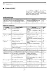
...unclear • [MIC] is set too far clockwise or distorted. • Set [MIC] to select "ATT p. 5-9 OFF." only strong signals are not equipment malfunctions. to reset the p. 5-12 function. • Noise blanker is turned ON when receiving a • Push [NB] to turn the p. 5-9 function OFF. • The noise reduction is... set mode. is pushed. • Circuit breaker is improperly connected. 13 MAINTENANCE ■ Troubleshooting The following chart is designed to help you nearest Icom Dealer or Service Center. p. 3-12 • Set [DRIVE] to a suitable position.
...unclear • [MIC] is set too far clockwise or distorted. • Set [MIC] to select "ATT p. 5-9 OFF." only strong signals are not equipment malfunctions. to reset the p. 5-12 function. • Noise blanker is turned ON when receiving a • Push [NB] to turn the p. 5-9 function OFF. • The noise reduction is... set mode. is pushed. • Circuit breaker is improperly connected. 13 MAINTENANCE ■ Troubleshooting The following chart is designed to help you nearest Icom Dealer or Service Center. p. 3-12 • Set [DRIVE] to a suitable position.
Instruction Manual
Page 183
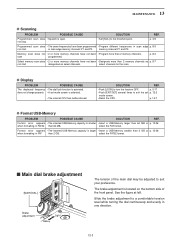
.... See the figure at left. not stop. • Set [SQL] to turn the function OFF. does not change properly. • A set p. 12-2 mode screen. • Reset the CPU. p. 13-7 D Format USB-Memory PROBLEM POSSIBLE CAUSE SOLUTION REF. in one direction. 13-3 Memory scan does not • 2 or more memory channels have...
.... See the figure at left. not stop. • Set [SQL] to turn the function OFF. does not change properly. • A set p. 12-2 mode screen. • Reset the CPU. p. 13-7 D Format USB-Memory PROBLEM POSSIBLE CAUSE SOLUTION REF. in one direction. 13-3 Memory scan does not • 2 or more memory channels have...

Instruction Manual
Page 187
...cover and screws to default values. ALL CLEAR 13-7 q Remove the bottom cover as shown at left . e Replace the open . NOTE: Resetting CLEARS all programmed contents in memory channels and returns programmed values in this case. w Remove the 8 screws from the AC outlet before removing the...INPENT and MW , push POWER to turn power ON. • The internal CPU is reset. • The CPU start-up takes approx. 5 sec. • The transceiver displays its initial VFO frequencies when resetting is complete. ■ Fuse replacement MAINTENANCE 13 When no external DC output is available ...
...cover and screws to default values. ALL CLEAR 13-7 q Remove the bottom cover as shown at left . e Replace the open . NOTE: Resetting CLEARS all programmed contents in memory channels and returns programmed values in this case. w Remove the 8 screws from the AC outlet before removing the...INPENT and MW , push POWER to turn power ON. • The internal CPU is reset. • The CPU start-up takes approx. 5 sec. • The transceiver displays its initial VFO frequencies when resetting is complete. ■ Fuse replacement MAINTENANCE 13 When no external DC output is available ...


