Instruction Manual
Page 3
... or bottom of time. R CAUTION! ally desire to carry, lift or turn the transceiver power OFF and remove the power cable if it emits an abnormal odor, sound or smoke. Use Icom microphones only (supplied or optional). During maritime mobile operation, keep the transceiver and microphone as far away as output power, idling current, etc., might damage the expensive final devices. NEVER operate the transceiver with a headset or other ob...
... or bottom of time. R CAUTION! ally desire to carry, lift or turn the transceiver power OFF and remove the power cable if it emits an abnormal odor, sound or smoke. Use Icom microphones only (supplied or optional). During maritime mobile operation, keep the transceiver and microphone as far away as output power, idling current, etc., might damage the expensive final devices. NEVER operate the transceiver with a headset or other ob...
Instruction Manual
Page 12
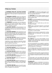
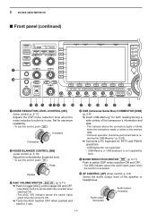
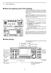
... [POWER] indicator lights orange when the transceiver is OFF when the internal power supply is open. e ANTENNA TUNER SWITCH TUNER (p. 10-6) ➥ Turns the internal antenna tuner ON and OFF (bypass) when pushed momentarily. • The [TUNER] indicator above this switch lights green when the timer is in keyer set mode when pushed and held for 1 sec. • The [TUNER] indicator blinks red during manual tuning...
... [POWER] indicator lights orange when the transceiver is OFF when the internal power supply is open. e ANTENNA TUNER SWITCH TUNER (p. 10-6) ➥ Turns the internal antenna tuner ON and OFF (bypass) when pushed momentarily. • The [TUNER] indicator above this switch lights green when the timer is in keyer set mode when pushed and held for 1 sec. • The [TUNER] indicator blinks red during manual tuning...
Instruction Manual
Page 13
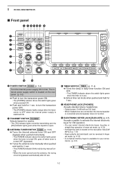
... Squelch threshold Noise squelch Shallow Squelch is particularly effective for 1 sec. Recommended level for the most effective use [AGC] control, push AGC VR ([AGC VR] indicator lights). Full break-in (QSK) can be adjusted independently in set mode. (p. 12-5) ✔ How to enter VOX set the microphone gain. i MIC GAIN CONTROL [MIC] (p. 3-12) Adjusts microphone input gain. • The transmit audio tone in SSB, AM and FM modes can monitor the receive...
... Squelch threshold Noise squelch Shallow Squelch is particularly effective for 1 sec. Recommended level for the most effective use [AGC] control, push AGC VR ([AGC VR] indicator lights). Full break-in (QSK) can be adjusted independently in set mode. (p. 12-5) ✔ How to enter VOX set the microphone gain. i MIC GAIN CONTROL [MIC] (p. 3-12) Adjusts microphone input gain. • The transmit audio tone in SSB, AM and FM modes can monitor the receive...
Instruction Manual
Page 14
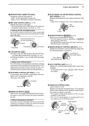
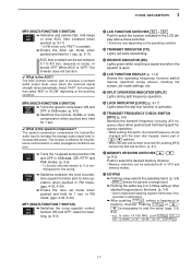
...* are supported. *: USB-Memory or USB keyboard is not supplied by Icom. @1 NOISE REDUCTION SWITCH NR (p. 5-17) Push to the memory data. • Unmount operation should be performed before removing the USB-Memory* (p.12-25). ➥ Connects a PC keyboard for maximum readability. • To use this switch lights green when the function is in use. p. 3-9) Varies the audio output level of the transceiver's information...
...* are supported. *: USB-Memory or USB keyboard is not supplied by Icom. @1 NOISE REDUCTION SWITCH NR (p. 5-17) Push to the memory data. • Unmount operation should be performed before removing the USB-Memory* (p.12-25). ➥ Connects a PC keyboard for maximum readability. • To use this switch lights green when the function is in use. p. 3-9) Varies the audio output level of the transceiver's information...
Instruction Manual
Page 17
... on the operating condition. #5 TRANSMIT INDICATOR [TX] Lights red while transmitting. #6 RECEIVE INDICATOR [RX] Lights green while receiving a signal and when the squelch is open. #7 LCD FUNCTION DISPLAY (p. 1-14) Shows the operating frequency, function switch menus, spectrum scope screen, memory list screen, set mode settings, etc. #8 SPLIT OPERATION INDICATOR [SPLIT] Lights during split frequency operation. #9 LOCK INDICATOR [LOCK] (p. 5-17) Lights when the dial lock function is activated. $0 TRANSMIT FREQUENCY CHECK SWITCH [XFC] (p. 6-6) Monitors the transmit frequency (including ∂...
... on the operating condition. #5 TRANSMIT INDICATOR [TX] Lights red while transmitting. #6 RECEIVE INDICATOR [RX] Lights green while receiving a signal and when the squelch is open. #7 LCD FUNCTION DISPLAY (p. 1-14) Shows the operating frequency, function switch menus, spectrum scope screen, memory list screen, set mode settings, etc. #8 SPLIT OPERATION INDICATOR [SPLIT] Lights during split frequency operation. #9 LOCK INDICATOR [LOCK] (p. 5-17) Lights when the dial lock function is activated. $0 TRANSMIT FREQUENCY CHECK SWITCH [XFC] (p. 6-6) Monitors the transmit frequency (including ∂...
Instruction Manual
Page 25
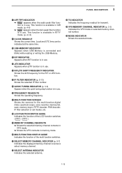
... the frequency readout for the multi-function digital meter, spectrum scope, voice recorder, memory list, scan, memory keyer, RTTY decoder, PSK decoder, IF filter selection or set modes, etc. !8 LCD FUNCTION SWITCH GUIDE Indicates the function of the multi-function switches. @1 SELECT MEMORY CHANNEL INDICATOR (p. 9-7) Indicates the displayed memory channel is available in RTTY mode. (p. 4-14) o CLOCK READOUT Shows the current time. F-7 ). !9 MEMORY CHANNEL...
... the frequency readout for the multi-function digital meter, spectrum scope, voice recorder, memory list, scan, memory keyer, RTTY decoder, PSK decoder, IF filter selection or set modes, etc. !8 LCD FUNCTION SWITCH GUIDE Indicates the function of the multi-function switches. @1 SELECT MEMORY CHANNEL INDICATOR (p. 9-7) Indicates the displayed memory channel is available in RTTY mode. (p. 4-14) o CLOCK READOUT Shows the current time. F-7 ). !9 MEMORY CHANNEL...
Instruction Manual
Page 30
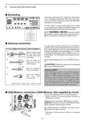
... operation is not supplied by using a single antenna, use the [ANT1] connector. The IC-7700 has an SWR meter to monitor the antenna SWR continuously. ■ USB-Memory connection (USB-Memory: Not supplied by Icom) Connect the USB-Memory* to protect the final transistors. Strip the cable jacket and 10 mm (soft solder) tin the braid. Low SWR allows full power for a specified frequency range and...
... operation is not supplied by using a single antenna, use the [ANT1] connector. The IC-7700 has an SWR meter to monitor the antenna SWR continuously. ■ USB-Memory connection (USB-Memory: Not supplied by Icom) Connect the USB-Memory* to protect the final transistors. Strip the cable jacket and 10 mm (soft solder) tin the braid. Low SWR allows full power for a specified frequency range and...
Instruction Manual
Page 40
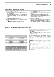
... resetting the transceiver, set controls as shown in set mode settings after turning power ON. counter clockwise [MIC] : 10-12 o'clock [RF PWR] : Max. clockwise POWER HF/50MHz TRANSCEIVER i7700 TRANSMIT TUNER VOX BK-IN MONITOR MIC RF PWR KEY SPEED DELAY TIMER PHONES AGC SQL NR NB ELEC-KEY MIC AGC VR NR AF NB RF DRIVE TX RX SPLIT LOCK 1.8 1 10 4 21 7 GENE XFC 3.5 2 14...
... resetting the transceiver, set controls as shown in set mode settings after turning power ON. counter clockwise [MIC] : 10-12 o'clock [RF PWR] : Max. clockwise POWER HF/50MHz TRANSCEIVER i7700 TRANSMIT TUNER VOX BK-IN MONITOR MIC RF PWR KEY SPEED DELAY TIMER PHONES AGC SQL NR NB ELEC-KEY MIC AGC VR NR AF NB RF DRIVE TX RX SPLIT LOCK 1.8 1 10 4 21 7 GENE XFC 3.5 2 14...
Instruction Manual
Page 50
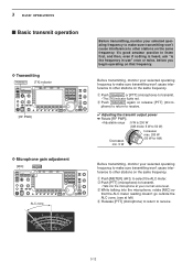
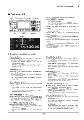
... [PTT] (microphone) to return to receive. ✔ Adjusting the transmit output power ➥ Rotate [RF PWR]. • Adjustable range : 5 W to 200 W (AM mode: 5 W to 50 W) Decreases min. 5 W Increases max. 200 W (50 W for AM) Before transmitting, monitor your selected operating frequency to make sure transmitting won't cause interference to other stations on the same frequency. q Push [METER] (MF2) to transmit. • The [TX] indicator lights red. w Push [PTT] (microphone) to transmit. • Talk into the microphone, rotate [MIC...
... [PTT] (microphone) to return to receive. ✔ Adjusting the transmit output power ➥ Rotate [RF PWR]. • Adjustable range : 5 W to 200 W (AM mode: 5 W to 50 W) Decreases min. 5 W Increases max. 200 W (50 W for AM) Before transmitting, monitor your selected operating frequency to make sure transmitting won't cause interference to other stations on the same frequency. q Push [METER] (MF2) to transmit. • The [TX] indicator lights red. w Push [PTT] (microphone) to transmit. • Talk into the microphone, rotate [MIC...
Instruction Manual
Page 54
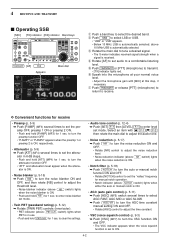
... AGC VR to turn the AGC time constant manual setting ON and OFF. • Rotate [AGC] control to adjust the time constant. • VSC (voice squelch control) (p. 9-3) ➥ Push [VSC] (MF7) to turn the auto or manual notch function ON and OFF. • Rotate [NOTCH] control to set the pre- 4 RECEIVE AND TRANSMIT ■ Operating SSB [MIC] [TX] indicator [RX] indicator Band keys TRANSMIT [AF] SSB...
... AGC VR to turn the AGC time constant manual setting ON and OFF. • Rotate [AGC] control to adjust the time constant. • VSC (voice squelch control) (p. 9-3) ➥ Push [VSC] (MF7) to turn the auto or manual notch function ON and OFF. • Rotate [NOTCH] control to set the pre- 4 RECEIVE AND TRANSMIT ■ Operating SSB [MIC] [TX] indicator [RX] indicator Band keys TRANSMIT [AF] SSB...
Instruction Manual
Page 55
... transceiver to turn the monitor function ON and OFF. • Rotate [MONI GAIN] to enter level set all controls so that you in the table above. D About 5 MHz band operation (USA version only) Operation on the 5 MHz band is allowed on 5 discrete frequencies and must adhere to the following: • USB mode • Maximum of 50 watts ERP (Effective Radiated Power) • 2.8 kHz bandwidth IC-7700 Displayed Frequency...
... transceiver to turn the monitor function ON and OFF. • Rotate [MONI GAIN] to enter level set all controls so that you in the table above. D About 5 MHz band operation (USA version only) Operation on the 5 MHz band is allowed on 5 discrete frequencies and must adhere to the following: • USB mode • Maximum of 50 watts ERP (Effective Radiated Power) • 2.8 kHz bandwidth IC-7700 Displayed Frequency...
Instruction Manual
Page 63
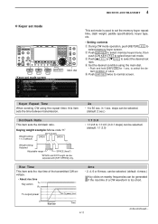
... sec. steps can be selected. (default: 1:1:3.0) Rise Time This item sets the rise time of a CW waveform is used to set the memory keyer repeat time, dash weight, paddle specifications, keyer type, etc. • Setting contents q During CW mode operation, push [KEYER] F-3 to 1:1:4.5 (in 1 sec. Keying weight example: Morse code "K" Weight setting: 1:1:3 (default) DOT (fixed*) DASH DASH Weight setting: Adjusted Adjustable range SPACE (fixed*) *SPACE and DOT length can be...
... sec. steps can be selected. (default: 1:1:3.0) Rise Time This item sets the rise time of a CW waveform is used to set the memory keyer repeat time, dash weight, paddle specifications, keyer type, etc. • Setting contents q During CW mode operation, push [KEYER] F-3 to 1:1:4.5 (in 1 sec. Keying weight example: Morse code "K" Weight setting: 1:1:3 (default) DOT (fixed*) DASH DASH Weight setting: Adjusted Adjustable range SPACE (fixed*) *SPACE and DOT length can be...
Instruction Manual
Page 69
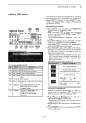
... RTTY memory channel to be set using the memory edit menu. Key selection Editable characters ABC A to Z (capital letters) a to z (small letters) abc (selectable for often-used RTTY information. 4 RECEIVE AND TRANSMIT D Editing RTTY memory 123 / Symbol ABC / abc DEL SPACE F-3 F-4 Ω ≈ F-1 F-2 Ω ≈ EXIT/SET RT1..RT8 F-5 F-7 • RTTY memory edit screen • Pre-programmed contents CH...
... RTTY memory channel to be set using the memory edit menu. Key selection Editable characters ABC A to Z (capital letters) a to z (small letters) abc (selectable for often-used RTTY information. 4 RECEIVE AND TRANSMIT D Editing RTTY memory 123 / Symbol ABC / abc DEL SPACE F-3 F-4 Ω ≈ F-1 F-2 Ω ≈ EXIT/SET RT1..RT8 F-5 F-7 • RTTY memory edit screen • Pre-programmed contents CH...
Instruction Manual
Page 81
.... • Audio tone control (p. 12-4) ➥ Push [SET] F-7 then [LEVEL] F-1 to a comfortable listening level. t Push TRANSMIT or [PTT] (microphone) to turn the noise reduction ON and OFF. • Rotate [NR] control to adjust the noise reduction level. • Noise reduction indicator (above PBT-CLR switch) lights when PBT is ON. • Push and hold [ATT] (MF3) for 1 sec. to turn the AGC time constant manual setting ON...
.... • Audio tone control (p. 12-4) ➥ Push [SET] F-7 then [LEVEL] F-1 to a comfortable listening level. t Push TRANSMIT or [PTT] (microphone) to turn the noise reduction ON and OFF. • Rotate [NR] control to adjust the noise reduction level. • Noise reduction indicator (above PBT-CLR switch) lights when PBT is ON. • Push and hold [ATT] (MF3) for 1 sec. to turn the AGC time constant manual setting ON...
Instruction Manual
Page 106
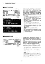
... in CW, RTTY, PSK modes. ➥ Push NOTCH to turn the auto notch function ON and OFF in use . • " MN " appears when manual notch is activated, mechanical noise may be set to 29.999999 MHz range. The available frequency is activated. 5-18 The auto notch function uses DSP to automatically attenuate up to the switching noise from strong signals near the received frequency.
... in CW, RTTY, PSK modes. ➥ Push NOTCH to turn the auto notch function ON and OFF in use . • " MN " appears when manual notch is activated, mechanical noise may be set to 29.999999 MHz range. The available frequency is activated. 5-18 The auto notch function uses DSP to automatically attenuate up to the switching noise from strong signals near the received frequency.
Instruction Manual
Page 130
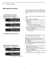
... either VFO mode or memory mode. This is useful for transferring frequency and operating mode while operating in memory mode. quency and operating mode. • Transferred frequency and operating mode appear on the frequency readout. to VFO mode, push V/M momentarily. When you have changed the frequency or operating mode in the selected memory channel: • Displayed frequency, mode and filter setting are transferred. • Programmed frequency and mode in the memory channel. q Select the memory channel to be transferred...
... either VFO mode or memory mode. This is useful for transferring frequency and operating mode while operating in memory mode. quency and operating mode. • Transferred frequency and operating mode appear on the frequency readout. to VFO mode, push V/M momentarily. When you have changed the frequency or operating mode in the selected memory channel: • Displayed frequency, mode and filter setting are transferred. • Programmed frequency and mode in the memory channel. q Select the memory channel to be transferred...
Instruction Manual
Page 149
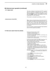
... is changed (more than 3:1 for 50 MHz band) • the power source voltage/capacity. D If the tuner cannot tune the antenna Check the following : • repeat manual tuning several times. • tune with each antenna tuner for the first transmission on a new frequency. Less than 1.5:1 after the frequency is completed, turn OFF the IC-7700's tuner. This function replaces the "push and hold TUNER " operation and...
... is changed (more than 3:1 for 50 MHz band) • the power source voltage/capacity. D If the tuner cannot tune the antenna Check the following : • repeat manual tuning several times. • tune with each antenna tuner for the first transmission on a new frequency. Less than 1.5:1 after the frequency is completed, turn OFF the IC-7700's tuner. This function replaces the "push and hold TUNER " operation and...
Instruction Manual
Page 176
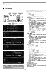
...connected to select setting save option set menu screen. q During set mode settings, etc. OPTION F-5 SAVE / OK F-6 WIDE / CANCEL F-7 DIR/FILE EDIT EXIT/SET F-1 F-4 Main dial When a PC keyboard is completed, return to select the file name, if necessary. r Push [SAVE] F-6 . • Confirmation screen appears. to select the file name. 12 SET MODE ■ File saving Memory channel contents, set mode menu... (numerals); [Symbol] (MF7 can also be saved into the USB-Memory for 1 sec. to making a new folder. (Edit the name with the same manner as the "• File name" above.) c...
...connected to select setting save option set menu screen. q During set mode settings, etc. OPTION F-5 SAVE / OK F-6 WIDE / CANCEL F-7 DIR/FILE EDIT EXIT/SET F-1 F-4 Main dial When a PC keyboard is completed, return to select the file name, if necessary. r Push [SAVE] F-6 . • Confirmation screen appears. to select the file name. 12 SET MODE ■ File saving Memory channel contents, set mode menu... (numerals); [Symbol] (MF7 can also be saved into the USB-Memory for 1 sec. to making a new folder. (Edit the name with the same manner as the "• File name" above.) c...
Instruction Manual
Page 182
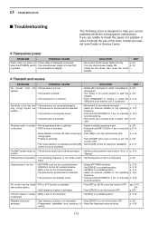
...] to to turn the function ON • Programmed subaudible tone frequency is • Reset the frequency using set the circuit - p. 2-5 • Turn the internal power supply ON. SOLUTION REF. • Rotate [AF] clockwise to manually p. 10-6 tune the antenna. Received audio is unclear • Wrong operating mode is activated. D Transceiver power PROBLEM POSSIBLE CAUSE Power does not come on • Power cable is selected. SOLUTION REF. • Re-connect the AC power cable correctly. only...
...] to to turn the function ON • Programmed subaudible tone frequency is • Reset the frequency using set the circuit - p. 2-5 • Turn the internal power supply ON. SOLUTION REF. • Rotate [AF] clockwise to manually p. 10-6 tune the antenna. Received audio is unclear • Wrong operating mode is activated. D Transceiver power PROBLEM POSSIBLE CAUSE Power does not come on • Power cable is selected. SOLUTION REF. • Re-connect the AC power cable correctly. only...
Instruction Manual
Page 210
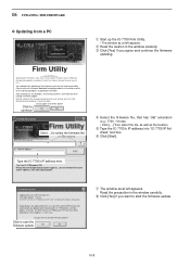
... NOT turn the IC-7700 power OFF until the normal operational screen appears, in such case. i Click [Yes] if you want to start the firmware update? 16 UPDATING THE FIRMWARE D Updating from a PC i7700 HF/50MHz TRANSCEIVER q Start up the IC-7700 Firm Utility. • The window as at you own risk and responsibility, Please refer to the firmware download homepage and/or the instruction manual for...
... NOT turn the IC-7700 power OFF until the normal operational screen appears, in such case. i Click [Yes] if you want to start the firmware update? 16 UPDATING THE FIRMWARE D Updating from a PC i7700 HF/50MHz TRANSCEIVER q Start up the IC-7700 Firm Utility. • The window as at you own risk and responsibility, Please refer to the firmware download homepage and/or the instruction manual for...


