
Instruction Manual
Page 2
... amplifier is connected, set the transceiver's RF output power to rain, snow or any internal part or connectors on the rear panel of the IC-718 which display the "CE" symbol on the serial number seal comply with temperatures below -10°C (+14°F) or above +60°C...or putting anything on the transceiver rear panel. During mobile operation, DO NOT operate the transceiver without running the vehicle's engine. Use Icom microphones only (supplied or optional). NEVER attach an antenna or internal antenna connector during transmission. When transceiver power is ON and your ...
... amplifier is connected, set the transceiver's RF output power to rain, snow or any internal part or connectors on the rear panel of the IC-718 which display the "CE" symbol on the serial number seal comply with temperatures below -10°C (+14°F) or above +60°C...or putting anything on the transceiver rear panel. During mobile operation, DO NOT operate the transceiver without running the vehicle's engine. Use Icom microphones only (supplied or optional). NEVER attach an antenna or internal antenna connector during transmission. When transceiver power is ON and your ...
Instruction Manual
Page 13
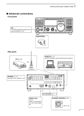
... for computer control and transceive operation. 3 INSTALLATION AND CONNECTIONS s Advanced connections • Front panel MIC The AFSK modulation signal can be input from [MIC]. (p. 33) IC-718 MODE FIL TS PWR AF RF/SQL RIT SHIFT MIC PHONES LOCK 1 2 3 V/M A=B A/B 4 5 6 MW M - CL ∫ M V 7 8 9 SPL SCN VOX . 0 NR ANF F-INP ENT NB COMP SET... ∫ HEADPHONES • Rear panel AH-4 (p. 55) with AH-2b or long wire ANTENNA (p. 13) Connects a liner amprifier, etc. [REMOTE] (p. 57) Used for connecting a non-Icom linear amplifier.
... for computer control and transceive operation. 3 INSTALLATION AND CONNECTIONS s Advanced connections • Front panel MIC The AFSK modulation signal can be input from [MIC]. (p. 33) IC-718 MODE FIL TS PWR AF RF/SQL RIT SHIFT MIC PHONES LOCK 1 2 3 V/M A=B A/B 4 5 6 MW M - CL ∫ M V 7 8 9 SPL SCN VOX . 0 NR ANF F-INP ENT NB COMP SET... ∫ HEADPHONES • Rear panel AH-4 (p. 55) with AH-2b or long wire ANTENNA (p. 13) Connects a liner amprifier, etc. [REMOTE] (p. 57) Used for connecting a non-Icom linear amplifier.
Instruction Manual
Page 14
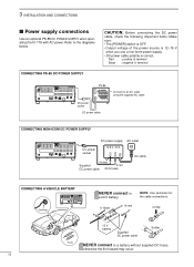
...• The [POWER] switch is OFF. • Output voltage of the power source is 12-15 V when you use a non-Icom power supply. • DC power cable polarity is correct. Red : positive + terminal Black : negative _ terminal PS-85 13 9 ... socket Connect to a 24 V battery. _ black + red NOTE: Use terminals for the cable connections. DC power cable CONNECTING NON-ICOM DC POWER SUPPLY DC power supply AC outlet DC power 13.8 V 20 A socket _+ 13 9 10 11 12 5678 1234 AC...s Power supply connections Use an optional PS-85 DC POWER SUPPLY when operating the IC-718 with AC power.
...• The [POWER] switch is OFF. • Output voltage of the power source is 12-15 V when you use a non-Icom power supply. • DC power cable polarity is correct. Red : positive + terminal Black : negative _ terminal PS-85 13 9 ... socket Connect to a 24 V battery. _ black + red NOTE: Use terminals for the cable connections. DC power cable CONNECTING NON-ICOM DC POWER SUPPLY DC power supply AC outlet DC power 13.8 V 20 A socket _+ 13 9 10 11 12 5678 1234 AC...s Power supply connections Use an optional PS-85 DC POWER SUPPLY when operating the IC-718 with AC power.
Instruction Manual
Page 16
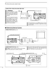
... ACC cable supplied with the AT-180 [ACC] one of two AT-180 [ACC] connectors HF antenna IC-718 13 9 10 11 12 5678 1234 Ground 14 The ALC input level must be in the range 0 V...the AH-4) Control cable IC-718 Ground Ground AH-4 CONNECTING THE AT-180 (p. 28) DO NOT! To an antenna RF OUTPUT RF INPUT SEND ALC Non-Icom linear amplifier 50 Ω coaxial cable ANT IC-718 SEND 13 9 10... 11 12 5678 1234 ALC The specifications for the SEND relay are 16 V DC 2 A. Turn the IC-718's power OFF when...
... ACC cable supplied with the AT-180 [ACC] one of two AT-180 [ACC] connectors HF antenna IC-718 13 9 10 11 12 5678 1234 Ground 14 The ALC input level must be in the range 0 V...the AH-4) Control cable IC-718 Ground Ground AH-4 CONNECTING THE AT-180 (p. 28) DO NOT! To an antenna RF OUTPUT RF INPUT SEND ALC Non-Icom linear amplifier 50 Ω coaxial cable ANT IC-718 SEND 13 9 10... 11 12 5678 1234 ALC The specifications for the SEND relay are 16 V DC 2 A. Turn the IC-718's power OFF when...
Instruction Manual
Page 49
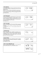
... filter selection (W/N) key combination on " when operating transceiver with the IC-718 connected to other Icom HF transceivers or receivers. The default is 5E. • CI-V Transceive Transceive operation is on the IC-718 automatically changes those of connected transceivers (or receivers) and vice versa. When ...2 or more IC-718s are FL-96, FL-222, FL-52A, FL-53A, FL-257...
... filter selection (W/N) key combination on " when operating transceiver with the IC-718 connected to other Icom HF transceivers or receivers. The default is 5E. • CI-V Transceive Transceive operation is on the IC-718 automatically changes those of connected transceivers (or receivers) and vice versa. When ...2 or more IC-718s are FL-96, FL-222, FL-52A, FL-53A, FL-257...
Instruction Manual
Page 59
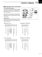
...End of message code (fixed) Preamble code (fixed) Controller's default address Transceiver's default address OK code (fixed) End of message code (fixed) IC-718 TO CONTROLLER q wert y u FE FE E0 5E Cn Sc Data area FD NG MESSAGE TO CONTROLLER FE FE E0 5E FA FD Preamble code ... End of message code (fixed) Preamble code (fixed) Controller's default address Transceiver's default address NG code (fixed) End of the transceiver. The Icom Communications Interface-V (CI-V) controls the following data formats. A data area or sub command is added for setting the CI-V condition using the following...
...End of message code (fixed) Preamble code (fixed) Controller's default address Transceiver's default address OK code (fixed) End of message code (fixed) IC-718 TO CONTROLLER q wert y u FE FE E0 5E Cn Sc Data area FD NG MESSAGE TO CONTROLLER FE FE E0 5E FA FD Preamble code ... End of message code (fixed) Preamble code (fixed) Controller's default address Transceiver's default address NG code (fixed) End of the transceiver. The Icom Communications Interface-V (CI-V) controls the following data formats. A data area or sub command is added for setting the CI-V condition using the following...


