

Instruction Manual
Page 3
... 8 3 INSTALLATION AND CONNECTIONS ......... 9 - 14 s Unpacking 9 s Selecting a location 9 s Grounding 9 s Antenna connection 9 s Required connections 10 s Advanced connections 11 s Power supply connections 12 s Liner amplifier connections 13 s External antenna tuners 14 4 FREQUENCY SETTING 15 - 19 s When first applying...25 s Function for transmit 26 s Split frequency operation 30 s SWR 30 s Function for CW 31 s Function for DC cable 1 r Fuse (FGB 4 A; q DC power cable 1 w Hand microphone (HM-36 1 e Fuse (FGB 20 A; for RTTY 33 6 MEMORY OPERATION 35 - 38 s...
... 8 3 INSTALLATION AND CONNECTIONS ......... 9 - 14 s Unpacking 9 s Selecting a location 9 s Grounding 9 s Antenna connection 9 s Required connections 10 s Advanced connections 11 s Power supply connections 12 s Liner amplifier connections 13 s External antenna tuners 14 4 FREQUENCY SETTING 15 - 19 s When first applying...25 s Function for transmit 26 s Split frequency operation 30 s SWR 30 s Function for CW 31 s Function for DC cable 1 r Fuse (FGB 4 A; q DC power cable 1 w Hand microphone (HM-36 1 e Fuse (FGB 20 A; for RTTY 33 6 MEMORY OPERATION 35 - 38 s...
Instruction Manual
Page 8
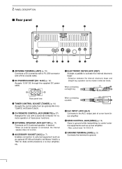
... such as a liner amplifier. • Max. r CI-V REMOTE CONTROL JACK [REMOTE] (p. 57) Designed for use with a PL-259 connector and a 50 Ω coaxial cable. u ELECTRONIC KEYER JACK [KEY] Accepts a paddle to ground. 6 2 PANEL DESCRIPTION s Rear panel q w e 13 9 10 11 12 5678 1234 !0 oi u y tr q ...ANTENNA TERMINAL [ANT] (p. 10) Connects a 50 Ω antenna with a personal computer for remote operation of a non-Icom linear amplifier. w DC POWER SOCKET [DC 13.8V] (p. 12) Accepts 13.8V DC through the supplied DC power cable.
... such as a liner amplifier. • Max. r CI-V REMOTE CONTROL JACK [REMOTE] (p. 57) Designed for use with a PL-259 connector and a 50 Ω coaxial cable. u ELECTRONIC KEYER JACK [KEY] Accepts a paddle to ground. 6 2 PANEL DESCRIPTION s Rear panel q w e 13 9 10 11 12 5678 1234 !0 oi u y tr q ...ANTENNA TERMINAL [ANT] (p. 10) Connects a 50 Ω antenna with a personal computer for remote operation of a non-Icom linear amplifier. w DC POWER SOCKET [DC 13.8V] (p. 12) Accepts 13.8V DC through the supplied DC power cable.
Instruction Manual
Page 9
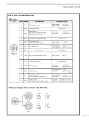
...180. 5 BAND Band voltage output. (Varies with amateur band) 6 ALC ALC voltage input. 7 NC 8 13.8 V 13.8 V output when power is ON. Goes to ground. 2 PANEL DESCRIPTION D ACC SOCKET INFORMATION • ACC socket ACC PIN # NAME DESCRIPTION 1 8V Regulated 8 V...than 20 mA orange yellow Output voltage : 0 to 8.0 V green Control voltage : -4 to 0 V Input impedance : More than 6.0 V/100 µA green • When connecting the ACC conversion cable (OPC-599) 13 9 10 11 12 5678 1234 2 4 5 1 3 8 6 7 ACC 1 2 4 5 1 3 6 7 ACC 2 ➀ FSKK ➁ GND ➂ SEND...
...180. 5 BAND Band voltage output. (Varies with amateur band) 6 ALC ALC voltage input. 7 NC 8 13.8 V 13.8 V output when power is ON. Goes to ground. 2 PANEL DESCRIPTION D ACC SOCKET INFORMATION • ACC socket ACC PIN # NAME DESCRIPTION 1 8V Regulated 8 V...than 20 mA orange yellow Output voltage : 0 to 8.0 V green Control voltage : -4 to 0 V Input impedance : More than 6.0 V/100 µA green • When connecting the ACC conversion cable (OPC-599) 13 9 10 11 12 5678 1234 2 4 5 1 3 8 6 7 ACC 1 2 4 5 1 3 6 7 ACC 2 ➀ FSKK ➁ GND ➂ SEND...
Instruction Manual
Page 11
...10 mm Soft solder 1-2 mm solder solder Strip the cable as possible. Soft solder the center conductor. Slide the connector body on p. 1 of this case, an antenna tuner is useful to match the transceiver and antenna. The IC-718 has an SWR meter to protect the final ... SWR continuously. 9 Low SWR allows full power for a specified frequency range and SWR may be a coaxial cable. The base of the transceiver has an adjustable stand for your operating conditions. When the SWR is of critical importance, along with the IC-718, see 'Supplied accessories' on and solder it...
...10 mm Soft solder 1-2 mm solder solder Strip the cable as possible. Soft solder the center conductor. Slide the connector body on p. 1 of this case, an antenna tuner is useful to match the transceiver and antenna. The IC-718 has an SWR meter to protect the final ... SWR continuously. 9 Low SWR allows full power for a specified frequency range and SWR may be a coaxial cable. The base of the transceiver has an adjustable stand for your operating conditions. When the SWR is of critical importance, along with the IC-718, see 'Supplied accessories' on and solder it...
Instruction Manual
Page 14
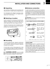
... optional PS-85 DC POWER SUPPLY when operating the IC-718 with AC power. Crimp 12 V battery Supplied DC power cable Solder Fuses NEVER connect to the diagrams below. DC power cable CONNECTING NON-ICOM DC POWER SUPPLY DC power supply AC outlet DC power 13.8 V 20 A socket _+ 13 9 10 11 12 5678 1234 AC cable _ black Supplied + red DC power cable 20 A fuses CONNECTING...
... optional PS-85 DC POWER SUPPLY when operating the IC-718 with AC power. Crimp 12 V battery Supplied DC power cable Solder Fuses NEVER connect to the diagrams below. DC power cable CONNECTING NON-ICOM DC POWER SUPPLY DC power supply AC outlet DC power 13.8 V 20 A socket _+ 13 9 10 11 12 5678 1234 AC cable _ black Supplied + red DC power cable 20 A fuses CONNECTING...
Instruction Manual
Page 16
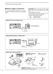
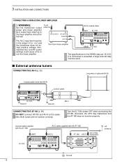
... and AH-4 at the same time. Turn the IC-718's power OFF when connecting the AT-180, otherwise, the CPU may malfunction and the AT-180 may not function properly. To an antenna RF OUTPUT RF INPUT SEND ALC Non-Icom linear amplifier 50 Ω coaxial cable ANT IC-718 SEND 13 9 10 11 12 5678 1234...
... and AH-4 at the same time. Turn the IC-718's power OFF when connecting the AT-180, otherwise, the CPU may malfunction and the AT-180 may not function properly. To an antenna RF OUTPUT RF INPUT SEND ALC Non-Icom linear amplifier 50 Ω coaxial cable ANT IC-718 SEND 13 9 10 11 12 5678 1234...
Instruction Manual
Page 32
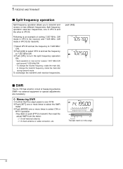
... operation is an example of measuring antenna SWR-no external equipment or special adjustments are necessary. ï Measuring SWR q Confirm that the output power is in VFO B (for receive) and 7.025 MHz, CW mode in this range. 30 Following is now set the frequency to change the transmit... frequency operation allows you to 7.057 MHz/CW. then read the actual SWR from the meter: ≤ 1.5 well matched antenna ≥ 1.5 check antenna or cable connection, etc. To exchange the transmit and receive frequencies, push [A/B]. s SWR The IC-718 has a built-in VFO B.
... operation is an example of measuring antenna SWR-no external equipment or special adjustments are necessary. ï Measuring SWR q Confirm that the output power is in VFO B (for receive) and 7.025 MHz, CW mode in this range. 30 Following is now set the frequency to change the transmit... frequency operation allows you to 7.057 MHz/CW. then read the actual SWR from the meter: ≤ 1.5 well matched antenna ≥ 1.5 check antenna or cable connection, etc. To exchange the transmit and receive frequencies, push [A/B]. s SWR The IC-718 has a built-in VFO B.

Instruction Manual
Page 50
... Remove the 5 screws from the sides, then lift up the top cover. s Optional bracket and carrying handle D Mounting bracket An optional IC-MB5 MOBILE MOUNTING BRACKET is available to install the radio under a table, on the transceiver. 9 INSTALLATION AND CONNECTIONS s Opening the transceiver's...there is approx. 3.80kg. Attach the MB-23 CARRYING HANDLE with the supplied rubber feet as shown. 48 CAUTION: DISCONNECT the DC power cable from the IC-718 before performing any work on a wall, in mind that the weight of the transceiver is danger of the transceiver, then remove the ...
... Remove the 5 screws from the sides, then lift up the top cover. s Optional bracket and carrying handle D Mounting bracket An optional IC-MB5 MOBILE MOUNTING BRACKET is available to install the radio under a table, on the transceiver. 9 INSTALLATION AND CONNECTIONS s Opening the transceiver's...there is approx. 3.80kg. Attach the MB-23 CARRYING HANDLE with the supplied rubber feet as shown. 48 CAUTION: DISCONNECT the DC power cable from the IC-718 before performing any work on a wall, in mind that the weight of the transceiver is danger of the transceiver, then remove the ...
Instruction Manual
Page 53
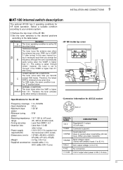
...⁄16(W) × 25⁄17(H) × 87⁄8(D) • Weight : 2.4 kg; 5 lb 4 oz • Supplied accessories : coaxial cable (1 m), ACC cable (DIN 13 pins) • Connector information for HF band operation. S2 NORMAL CONDITION D The tuner tunes when the SWR is ON (1 A max). 51 ...for the AT-180 • Frequency coverage : 1.9 - 54 MHz • Input impedance : 50 Ω • Maximum input : 120 W power • Minimum tuning : 8 W power • Matching impedance : 16.7-150 Ω (HF band) range 20 -125 Ω (50 MHz band) • Tuning accuracy : Less ...
...⁄16(W) × 25⁄17(H) × 87⁄8(D) • Weight : 2.4 kg; 5 lb 4 oz • Supplied accessories : coaxial cable (1 m), ACC cable (DIN 13 pins) • Connector information for HF band operation. S2 NORMAL CONDITION D The tuner tunes when the SWR is ON (1 A max). 51 ...for the AT-180 • Frequency coverage : 1.9 - 54 MHz • Input impedance : 50 Ω • Maximum input : 120 W power • Minimum tuning : 8 W power • Matching impedance : 16.7-150 Ω (HF band) range 20 -125 Ω (50 MHz band) • Tuning accuracy : Less ...
Instruction Manual
Page 54
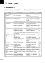
... possible with a spare one. (Fuses are not able to locate the cause of a problem or solve it to the threshold point. in the DC power cable and the internal PA unit.) p. 12 p. 53 No sound comes from the • Volume level is too low. • Rotate [AF] clockwise...memory channels have been programmed • Program different frequencies in the transmitting condition. • Check the SEND line of this chart, contact your nearest Icom Dealer or Service Center. Sensitivity is low. • The antenna is not connected properly. • The antenna for another station. • ...
... possible with a spare one. (Fuses are not able to locate the cause of a problem or solve it to the threshold point. in the DC power cable and the internal PA unit.) p. 12 p. 53 No sound comes from the • Volume level is too low. • Rotate [AF] clockwise...memory channels have been programmed • Program different frequencies in the transmitting condition. • Check the SEND line of this chart, contact your nearest Icom Dealer or Service Center. Sensitivity is low. • The antenna is not connected properly. • The antenna for another station. • ...
Instruction Manual
Page 55
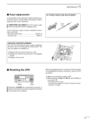
... all units in set mode to find the source of fuses installed for transceiver protection. • DC power cable fuses FGB 20 A • Circuitry fuse FGB 4 A DC POWER CABLE FUSE REPLACEMENT 20 A fuse CIRCUITRY FUSE REPLACEMENT The 13.8 V DC from the transceiver when changing a fuse. ...This fuse is applied to all programmed contents in memory channels and returns programmed values in the IC-718 through the circuitry fuse. CAUTION: DISCONNECT the DC power cable from the DC power cable is installed in the diagram at right. MAINTENANCE 10 s Fuse replacement If a fuse blows ...
... all units in set mode to find the source of fuses installed for transceiver protection. • DC power cable fuses FGB 20 A • Circuitry fuse FGB 4 A DC POWER CABLE FUSE REPLACEMENT 20 A fuse CIRCUITRY FUSE REPLACEMENT The 13.8 V DC from the transceiver when changing a fuse. ...This fuse is applied to all programmed contents in memory channels and returns programmed values in the IC-718 through the circuitry fuse. CAUTION: DISCONNECT the DC power cable from the DC power cable is installed in the diagram at right. MAINTENANCE 10 s Fuse replacement If a fuse blows ...
Instruction Manual
Page 57
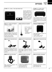
... cables for AT-180 specifications. HM-36 HAND MICROPHONE SP-20 EXTERNAL SPEAKER SP-21 EXTERNAL SPEAKER Hand microphone equipped with preset memories for each 100 kHz. can connect to use microphone. The PTT tuner start function provides simple operation. • Input power ...Input impedance: 8 Ω Max. 12 OPTIONS IC-PW1 HF + 50 MHz 1 KW LINER AMPLIFIER Full-duty 1 kW linear amplifier including an automatic antenna tuner. Same as supplied. 4 audio filters; Includes [UP]/[DOWN] switches and a low cut function. imput power: 5 W Designed for base station operation. ...
... cables for AT-180 specifications. HM-36 HAND MICROPHONE SP-20 EXTERNAL SPEAKER SP-21 EXTERNAL SPEAKER Hand microphone equipped with preset memories for each 100 kHz. can connect to use microphone. The PTT tuner start function provides simple operation. • Input power ...Input impedance: 8 Ω Max. 12 OPTIONS IC-PW1 HF + 50 MHz 1 KW LINER AMPLIFIER Full-duty 1 kW linear amplifier including an automatic antenna tuner. Same as supplied. 4 audio filters; Includes [UP]/[DOWN] switches and a low cut function. imput power: 5 W Designed for base station operation. ...


