
Instruction Manual
Page 2
... panel of the IC-718 which display the "CE" symbol on the transceiver rear panel. During maritime mobile operation, keep the transceiver and microphone as far away as a 24 V battery, to the transceiver if left there for the IC-718. BE CAREFUL! PRECAUTIONS R WARNING HIGH VOLTAGE! This could cause a fire or ruin the transceiver. Versions of the transceiver. IMPORTANT READ THIS INSTRUCTION MANUAL CAREFULLY before...
... panel of the IC-718 which display the "CE" symbol on the transceiver rear panel. During maritime mobile operation, keep the transceiver and microphone as far away as a 24 V battery, to the transceiver if left there for the IC-718. BE CAREFUL! PRECAUTIONS R WARNING HIGH VOLTAGE! This could cause a fire or ruin the transceiver. Versions of the transceiver. IMPORTANT READ THIS INSTRUCTION MANUAL CAREFULLY before...

Instruction Manual
Page 3
... panel 2 s Function display 5 s Rear panel 6 s Microphone (HM-36 8 3 INSTALLATION AND CONNECTIONS ......... 9 - 14 s Unpacking 9 s Selecting a location 9 s Grounding 9 s Antenna connection 9 s Required connections 10 s Advanced connections 11 s Power supply connections 12 s Liner amplifier connections 13 s External antenna tuners 14 4 FREQUENCY SETTING 15 - 19 s When first applying power 15 s Initial setting 15 s VFO description 16 s Frequency setting 17 s Dial lock function 19 5 RECEIVE AND TRANSMIT 20 - 34 s Mode selection 20 s Squelch and RF gain...
... panel 2 s Function display 5 s Rear panel 6 s Microphone (HM-36 8 3 INSTALLATION AND CONNECTIONS ......... 9 - 14 s Unpacking 9 s Selecting a location 9 s Grounding 9 s Antenna connection 9 s Required connections 10 s Advanced connections 11 s Power supply connections 12 s Liner amplifier connections 13 s External antenna tuners 14 4 FREQUENCY SETTING 15 - 19 s When first applying power 15 s Initial setting 15 s VFO description 16 s Frequency setting 17 s Dial lock function 19 5 RECEIVE AND TRANSMIT 20 - 34 s Mode selection 20 s Squelch and RF gain...
Instruction Manual
Page 4
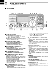
... GAIN/SQUELCH CONTROL [RF/SQL] (outer control; i LOCK SWITCH [LOCK] (p. 19) e HEADPHONE JACK [PHONES] (p. 11) Accepts headphones (8 Ω). • When headphones are connected, the internal speaker Push momentarily to turn power ON. Varies the audio output level from the speaker (closed con- 2 PANEL DESCRIPTION s Front panel Speaker Function Display @1 @0 !9 !8 !7 IC-718 MODE FIL TS 1 2 3 V/M A=B A/B 4 5 6 MW M -CL ˛ M V q PWR AF RF/SQL RIT SHIFT MIC PHONES w LOCK...
... GAIN/SQUELCH CONTROL [RF/SQL] (outer control; i LOCK SWITCH [LOCK] (p. 19) e HEADPHONE JACK [PHONES] (p. 11) Accepts headphones (8 Ω). • When headphones are connected, the internal speaker Push momentarily to turn power ON. Varies the audio output level from the speaker (closed con- 2 PANEL DESCRIPTION s Front panel Speaker Function Display @1 @0 !9 !8 !7 IC-718 MODE FIL TS 1 2 3 V/M A=B A/B 4 5 6 MW M -CL ˛ M V q PWR AF RF/SQL RIT SHIFT MIC PHONES w LOCK...
Instruction Manual
Page 5
... or turns the quick tuning step OFF. • While the quick tuning indicator (") is displayed, the frequency can be changed in 1 Hz steps. ➥ While the kHz quick tuning step is bypassed automatically after 20 sec. !5 SET SWITCH [SET] ➥ Push for 1 sec. Memory channel selection.(pgs. 4, 35) • [V/M], [A=B], [A/B], [MW], [M-CL], [M≈V], [SPL], [SCAN], [VOX], [NR] (option) and [ANF] (option) switch. (p. 4) !8 NOISE BLANKER SWITCH...
... or turns the quick tuning step OFF. • While the quick tuning indicator (") is displayed, the frequency can be changed in 1 Hz steps. ➥ While the kHz quick tuning step is bypassed automatically after 20 sec. !5 SET SWITCH [SET] ➥ Push for 1 sec. Memory channel selection.(pgs. 4, 35) • [V/M], [A=B], [A/B], [MW], [M-CL], [M≈V], [SPL], [SCAN], [VOX], [NR] (option) and [ANF] (option) switch. (p. 4) !8 NOISE BLANKER SWITCH...
Instruction Manual
Page 7
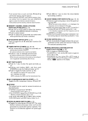
... S-meter while receiving. ➥ Functions as a Power, ALC or SWR meter while transmitting. (p. 26) !0 VFO/MEMORY INDICATOR (p. 16) "VFO A" or "B" appears when VFO mode is selected. !9 MODE INDICATORS (p. 20) Indicates the selected operating mode. 5 "MEMO" appears when memory mode is selected. !1 MEMORY CHANNEL NUMBER READOUT (p. 35) Shows the selected memory channel number. !2 BLANK INDICATOR (p. 38) Shows that the displayed memory channel is not programmed. •...
... S-meter while receiving. ➥ Functions as a Power, ALC or SWR meter while transmitting. (p. 26) !0 VFO/MEMORY INDICATOR (p. 16) "VFO A" or "B" appears when VFO mode is selected. !9 MODE INDICATORS (p. 20) Indicates the selected operating mode. 5 "MEMO" appears when memory mode is selected. !1 MEMORY CHANNEL NUMBER READOUT (p. 35) Shows the selected memory channel number. !2 BLANK INDICATOR (p. 38) Shows that the displayed memory channel is not programmed. •...
Instruction Manual
Page 10
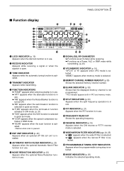
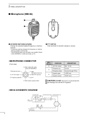
...) t PTT r Main readout squelch switch [MIC] PIN NO. 2 PANEL DESCRIPTION s Microphone (HM-36) q w q UP/DOWN SWITCHES [UP]/[DN] Change the selected readout frequency or memory channel. • Continuous pushing changes the frequency or memory channel number continuously. • The [UP]/[DN] switch can damage the internal 8 V regulator. • HM-36 SCHEMATIC DIAGRAM MICROPHONE MICROPHONE CABLE MICROPHONE PLUG MIC ELEMENT + 10µ 2k 4700p + 0.33µ 4700p DOWN UP qu wiy ert PTT RECEIVE 470 TRANSMIT 8
...) t PTT r Main readout squelch switch [MIC] PIN NO. 2 PANEL DESCRIPTION s Microphone (HM-36) q w q UP/DOWN SWITCHES [UP]/[DN] Change the selected readout frequency or memory channel. • Continuous pushing changes the frequency or memory channel number continuously. • The [UP]/[DN] switch can damage the internal 8 V regulator. • HM-36 SCHEMATIC DIAGRAM MICROPHONE MICROPHONE CABLE MICROPHONE PLUG MIC ELEMENT + 10µ 2k 4700p + 0.33µ 4700p DOWN UP qu wiy ert PTT RECEIVE 470 TRANSMIT 8
Instruction Manual
Page 11
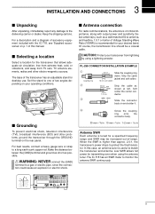
... coupling ring down. s Grounding To prevent electrical shock, television interference (TVI), broadcast interference (BCI) and other electro-magnetic sources. For a description and a diagram of accessory equipment included with output power and sensitivity. Slide the connector body on p. 1 of the transceiver has an adjustable stand for desktop use. 3 INSTALLATION AND CONNECTIONS s Unpacking After unpacking, immediately report any damage to monitor the antenna SWR continuously. 9
... coupling ring down. s Grounding To prevent electrical shock, television interference (TVI), broadcast interference (BCI) and other electro-magnetic sources. For a description and a diagram of accessory equipment included with output power and sensitivity. Slide the connector body on p. 1 of the transceiver has an adjustable stand for desktop use. 3 INSTALLATION AND CONNECTIONS s Unpacking After unpacking, immediately report any damage to monitor the antenna SWR continuously. 9
Instruction Manual
Page 12
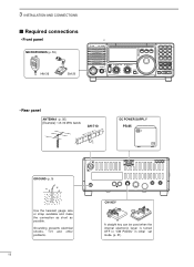
... turned OFF in "CW PADDL" in initial set mode. (p. 31) 3 INSTALLATION AND CONNECTIONS s Required connections • Front panel MICROPHONES (p. 55) HM-36 SM-20 IC-718 MODE FIL TS PWR AF RF/SQL RIT SHIFT MIC PHONES LOCK 1 2 3 V/M A=B A/B 4 5 6 MW M - CL ˛ M V 7 8 9 SPL SCN VOX . 0 NR ANF F-INP ENT NB COMP SET P.AMP ATT TUNER ∫ CH DN UP √ • Rear panel ANTENNA (p. 56) [Example]: 1.8-30 MHz bands...
... turned OFF in "CW PADDL" in initial set mode. (p. 31) 3 INSTALLATION AND CONNECTIONS s Required connections • Front panel MICROPHONES (p. 55) HM-36 SM-20 IC-718 MODE FIL TS PWR AF RF/SQL RIT SHIFT MIC PHONES LOCK 1 2 3 V/M A=B A/B 4 5 6 MW M - CL ˛ M V 7 8 9 SPL SCN VOX . 0 NR ANF F-INP ENT NB COMP SET P.AMP ATT TUNER ∫ CH DN UP √ • Rear panel ANTENNA (p. 56) [Example]: 1.8-30 MHz bands...
Instruction Manual
Page 18
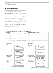
... channel 1 is selected. Memory mode is selected again. Changed frequency (14.123 MHz) does not appear and memorized frequency (14.100 MHz) appears instead. 16 4 FREQUENCY SETTING s VFO description VFO is an abbreviation of Variable Frequency Oscillator, and traditionally refers to the VFO with the band stacking register (p. 18). You can call up a desired frequency to an oscillator. Changed frequency (14.123 MHz) appears. The IC-718...
... channel 1 is selected. Memory mode is selected again. Changed frequency (14.123 MHz) does not appear and memorized frequency (14.100 MHz) appears instead. 16 4 FREQUENCY SETTING s VFO description VFO is an abbreviation of Variable Frequency Oscillator, and traditionally refers to the VFO with the band stacking register (p. 18). You can call up a desired frequency to an oscillator. Changed frequency (14.123 MHz) appears. The IC-718...
Instruction Manual
Page 19
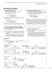
...] one or more times to enter the frequency dig- When the displayed frequency exits the transmit frequency range (ham band), a band edge beep may be skipped. e Push the numeral keys to select the general coverage receiver band. e Rotate the tuning dial to select the desired ham band. • For general coverage receiver use The IC-718 has a general coverage receiver band. D Direct frequency entry with the mode switch. (p. 20). 4 FREQUENCY SETTING s Frequency setting D Using the tuning dial q Push...
...] one or more times to enter the frequency dig- When the displayed frequency exits the transmit frequency range (ham band), a band edge beep may be skipped. e Push the numeral keys to select the general coverage receiver band. e Rotate the tuning dial to select the desired ham band. • For general coverage receiver use The IC-718 has a general coverage receiver band. D Direct frequency entry with the mode switch. (p. 20). 4 FREQUENCY SETTING s Frequency setting D Using the tuning dial q Push...
Instruction Manual
Page 29
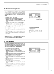
...; VOX operation The VOX (Voice-operated Transmission) function toggles between transmit and receive with your computer, etc. w Select "VOX Gain" in the range of the ALC zone. • Be sure the mic gain is transmitting. 5 RECEIVE AND TRANSMIT ˛ ˛ ï Microphone compressor IC-718 has a built-in quick set mode. • Push [∫ UP]/[√ DN] one or more times to select "VOX Delay" t While speaking into the microphone, adjust [VOX...
...; VOX operation The VOX (Voice-operated Transmission) function toggles between transmit and receive with your computer, etc. w Select "VOX Gain" in the range of the ALC zone. • Be sure the mic gain is transmitting. 5 RECEIVE AND TRANSMIT ˛ ˛ ï Microphone compressor IC-718 has a built-in quick set mode. • Push [∫ UP]/[√ DN] one or more times to select "VOX Delay" t While speaking into the microphone, adjust [VOX...
Instruction Manual
Page 31
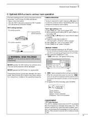
... and holding [SET], push [PWR] to turn power ON again. • MANUAL TUNING q Set the desired frequency in initial set mode (p. 46). 29 w Push and hold [TUNER]" operation and activates first transmission on the transceiver directly. Transmitting before transmitting when you change the frequency-even slightly. Note that the AH-4 cannot tune when using a 1⁄2 λ long wire or multiple of the ham bands, the AH...
... and holding [SET], push [PWR] to turn power ON again. • MANUAL TUNING q Set the desired frequency in initial set mode (p. 46). 29 w Push and hold [TUNER]" operation and activates first transmission on the transceiver directly. Transmitting before transmitting when you change the frequency-even slightly. Note that the AH-4 cannot tune when using a 1⁄2 λ long wire or multiple of the ham bands, the AH...
Instruction Manual
Page 32
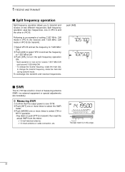
To exchange the transmit and receive frequencies, push [A/B]. s SWR The IC-718 has a built-in this range. 30 Following is an example of measuring antenna SWR-no external equipment or special adjustments are necessary. ï Measuring SWR q Confirm that the output power is over 30 W. q Select VFO B and set the frequency to 7.057 MHz/CW. Split frequency operation uses two frequencies, one or more times to transmit; w Push...
To exchange the transmit and receive frequencies, push [A/B]. s SWR The IC-718 has a built-in this range. 30 Following is an example of measuring antenna SWR-no external equipment or special adjustments are necessary. ï Measuring SWR q Confirm that the output power is over 30 W. q Select VFO B and set the frequency to 7.057 MHz/CW. Split frequency operation uses two frequencies, one or more times to transmit; w Push...
Instruction Manual
Page 33
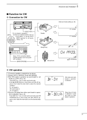
... delay time when semi break-in operation is selected. (See p. 43) • Push [SET] for 1 sec. w Select CW (or CW-REV) mode with [MODE]. or use the RTTY 13 9 10 11 12 5678 SEND terminal for all bands. (See p. 33) 1234 ˛ ˛ See p. 32 for connection details: Paddle operation from front panel MIC connector. [MICROPHONE] 5 RECEIVE AND TRANSMIT Paddle Straight key Initial set mode...
... delay time when semi break-in operation is selected. (See p. 43) • Push [SET] for 1 sec. w Select CW (or CW-REV) mode with [MODE]. or use the RTTY 13 9 10 11 12 5678 SEND terminal for all bands. (See p. 33) 1234 ˛ ˛ See p. 32 for connection details: Paddle operation from front panel MIC connector. [MICROPHONE] 5 RECEIVE AND TRANSMIT Paddle Straight key Initial set mode...
Instruction Manual
Page 34
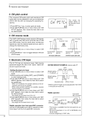
... CW mode. MODE 1/2 octave BFO Desired signal Interference (600 Hz) (800 Hz) CW mode (USB side) Desired signal Interference (600 Hz) (400 Hz) CW REV mode (LSB side) KEYING WEIGHT EXAMPLE: morse code "K" Weight setting: 1:1:3 (default) DOT DASH (Fixed*) DASH Weight setting: Adjusted Adjustable range SPACE (Fixed*) *SPACE and DOT length can be adjusted with out changing the operating frequency. e Push [∫ UP]/[√ DN] one or more times until...
... CW mode. MODE 1/2 octave BFO Desired signal Interference (600 Hz) (800 Hz) CW mode (USB side) Desired signal Interference (600 Hz) (400 Hz) CW REV mode (LSB side) KEYING WEIGHT EXAMPLE: morse code "K" Weight setting: 1:1:3 (default) DOT DASH (Fixed*) DASH Weight setting: Adjusted Adjustable range SPACE (Fixed*) *SPACE and DOT length can be adjusted with out changing the operating frequency. e Push [∫ UP]/[√ DN] one or more times until...
Instruction Manual
Page 36
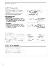
... used on the HF bands. RTTY sift frequency is reversed between MARK and SPACE. t Operate the connected PC or TNC (TU). to enter quick set to select RTTY-R (RTTY reverse) mode. e Select the desired FSK tone/shift frequencies and keying polarity the same way as below. Reverse space mark 2125 170 Hz Hz BFO displayed freq. 34 5 RECEIVE AND TRANSMIT ï RTTY (FSK) operation q Connect a terminal unit...
... used on the HF bands. RTTY sift frequency is reversed between MARK and SPACE. t Operate the connected PC or TNC (TU). to enter quick set to select RTTY-R (RTTY reverse) mode. e Select the desired FSK tone/shift frequencies and keying polarity the same way as below. Reverse space mark 2125 170 Hz Hz BFO displayed freq. 34 5 RECEIVE AND TRANSMIT ï RTTY (FSK) operation q Connect a terminal unit...
Instruction Manual
Page 41
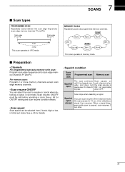
... low, in Initial set mode, the scan pauses for details. • Squelch condition Scan start with Programmed scan Memory scan Squelch open closed If you set scan resume ON in Initial set before operating a scan. See p. 45 for 10 sec. Scan pauses on each channel when the scan resume is paused, scan resumes 2 sec. s Preparation • Channels For programmed scan/auto memory write scan: Program scan edge frequencies into scan edge memory channels P1 and P2. MEMORY SCAN Repeatedly scans all programmed...
... low, in Initial set mode, the scan pauses for details. • Squelch condition Scan start with Programmed scan Memory scan Squelch open closed If you set scan resume ON in Initial set before operating a scan. See p. 45 for 10 sec. Scan pauses on each channel when the scan resume is paused, scan resumes 2 sec. s Preparation • Channels For programmed scan/auto memory write scan: Program scan edge frequencies into scan edge memory channels P1 and P2. MEMORY SCAN Repeatedly scans all programmed...
Instruction Manual
Page 46
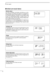
... and only plan on using LSB and USB modes, use "MODE SELECTION" to inhibit access to set on or off , push [MODE] one or more times until the desired mode is displayed. The default is on . • Beep level This item adjusts the confirmation beep level. The default is 50. • Band edge beep A beep sounds when an operating frequency enters or exits a transmit frequency range. The default is on or off...
... and only plan on using LSB and USB modes, use "MODE SELECTION" to inhibit access to set on or off , push [MODE] one or more times until the desired mode is displayed. The default is on . • Beep level This item adjusts the confirmation beep level. The default is 50. • Band edge beep A beep sounds when an operating frequency enters or exits a transmit frequency range. The default is on or off...
Instruction Manual
Page 47
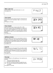
... Low can be used when listening to 50 KHz/revolution in 50 Hz tuning step during scan operations. The default is available on AM mode. When auto tuning step is turned on . • AM Noise blanker When this increases to regular AM broadcasts as it may degrade the receive audio). Four selections are scanned during quick rotation of the paddle. after stopping...
... Low can be used when listening to 50 KHz/revolution in 50 Hz tuning step during scan operations. The default is available on AM mode. When auto tuning step is turned on . • AM Noise blanker When this increases to regular AM broadcasts as it may degrade the receive audio). Four selections are scanned during quick rotation of the paddle. after stopping...
Instruction Manual
Page 54
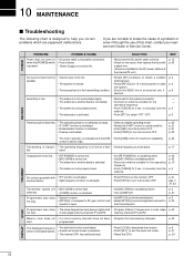
... chart is blown. when the [POWER] switch • Fuse is designed to help you are • [MIC GAIN] is open p. 2 the squelch. • The transceiver is not properly tuned. • Set [RF POWER] to a suitable position. • Set [MIC GAIN] to the antenna connector. • Connect an antenna suitable for the operating frequency. • Push [TUNER] for 2 sec. band. start . If you correct problems which are installed in the transmitting...
... chart is blown. when the [POWER] switch • Fuse is designed to help you are • [MIC GAIN] is open p. 2 the squelch. • The transceiver is not properly tuned. • Set [RF POWER] to a suitable position. • Set [MIC GAIN] to the antenna connector. • Connect an antenna suitable for the operating frequency. • Push [TUNER] for 2 sec. band. start . If you correct problems which are installed in the transmitting...


