

Instruction Manual
Page 3
...1 TABLE OF CONTENTS 1 SUPPLIED ACCESSORIES 1 2 PANEL DESCRIPTION 2 - 8 s Front panel 2 s Function display 5 s Rear panel 6 s Microphone (HM-36 8 3 INSTALLATION AND CONNECTIONS ......... 9 - 14 s Unpacking 9 s Selecting a location 9 s Grounding 9 s Antenna connection 9 s Required connections 10 s Advanced connections 11 s Power supply connections...Mode selection 20 s Squelch and RF gain 20 s Function for receive 21 s DSP function (option 23 s Filter selection 24 s Filter setting 25 s Function for transmit 26 s Split frequency operation 30 s SWR 30 s Function for CW 31 s ...
...1 TABLE OF CONTENTS 1 SUPPLIED ACCESSORIES 1 2 PANEL DESCRIPTION 2 - 8 s Front panel 2 s Function display 5 s Rear panel 6 s Microphone (HM-36 8 3 INSTALLATION AND CONNECTIONS ......... 9 - 14 s Unpacking 9 s Selecting a location 9 s Grounding 9 s Antenna connection 9 s Required connections 10 s Advanced connections 11 s Power supply connections...Mode selection 20 s Squelch and RF gain 20 s Function for receive 21 s DSP function (option 23 s Filter selection 24 s Filter setting 25 s Function for transmit 26 s Split frequency operation 30 s SWR 30 s Function for CW 31 s ...
Instruction Manual
Page 7
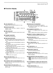
...operating frequency. !6 REVERSE INDICATOR (p.19) Appears when the CW reverse or RTTY reverse mode is selected. !7 WIDE/NARROW FILTER INDICATORS (pgs. 24, 25) ➥" " appears when the wide IF filter is selected. ➥" " appears when the narrow IF... programmable tuning step is selected. !9 MODE INDICATORS (p. 20) Indicates the selected operating mode. 5 u AUTOMATIC NOTCH FILTER INDICATOR (p. 23) Appears when the optional Automatic Notch Filter function is installed. r TRANSMIT INDICATOR Appears while transmitting. y DSP UNIT INDICATOR (p. 49) Appears when an optional UT-106 DSP ...
...operating frequency. !6 REVERSE INDICATOR (p.19) Appears when the CW reverse or RTTY reverse mode is selected. !7 WIDE/NARROW FILTER INDICATORS (pgs. 24, 25) ➥" " appears when the wide IF filter is selected. ➥" " appears when the narrow IF... programmable tuning step is selected. !9 MODE INDICATORS (p. 20) Indicates the selected operating mode. 5 u AUTOMATIC NOTCH FILTER INDICATOR (p. 23) Appears when the optional Automatic Notch Filter function is installed. r TRANSMIT INDICATOR Appears while transmitting. y DSP UNIT INDICATOR (p. 49) Appears when an optional UT-106 DSP ...
Instruction Manual
Page 25
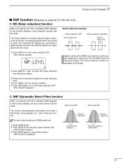
... [NR] again to exit the setting condition. to turn the noise reduction OFF. • [NR] indicator disappears. ï ANF (Automatic Notch Filter) function When an optional UT-106 is installed (DSP appears in the function display), an auto notch function can be used . w Push [ANF] to enter the noise reduction level setting... for 1 sec. 5 RECEIVE AND TRANSMIT s DSP function (Requires an optional UT-106 DSP UNIT) ï NR (Noise reduction) function When an optional UT-106 is installed (DSP appears in the function display), noise reduction function can be used .
... [NR] again to exit the setting condition. to turn the noise reduction OFF. • [NR] indicator disappears. ï ANF (Automatic Notch Filter) function When an optional UT-106 is installed (DSP appears in the function display), an auto notch function can be used . w Push [ANF] to enter the noise reduction level setting... for 1 sec. 5 RECEIVE AND TRANSMIT s DSP function (Requires an optional UT-106 DSP UNIT) ï NR (Noise reduction) function When an optional UT-106 is installed (DSP appears in the function display), noise reduction function can be used .
Instruction Manual
Page 26
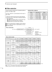
An optional filter is installed, set the optional filter in initial set mode. (see right) FL-96 6 K* 2.8 K 2.4 K 6 K* 2.8 K 2.4 K 6 K* 2.8 K 2.4 K 6 K 2.4 K 2.8 K* FL-222 6 K* 2.4 K 1.8 K 6 K* 2.4 K 1.8 K 6 K* 2.4 K 1.8 K FL-257 6 K* 3.3 K 2.4 K 6 K* 3.3 K 2.4 K 6 K* 3.3 K... times to select the desired filter combination. • ã or ç does not appear while in each mode. Narrow, SSB/CW/RTTY; Wide • Filter selection table no FL-52A FL-53A WIDE 6 K* 6 K* 6 K* SSB NORMAL 2.4 K 2.4 K 2.4 K NARROW 500* 250* WIDE 6 K* 6 K* 6 K* CW ...
An optional filter is installed, set the optional filter in initial set mode. (see right) FL-96 6 K* 2.8 K 2.4 K 6 K* 2.8 K 2.4 K 6 K* 2.8 K 2.4 K 6 K 2.4 K 2.8 K* FL-222 6 K* 2.4 K 1.8 K 6 K* 2.4 K 1.8 K 6 K* 2.4 K 1.8 K FL-257 6 K* 3.3 K 2.4 K 6 K* 3.3 K 2.4 K 6 K* 3.3 K... times to select the desired filter combination. • ã or ç does not appear while in each mode. Narrow, SSB/CW/RTTY; Wide • Filter selection table no FL-52A FL-53A WIDE 6 K* 6 K* 6 K* SSB NORMAL 2.4 K 2.4 K 2.4 K NARROW 500* 250* WIDE 6 K* 6 K* 6 K* CW ...
Instruction Manual
Page 27
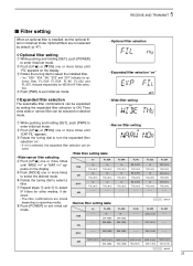
... NOR (2.4 K) NOR (2.4 K) NOR (2.4 K) NOR (2.4 K) AM 52A (500) 53A (250) 96 (2.8 K) 222 (1.8 K) 257 (3.3 K) : default 25 i Push [POWER] to select IF filters for 455 kHz IF filter selection. no 52A (500) FL-53A no THU (6 K) no THU (6 K) no THU (6 K) - - - FL-53A no FL-52A SSB - - - ... expanded by default. (p. 47) • Optional filter selection D Optional filter setting q While pushing and holding [SET], push [PWR] to select the installed filter. • "no," "52A," "53A," "96," "222" and "257" indicate no THU (6 K) - - - FL-52A no THU (6 ...
... NOR (2.4 K) NOR (2.4 K) NOR (2.4 K) NOR (2.4 K) AM 52A (500) 53A (250) 96 (2.8 K) 222 (1.8 K) 257 (3.3 K) : default 25 i Push [POWER] to select IF filters for 455 kHz IF filter selection. no 52A (500) FL-53A no THU (6 K) no THU (6 K) no THU (6 K) - - - FL-53A no FL-52A SSB - - - ... expanded by default. (p. 47) • Optional filter selection D Optional filter setting q While pushing and holding [SET], push [PWR] to select the installed filter. • "no," "52A," "53A," "96," "222" and "257" indicate no THU (6 K) - - - FL-52A no THU (6 ...
Instruction Manual
Page 49
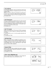
... in the range 01H to 7FH. The default is installed, this selection expands filter and filter selection (W/N) key combination on . • CI-V 731 mode When connecting the IC-718 to other Icom HF transceivers or receivers. The default is oF (off ). • OPTION Filter When an optional IF filer is on operating...
... in the range 01H to 7FH. The default is installed, this selection expands filter and filter selection (W/N) key combination on . • CI-V 731 mode When connecting the IC-718 to other Icom HF transceivers or receivers. The default is oF (off ). • OPTION Filter When an optional IF filer is on operating...
Instruction Manual
Page 52
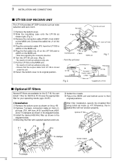
...unit. r Mounting the filter with UT-106 s Optional IF filters Several IF filters are available for the IC-718. Connect the cable into J3 on the UT-106 and to fix with an adhesive strip, etc. y Turn the UT-106... P 1 W 4 t Solder the 4 leads. After filter installation, specify the installed filter using initial set mode. (p. 47) Otherwise, the installed filter will not function properly. Optional IF filter J 1 W 5 J 701 J 4101 MAIN unit Tr-clamper Solder 4 leads Tr-clamper 50 e Install the desired 455 KHz filter as shown in the diagram...
...unit. r Mounting the filter with UT-106 s Optional IF filters Several IF filters are available for the IC-718. Connect the cable into J3 on the UT-106 and to fix with an adhesive strip, etc. y Turn the UT-106... P 1 W 4 t Solder the 4 leads. After filter installation, specify the installed filter using initial set mode. (p. 47) Otherwise, the installed filter will not function properly. Optional IF filter J 1 W 5 J 701 J 4101 MAIN unit Tr-clamper Solder 4 leads Tr-clamper 50 e Install the desired 455 KHz filter as shown in the diagram...

