
Icom IC-718 Support Question
Icom IC-718 Support Question
Find answers below for this question about Icom IC-718.Need a Icom IC-718 manual? We have 1 online manual for this item!
Question posted by py6hz on September 28th, 2021
Radio Icom Ic 718
my dsp ic 718 and ATT not working
Current Answers
Answer #1: Posted by SonuKumar on September 28th, 2021 9:32 AM
SonuKumar

Member since:
May 9th, 2021 Points: 16,598,000

Member since:
May 9th, 2021 Points: 16,598,000
http://www.icomcanada.com/pdf_manual/amateur/ic-718.pdf
follow page 52 onwards
Please respond to my effort to provide you with the best possible solution by using the "Acceptable Solution" and/or the "Helpful" buttons when the answer has proven to be helpful.
Regards,
Sonu
Your search handyman for all e-support needs!!
Related Icom IC-718 Manual Pages
Instruction Manual - Page 2
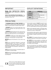
...ignition voltage spikes. Use Icom microphones only (supplied or optional).
BE CAREFUL! This
manual contains important safety and operating instructions for Commercially Available Amateur Radio Equipment). R NEVER let ... if left there for long periods.
NEVER expose the transceiver to the IC-718 may result in direct sunlight. AVOID placing the transceiver against walls or putting...
Instruction Manual - Page 4
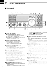
2 PANEL DESCRIPTION
s Front panel
Speaker Function Display
@1 @0 !9 !8
!7
IC-718
MODE FIL
TS
1 2 3 V/M
A=B
A/B
4 5 6 MW
M -CL
˛
M V
q
PWR AF RF/SQL RIT SHIFT
MIC
PHONES
w
LOCK
7 8 9 SPL
SCN
VOX
. 0 NR
ANF
F-INP ENT
!6
NB COMP SET
!5
P.AMP ATT TUNER
!4
!3
CH √ DN UP ∫
!2
e
rt
yu i
o
!0 !1
or rotate the control counterclockwise to decrease the...
Instruction Manual - Page 11
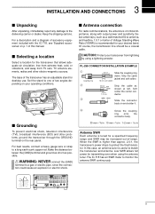
..., TV antenna elements, radios and other problems, ground the transceiver through the GROUND terminal on p. 1 of accessory equipment included with output power and sensitivity.
The IC-718 has an SWR meter ...
Strip the cable as possible.
When the SWR is of critical importance, along with the IC-718, see 'Supplied accessories' on the rear panel. Low SWR allows full power for your ...
Instruction Manual - Page 12
...CL
˛
M V
7 8 9 SPL
SCN
VOX
. 0 NR
ANF
F-INP ENT
NB COMP SET P.AMP ATT TUNER
∫
CH
DN UP √
• Rear panel
ANTENNA (p. 56) [Example]: 1.8-30 MHz bands
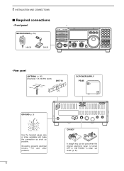
... 31) 3 INSTALLATION AND CONNECTIONS
s Required connections
• Front panel
MICROPHONES (p. 55)
HM-36
SM-20
IC-718
MODE FIL
TS
PWR AF RF/SQL RIT SHIFT MIC
PHONES LOCK
1 2 3 V/M
A=B
A/B
4 5 6 MW
M -
Instruction Manual - Page 13
...∫
M V
7 8 9 SPL
SCN
VOX
. 0 NR
ANF
F-INP ENT
NB COMP SET P.AMP ATT TUNER
∫
CH
DN UP ∫
HEADPHONES
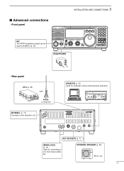
• Rear panel
AH-4 (p. 55) with
AH-2b or...57) Used for connecting a non-Icom linear amplifier. 3 INSTALLATION AND CONNECTIONS
s Advanced connections
• Front panel
MIC The AFSK modulation signal can be input from [MIC]. (p. 33)
IC-718
MODE FIL
TS
PWR AF RF/...
Instruction Manual - Page 14
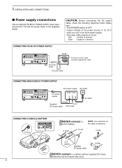
...The [POWER] switch is OFF.
• Output voltage of the power source is 12-15 V
when you use a non-Icom power supply.
• DC power cable polarity is correct. Red
: positive + terminal
Black : negative _ terminal
PS-85...Use an optional PS-85 DC POWER SUPPLY when operating the IC-718 with AC power. Refer to
a 24 V battery.
_ black
+ red
NOTE: Use terminals for the cable connections.
Instruction Manual - Page 15
...-European versions : 100-120/220-240 V
European version
: 230 V)
GND Ground
ACC REMOTE
13 9 10 11 12 5678 1234
IC-718
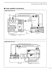
CONNECTING THE IC-4KL
Coaxial cable (supplied with the IC-4KL)
ACC cable (supplied with the IC-4KL)
OPC599 conversion cable (option)
To an antenna
ACC
ANT ACC
13 9 10 11 12 5678 1234...
Instruction Manual - Page 16
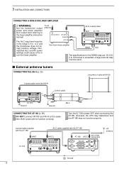
...THE AH-4 (p. 29)
Long wire or optional AH-2b
Coaxial cable (from the AH-4)
Control cable
IC-718 Ground
Ground
AH-4
CONNECTING THE AT-180 (p. 28)
DO NOT! Nonmatched ALC and RF power settings could...linear amplifier. To an antenna
RF OUTPUT RF INPUT SEND ALC
Non-Icom linear amplifier
50 Ω coaxial cable ANT IC-718
SEND
13 9 10 11 12 5678 1234
ALC
The specifications for ...
Instruction Manual - Page 18
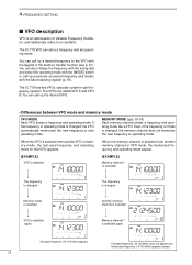
The IC-718 VFO can call up the desired VFO.
• Differences between VFO mode and memory mode
VFO MODE Each ... and modes with the keypad or the memory transfer function (see p. 37). You can store a frequency and an operating mode.
The IC-718 has two VFOs, specially suited for that VFO appears. Changed frequency (14.123 MHz) appears. If the frequency or operating mode is...
Instruction Manual - Page 19
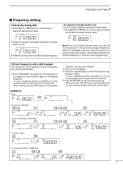
... tuning dial
q Push [∫ UP] or [√ DN] one or more times to select the desired ham band.
• For general coverage receiver use The IC-718 has a general coverage receiver band.
w Push [•] on initial set the transceiver to the general coverage frequency. e Push the numeral keys to select
the general...
Instruction Manual - Page 20
...;
General (old)
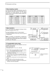
Programmable tuning step indicator 10 KHz tuning steps is selected.
18
General (new)
D Programmable tuning steps
Programmable tuning steps are included in the IC-718.
t Rotate the tuning dial to select the desired band. • Pushing [∫ UP]/[√ DN] continuously scrolls through the available bands. BAND 1.9 MHz 3.5 MHz 7 MHz...
Instruction Manual - Page 22
... the S-meter to the max.
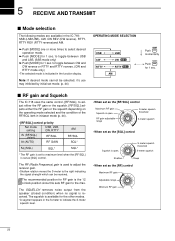
5 RECEIVE AND TRANSMIT
s Mode selection
The following modes are available in the IC-718: SSB (LSB/USB), CW, CW REV (CW reverse), RTTY, RTTY REV (RTTY reverse)and AM.
&#...more times to maximum level when the [RF/SQL] is set as [SQL] control. The RF (Radio Frequency) gain is the 12 o'clock position since this sets RF gain to the right indicating the signal...
Instruction Manual - Page 29
... the ALC zone. This function provides an opportunity to 50.
i Push [SET] to turn the function ON. 5 RECEIVE AND TRANSMIT
˛ ˛
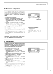
ï Microphone compressor
IC-718 has a built-in quick set mode.
• Push [SET] for 1 sec. This circuit increases your voice.
Instruction Manual - Page 31
... indicator; 5 RECEIVE AND TRANSMIT
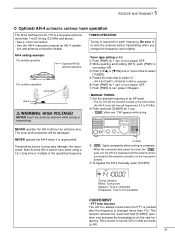
ï Optional AH-4 AUTOMATIC ANTENNA TUNER operation
The AH-4 matches the IC-718 to a long wire antenna more times to select
[TUNER]. Be sure to the antenna connector on the...B2 A/B3 MW4 M=C5L M V6 SP7L SCN8 VOX9 .NR ANF0 FE-INNPT
NB COMP SET P.AMP ATT TUNER
CH
DN UP∫
R WARNING: HIGH VOLTAGE! Blinks: Tuning now Appears: Tune is completed ...
Instruction Manual - Page 32
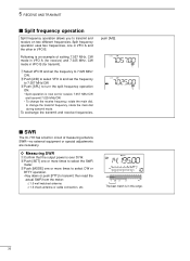
... the output power is in circuit of setting 7.057 MHz, CW mode in VFO A (for receive) and 7.025 MHz, CW mode in VFO B. s SWR
The IC-718 has a built-in this range.
30 The best match is over 30 W. w Push [SET] one or more times to select CW or
RTTY operation. •...
Instruction Manual - Page 34
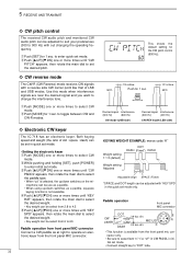
... default setting for 1 sec. q Push [SET] for the CW pitch control (600 Hz).
to toggle between CW and CW-R modes.
ï Electronic CW keyer
The IC-718 has an electronic keyer. w Push [∫ UP]/[√ DN] one or more times until "KEY
RAT" appears, then rotate the main dial to select the...
Instruction Manual - Page 43
... [SET] momentarily.
[DIAL]
[SET]
√
[√] [∫]
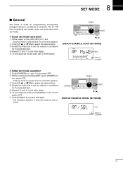
[DISPLAY EXAMPLE: QUICK SET MODE]
Item Value of its items appears. r Repeat w and e to
turn power OFF.
The IC-718 has 2 separate set modes: quick set mode and initial set mode operation
q Push [POWER] for 1 sec.
Instruction Manual - Page 49
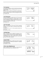
...IC-718 connected to 7FH. See p. 24 for usable filters for each CI-V transceiver has its own Icom standard address in the range 01H to other Icom HF transceivers or receivers. When 2 or more IC-718s...When an optional IF filter is selected, changing the frequency, operating mode, etc. The IC-718's address is necessary, otherwise the filters cannot be set to 4 bytes. •...
Instruction Manual - Page 50
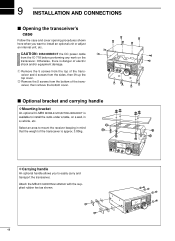
...lift up the top cover. s Optional bracket and carrying handle
D Mounting bracket
An optional IC-MB5 MOBILE MOUNTING BRACKET is available to mount the receiver keeping in a vehicle, etc. ...radio under a table, on the transceiver.
Attach the MB-23 CARRYING HANDLE with the supplied rubber feet as shown.
48 CAUTION: DISCONNECT the DC power cable
from the IC-718 before performing any work...
Instruction Manual - Page 59
...
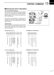
The CI-V system can be connected to 4 Icom CI-V transceivers or receivers can be connected through an optional CT-17 CI-V LEVEL CONVERTER to command numbers. IC-718
˛
˛
BC-25 (optional) 9-15...fixed)
Controller's default address Transceiver's default address
OK code (fixed) End of message code (fixed)
IC-718 TO CONTROLLER
q wert
y
u
FE FE E0 5E Cn Sc Data area FD
NG MESSAGE TO...
Similar Questions

How Can I Open The Ic 7200 For Transmission On Marine Channels?
I have been adviced that it is possible to modify so that I for safety reasons only, can trx on mari...
I have been adviced that it is possible to modify so that I for safety reasons only, can trx on mari...
(Posted by Runeedamm 5 months ago)

Trying To Id Parts
can anyone ID the burned components just to the right of the fuse.
can anyone ID the burned components just to the right of the fuse.
(Posted by Sc403 1 year ago)


Icom Ic-718 Switches Frequencies When Keying In Cw Mode
I was attempting to tune my 12 meter antenna and was using the built-in SWR meter. I set the frequen...
I was attempting to tune my 12 meter antenna and was using the built-in SWR meter. I set the frequen...
(Posted by ddennisberger 8 years ago)