

Instruction Manual
Page 3
...- 40 s Scan types 39 s Preparation 39 s Programmed scan operation 40 s Memory scan operation 40 8 SET MODE 41 - 47 s General 41 s Quick set mode items 42-43 s Initial set mode items 44-47 9 INSTALLATION AND CONNECTIONS ....... 48 - 51 s Opening the transceiver's case 48 s Optional bracket and...applying power 15 s Initial setting 15 s VFO description 16 s Frequency setting 17 s Dial lock function 19 5 RECEIVE AND TRANSMIT 20 - 34 s Mode selection 20 s Squelch and RF gain 20 s Function for receive 21 s DSP function (option 23 s Filter selection 24 s Filter setting 25 s ...
...- 40 s Scan types 39 s Preparation 39 s Programmed scan operation 40 s Memory scan operation 40 8 SET MODE 41 - 47 s General 41 s Quick set mode items 42-43 s Initial set mode items 44-47 9 INSTALLATION AND CONNECTIONS ....... 48 - 51 s Opening the transceiver's case 48 s Optional bracket and...applying power 15 s Initial setting 15 s VFO description 16 s Frequency setting 17 s Dial lock function 19 5 RECEIVE AND TRANSMIT 20 - 34 s Mode selection 20 s Squelch and RF gain 20 s Function for receive 21 s DSP function (option 23 s Filter selection 24 s Filter setting 25 s ...
Instruction Manual
Page 6
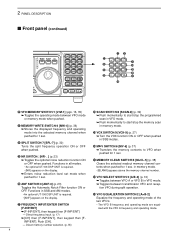
.... 16, 35) ➥ Toggles the operating mode between transmission VFO and reception VFO during split operation. #3 VFO EQUALIZATION SWITCH/2 [A=B•2] Equalize the frequency and operating mode of the two VFO's. • The VFO B frequency and operating mode are equalized with the VFO A frequency and operating mode. 4 Functions in SSB modes. #0 M≈V SWITCH/6 [MV•6] (p. 37) ➥...
.... 16, 35) ➥ Toggles the operating mode between transmission VFO and reception VFO during split operation. #3 VFO EQUALIZATION SWITCH/2 [A=B•2] Equalize the frequency and operating mode of the two VFO's. • The VFO B frequency and operating mode are equalized with the VFO A frequency and operating mode. 4 Functions in SSB modes. #0 M≈V SWITCH/6 [MV•6] (p. 37) ➥...
Instruction Manual
Page 7
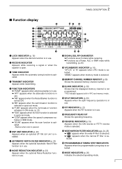
... channel number. !2 BLANK INDICATOR (p. 38) Shows that the displayed memory channel is not programmed. • This indicator appears both in VFO and memory mode. !3 SPLIT INDICATORS (p. 30) Appears when the split frequency operation is in use. !4 RIT INDICATOR (p. 21) Appears when the RIT function is in use . !5 FREQUENCY READOUT Shows the operating frequency...
... channel number. !2 BLANK INDICATOR (p. 38) Shows that the displayed memory channel is not programmed. • This indicator appears both in VFO and memory mode. !3 SPLIT INDICATORS (p. 30) Appears when the split frequency operation is in use. !4 RIT INDICATOR (p. 21) Appears when the RIT function is in use . !5 FREQUENCY READOUT Shows the operating frequency...
Instruction Manual
Page 17
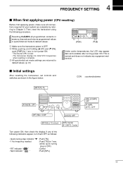
...]: 12 o'clock [RIT]: Center [IF SHIFT]: Center Turn power ON, then check the display. s Initial settings After resetting the transceiver, set mode to default values. (p. 41) [PWR] √ [√] [∫] Under cooler temperatures, the LCD may appear dark and unstable after turning ...internal CPU is reset. • The transceiver displays its initial VFO frequencies when resetting is OFF) • RIT indicator " RIT " : Center. • Split indicator " " : Push [SPL]. [NB], [COMP]: OFF [P.AMP], [ATT],: OFF 15 q Make sure the transceiver power is normal and does not...
...]: 12 o'clock [RIT]: Center [IF SHIFT]: Center Turn power ON, then check the display. s Initial settings After resetting the transceiver, set mode to default values. (p. 41) [PWR] √ [√] [∫] Under cooler temperatures, the LCD may appear dark and unstable after turning ...internal CPU is reset. • The transceiver displays its initial VFO frequencies when resetting is OFF) • RIT indicator " RIT " : Center. • Split indicator " " : Push [SPL]. [NB], [COMP]: OFF [P.AMP], [ATT],: OFF 15 q Make sure the transceiver power is normal and does not...
Instruction Manual
Page 18
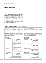
...] VFO is selected. [EXAMPLE] Memory channel 1 is selected from another VFO or memory mode, the last-used frequency and operating mode for split frequency opration. Memory mode is changed . Another memory channel is selected again. Memory channel 1 is selected. The IC-718 VFO can also change the frequency with the tuning dial and select the operating...
...] VFO is selected. [EXAMPLE] Memory channel 1 is selected from another VFO or memory mode, the last-used frequency and operating mode for split frequency opration. Memory mode is changed . Another memory channel is selected again. Memory channel 1 is selected. The IC-718 VFO can also change the frequency with the tuning dial and select the operating...
Instruction Manual
Page 32
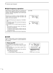
...IC-718 has a built-in circuit of setting 7.057 MHz, CW mode in VFO A (for receive) and 7.025 MHz, CW mode in VFO B (for receive 7.057 MHz/CW and transmit 7.025 MHz/CW. • To change the transmit frequency, rotate the main dial during transmit mode. e Push [MODE] one or more times to transmit; Split... the other in this range. 30 To exchange the transmit and receive frequencies, push [A/B]. 5 RECEIVE AND TRANSMIT s Split frequency operation Split frequency operation allows you to change the receive frequency, rotate the main dial, to transmit and receive on two different...
...IC-718 has a built-in circuit of setting 7.057 MHz, CW mode in VFO A (for receive) and 7.025 MHz, CW mode in VFO B (for receive 7.057 MHz/CW and transmit 7.025 MHz/CW. • To change the transmit frequency, rotate the main dial during transmit mode. e Push [MODE] one or more times to transmit; Split... the other in this range. 30 To exchange the transmit and receive frequencies, push [A/B]. 5 RECEIVE AND TRANSMIT s Split frequency operation Split frequency operation allows you to change the receive frequency, rotate the main dial, to transmit and receive on two different...
Instruction Manual
Page 54
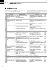
...SPLIT] to turn the function OFF. • Push [P.AMP] to open . • Set [MIC GAIN] to a suitable position. • Turn [COMP] off. • Set [RF/SQL] to the threshold point. • Reset [RF/SQL] control assignment and set it through the use of this chart, contact your nearest Icom... suitable p. 2 speaker. p. 20 p. 21 p. 21 p. 22 • The noise reduction is activated. does not change properly. • A quick set mode screen is selected. • The internal CPU has malfunctioned. • Push [LOCK] to deactivate the function. • Push [SET] to help you are...
...SPLIT] to turn the function OFF. • Push [P.AMP] to open . • Set [MIC GAIN] to a suitable position. • Turn [COMP] off. • Set [RF/SQL] to the threshold point. • Reset [RF/SQL] control assignment and set it through the use of this chart, contact your nearest Icom... suitable p. 2 speaker. p. 20 p. 21 p. 21 p. 22 • The noise reduction is activated. does not change properly. • A quick set mode screen is selected. • The internal CPU has malfunctioned. • Push [LOCK] to deactivate the function. • Push [SET] to help you are...
Instruction Manual
Page 60
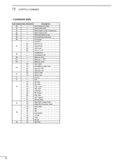
... 0F 01 15 02 02 22 40 16 41 44 46 47 19 00 Description Send frequency data Send mode data Read Upper/Lower frequencies Read frequencies Read operating mode Set operating frequency Set mode Set VFO Set VFO A Set VFO B VFO A=B VFO A # B Set Memory Set Memory CH Memory write Memory $ VFO... Memory clear Scan stop Prog/Memo Scan Start Resume OFF Resume ON SPLIT OFF SPLIT ON Set TS ATT AF Gain RF ...
... 0F 01 15 02 02 22 40 16 41 44 46 47 19 00 Description Send frequency data Send mode data Read Upper/Lower frequencies Read frequencies Read operating mode Set operating frequency Set mode Set VFO Set VFO A Set VFO B VFO A=B VFO A # B Set Memory Set Memory CH Memory write Memory $ VFO... Memory clear Scan stop Prog/Memo Scan Start Resume OFF Resume ON SPLIT OFF SPLIT ON Set TS ATT AF Gain RF ...


