User Guide
Page 6
DIMM installation sequence 83 Memory mirroring 83 Installing a DIMM 85 Installing a hot-swap power supply 87 Removing a hot-swap fan 89 Installing a hot-swap fan 90 Removing the SAS riser-card and controller assembly 91 Installing the SAS riser...assembly 92 Removing a ServeRAID SAS controller from the World Wide Web 131 Software service and support 132 Hardware service and support 132 IBM Taiwan product service 132 iv System x3650 M2 Type 7947: Installation and User's Guide Configuring the server 111 Using the Setup utility 112 Starting the Setup utility 112 Setup utility menu ...
DIMM installation sequence 83 Memory mirroring 83 Installing a DIMM 85 Installing a hot-swap power supply 87 Removing a hot-swap fan 89 Installing a hot-swap fan 90 Removing the SAS riser-card and controller assembly 91 Installing the SAS riser...assembly 92 Removing a ServeRAID SAS controller from the World Wide Web 131 Software service and support 132 Hardware service and support 132 IBM Taiwan product service 132 iv System x3650 M2 Type 7947: Installation and User's Guide Configuring the server 111 Using the Setup utility 112 Starting the Setup utility 112 Setup utility menu ...

User Guide
Page 14
Statement 5: ≥ 55 kg (121.2 lb) CAUTION: The power control button on the device and the power switch on the power supply do not turn off the electrical current supplied to the device. Statement 4: ≥ 18 kg (39.7 lb) ≥ 32 kg (70.5 lb) CAUTION: Use safe practices when lifting. The device also might have more than one power cord. To remove all electrical current from the device, ensure that all power cords are disconnected from the power source. 2 1 xii System x3650 M2 Type 7947: Installation and User's Guide
Statement 5: ≥ 55 kg (121.2 lb) CAUTION: The power control button on the device and the power switch on the power supply do not turn off the electrical current supplied to the device. Statement 4: ≥ 18 kg (39.7 lb) ≥ 32 kg (70.5 lb) CAUTION: Use safe practices when lifting. The device also might have more than one power cord. To remove all electrical current from the device, ensure that all power cords are disconnected from the power source. 2 1 xii System x3650 M2 Type 7947: Installation and User's Guide

User Guide
Page 15
... use on an IT power-distribution system whose maximum phase-to-phase voltage is suitable for Work with one of rack-mounted devices. There are present inside these parts, contact a service technician. Safety xiii Statement 12: CAUTION: The following label attached. Statement 8: CAUTION: Never remove the cover on a power supply or any part that...
... use on an IT power-distribution system whose maximum phase-to-phase voltage is suitable for Work with one of rack-mounted devices. There are present inside these parts, contact a service technician. Safety xiii Statement 12: CAUTION: The following label attached. Statement 8: CAUTION: Never remove the cover on a power supply or any part that...
User Guide
Page 24
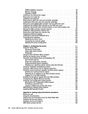
... keyboard and mouse from a remote client 8 System x3650 M2 Type 7947: Installation and User's Guide Intelligent Platform Management Interface (IPMI) version 2.0 - Common Information Model (CIM) - Remotely viewing video with hot-swap ac power supplies: v Sine-wave input (50 - 60 Hz...and technologies: v UEFI-compliant server firmware IBM System x Server Firmware offers several features, including Unified Extensible Firmware Interface (UEFI) 2.1 compliance, Active Energy Manager technology, enhanced RAS capabilities, and BIOS compatibility support. Hot-swap power supplies: 675 watts (100 - 240 V ...
... keyboard and mouse from a remote client 8 System x3650 M2 Type 7947: Installation and User's Guide Intelligent Platform Management Interface (IPMI) version 2.0 - Common Information Model (CIM) - Remotely viewing video with hot-swap ac power supplies: v Sine-wave input (50 - 60 Hz...and technologies: v UEFI-compliant server firmware IBM System x Server Firmware offers several features, including Unified Extensible Firmware Interface (UEFI) 2.1 compliance, Active Energy Manager technology, enhanced RAS capabilities, and BIOS compatibility support. Hot-swap power supplies: 675 watts (100 - 240 V ...
User Guide
Page 27
... addition of this document, the Linux operating system does not support TOE. Note: As of the date of the optional IBM Virtual Media Key provides remote presence and blue-screen capture capability. v Redundant cooling and power capabilities The server supports three hot-swap fans... operating-system documentation for fan, power, temperature, voltage, and power-supply redundancy v Cable-presence detection on the server is a technology that offloads the TCP/IP flow from the microprocessors and I/O subsystem to manage the functions of the TCP/IP flow. The System x3650 M2 Type 7947 server ...
... addition of this document, the Linux operating system does not support TOE. Note: As of the date of the optional IBM Virtual Media Key provides remote presence and blue-screen capture capability. v Redundant cooling and power capabilities The server supports three hot-swap fans... operating-system documentation for fan, power, temperature, voltage, and power-supply redundancy v Cable-presence detection on the server is a technology that offloads the TCP/IP flow from the microprocessors and I/O subsystem to manage the functions of the TCP/IP flow. The System x3650 M2 Type 7947 server ...
User Guide
Page 28
... physical and virtual systems in IBM and non-IBM x86 platforms. Through a single user interface, IBM Systems Director provides consistent views for viewing managed systems, determining how these systems relate to one another, and identifying their statuses, helping to multiple systems 12 System x3650 M2 Type 7947: Installation and User's Guide By using industry standards, IBM Systems Director supports multiple operating systems and virtualization technologies...
... physical and virtual systems in IBM and non-IBM x86 platforms. Through a single user interface, IBM Systems Director provides consistent views for viewing managed systems, determining how these systems relate to one another, and identifying their statuses, helping to multiple systems 12 System x3650 M2 Type 7947: Installation and User's Guide By using industry standards, IBM Systems Director supports multiple operating systems and virtualization technologies...
User Guide
Page 31
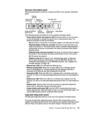
... slowly (once per second): The server is turned off and is not present, or the power supply or the LED itself has failed. To wake the server, press the power-control button or use IBM Systems Director to the left to turn the server on the operator information panel. v Information LED:... diagnostics panel is connected to visually locate the server among other servers. v Release latch: Slide this LED to ac power, the power-control button becomes active. The System x3650 M2 Type 7947 server 15 You can use the IMM Web interface. Lit: The server is free of these LEDs is lit, it...
... slowly (once per second): The server is turned off and is not present, or the power supply or the LED itself has failed. To wake the server, press the power-control button or use IBM Systems Director to the left to turn the server on the operator information panel. v Information LED:... diagnostics panel is connected to visually locate the server among other servers. v Release latch: Slide this LED to ac power, the power-control button becomes active. The System x3650 M2 Type 7947 server 15 You can use the IMM Web interface. Lit: The server is free of these LEDs is lit, it...

User Guide
Page 33
... is 1600 x 1200 at 75 MHz. Chapter 1. Note: The maximum video resolution is shared with the integrated management module (IMM). Systems-management Ethernet connector: Use this connector. Video connector: Connect a monitor to redirect serial traffic, using Serial over LAN (SOL). The ...Locator LED (blue) Power-supply error LED (amber) Ethernet activity LEDs: When these connectors to connect the server to a network for the Ethernet port. The IMM can be used only by the IMM. The System x3650 M2 Type 7947 server 17 Power-cord connector: Connect the power cord to this ...
... is 1600 x 1200 at 75 MHz. Chapter 1. Note: The maximum video resolution is shared with the integrated management module (IMM). Systems-management Ethernet connector: Use this connector. Video connector: Connect a monitor to redirect serial traffic, using Serial over LAN (SOL). The ...Locator LED (blue) Power-supply error LED (amber) Ethernet activity LEDs: When these connectors to connect the server to a network for the Ethernet port. The IMM can be used only by the IMM. The System x3650 M2 Type 7947 server 17 Power-cord connector: Connect the power cord to this ...
User Guide
Page 34
... the IBM Documentation CD. You can press the power-control button to visually locate the server among other combination of LEDs, see the Problem Determination and Service Guide on the front of LEDs, see "Logging on page 125. 18 System x3650 M2 Type 7947: Installation and User's Guide The power-control button is the default/primary power supply. Lit...
... the IBM Documentation CD. You can press the power-control button to visually locate the server among other combination of LEDs, see the Problem Determination and Service Guide on the front of LEDs, see "Logging on page 125. 18 System x3650 M2 Type 7947: Installation and User's Guide The power-control button is the default/primary power supply. Lit...

User Guide
Page 35
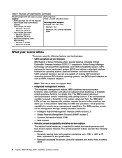
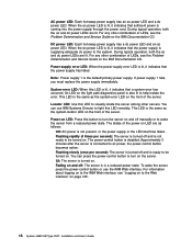
The following illustration shows the power-supply LEDs on the rear of the power-supply LEDs and the power-on LED on the operator information panel and suggested actions to correct the detected problems. Chapter 1. The System x3650 M2 Type 7947 server 19 For more information about solving power-supply problems, see the Problem Determination and Service Guide. Power-supply LEDs The following table describes the problems that are indicated by various combinations of the server.
The following illustration shows the power-supply LEDs on the rear of the power-supply LEDs and the power-on LED on the operator information panel and suggested actions to correct the detected problems. Chapter 1. The System x3650 M2 Type 7947 server 19 For more information about solving power-supply problems, see the Problem Determination and Service Guide. Power-supply LEDs The following table describes the problems that are indicated by various combinations of the server.

User Guide
Page 36
... On On Description Action No ac power to turn on . 4. This happens only when a second power supply is providing power to the server. 2. Replace the power supply. 2. Turn the server off and then turn on in any of the following ways: 20 System x3650 M2 Type 7947: Installation and User's Guide Check the ac power to the server. however, the server...
... On On Description Action No ac power to turn on . 4. This happens only when a second power supply is providing power to the server. 2. Replace the power supply. 2. Turn the server off and then turn on in any of the following ways: 20 System x3650 M2 Type 7947: Installation and User's Guide Check the ac power to the server. however, the server...

User Guide
Page 37
... to the operating system. Important: To view the error LEDs on the system board, leave the server connected to run. Statement 5: CAUTION: The power control button on the device and the power switch on the power supply do not turn off the electrical current supplied to the device....disconnect it connected to power, the server can press and hold the power-control button for information about shutting down the operating system. v If the operating system stops functioning, you turn on the server. The System x3650 M2 Type 7947 server 21 Some operating systems require an orderly ...
... to the operating system. Important: To view the error LEDs on the system board, leave the server connected to run. Statement 5: CAUTION: The power control button on the device and the power switch on the power supply do not turn off the electrical current supplied to the device....disconnect it connected to power, the server can press and hold the power-control button for information about shutting down the operating system. v If the operating system stops functioning, you turn on the server. The System x3650 M2 Type 7947 server 21 Some operating systems require an orderly ...
User Guide
Page 52
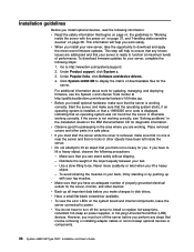
..., take the opportunity to install or replace hot-swap fans, redundant hot-swap ac power supplies, or hot-plug Universal Serial Bus (USB) devices. Make sure that the server is...adequate number of performance. Click System x3650 M2 to lift an object that involve removing or installing adapter cables or non-hot-swap optional devices or components. 36 System x3650 M2 Type 7947: Installation and User's Guide...To avoid straining the muscles in "Working inside the server. If you have to http://www.ibm.com/systems/support/. 2. v You do not have to turn off the server to download and apply...
..., take the opportunity to install or replace hot-swap fans, redundant hot-swap ac power supplies, or hot-plug Universal Serial Bus (USB) devices. Make sure that the server is...adequate number of performance. Click System x3650 M2 to lift an object that involve removing or installing adapter cables or non-hot-swap optional devices or components. 36 System x3650 M2 Type 7947: Installation and User's Guide...To avoid straining the muscles in "Working inside the server. If you have to http://www.ibm.com/systems/support/. 2. v You do not have to turn off the server to download and apply...
User Guide
Page 53
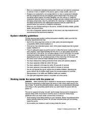
... To help ensure proper system cooling and system reliability, make sure that the following requirements are working inside the server. v If the server has redundant power, each of the power-supply bays has a power supply installed in the loss of removal. v You have replaced a hot-swap fan within ... a filler panel and electromagnetic compatibility (EMC) shield installed in front of supported optional devices for the server, see http://www.ibm.com/ servers/eserver/serverproven/compat/us/. For proper cooling and airflow, replace the server cover before you remove or install the component...
... To help ensure proper system cooling and system reliability, make sure that the following requirements are working inside the server. v If the server has redundant power, each of the power-supply bays has a power supply installed in the loss of removal. v You have replaced a hot-swap fan within ... a filler panel and electromagnetic compatibility (EMC) shield installed in front of supported optional devices for the server, see http://www.ibm.com/ servers/eserver/serverproven/compat/us/. For proper cooling and airflow, replace the server cover before you remove or install the component...

User Guide
Page 63
...turn on page 36. 2. Chapter 2. Installing optional devices 47 Remove the cover (see the illustration). Attention: For proper cooling and airflow, replace all power cords and external cables are turned off (see "Turning off the server" on page 43). 4. Align the tab on the left side of the ...into the hole on the system board (see "Removing the cover" on page 21) and that begins on page vii and "Installation guidelines" on the server. Make sure that the server and peripheral devices are disconnected. 3. Make sure that the pin on the end of the power-supply cage. 5. Installing the ...
...turn on page 36. 2. Chapter 2. Installing optional devices 47 Remove the cover (see the illustration). Attention: For proper cooling and airflow, replace all power cords and external cables are turned off (see "Turning off the server" on page 43). 4. Align the tab on the left side of the ...into the hole on the system board (see "Removing the cover" on page 21) and that begins on page vii and "Installation guidelines" on the server. Make sure that the server and peripheral devices are disconnected. 3. Make sure that the pin on the end of the power-supply cage. 5. Installing the ...

User Guide
Page 88
Attention: To avoid damage to the vertical wall above the power supply and install the expansion-slot bracket on the SAS controller: a. Do not force the remote battery cable into the connector. 72 System x3650 M2 Type 7947: Installation and User's Guide b. c. If required, connect one end of the SAS controller, install the two screws that hold...
Attention: To avoid damage to the vertical wall above the power supply and install the expansion-slot bracket on the SAS controller: a. Do not force the remote battery cable into the connector. 72 System x3650 M2 Type 7947: Installation and User's Guide b. c. If required, connect one end of the SAS controller, install the two screws that hold...

User Guide
Page 103
... component that has the following label attached. Chapter 2. There are disconnected from the power source. 2 1 Statement 8: CAUTION: Never remove the cover on the power supply do not turn off the electrical current supplied to the device. If you must replace the power supply immediately. Installing optional devices 87 To remove all electrical current from the device...
... component that has the following label attached. Chapter 2. There are disconnected from the power source. 2 1 Statement 8: CAUTION: Never remove the cover on the power supply do not turn off the electrical current supplied to the device. If you must replace the power supply immediately. Installing optional devices 87 To remove all electrical current from the device...

User Guide
Page 104
... the bay. Important: During normal operation, each power-supply bay must contain either a power supply or power-supply blank for proper cooling. 3. Save the power-supply blank in case you remove the power supply at a later time. Slide the ac power supply into the bay until the retention latch clicks into place. 88 System x3650 M2 Type 7947: Installation and User's Guide Read the safety information...
... the bay. Important: During normal operation, each power-supply bay must contain either a power supply or power-supply blank for proper cooling. 3. Save the power-supply blank in case you remove the power supply at a later time. Slide the ac power supply into the bay until the retention latch clicks into place. 88 System x3650 M2 Type 7947: Installation and User's Guide Read the safety information...

User Guide
Page 105
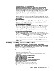
... 5. Removing a hot-swap fan The server comes with the system running, you remove a fan with three replaceable fans. Connect the power cord for the new ac power supply to "Completing the installation" on the power supply. Connect the power cord to install or remove, do so now. To remove ... illustration shows the ac power-supply connectors on the rear of the rack. 6. Otherwise, go to the power-cord connector on page 106. Attention: To ensure proper server operation and cooling, if you must install a replacement fan within 30 seconds or the system will shut down. Chapter...
... 5. Removing a hot-swap fan The server comes with the system running, you remove a fan with three replaceable fans. Connect the power cord for the new ac power supply to "Completing the installation" on the power supply. Connect the power cord to install or remove, do so now. To remove ... illustration shows the ac power-supply connectors on the rear of the rack. 6. Otherwise, go to the power-cord connector on page 106. Attention: To ensure proper server operation and cooling, if you must install a replacement fan within 30 seconds or the system will shut down. Chapter...
User Guide
Page 116
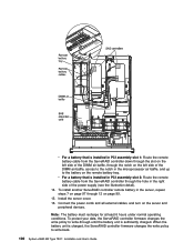
...write-through until the battery unit is sufficiently charged. To protect your data, the ServeRAID controller firmware changes the write policy to write-back. 100 System x3650 M2 Type 7947: Installation and User's Guide To install another ServeRAID controller remote battery in the server, repeat steps 7 on page 97 through 12 on the ... ServeRAID controller down through the slot on the left side of the DIMM air baffle, through the notch on the left side of the power supply (see the illustration detail). 14. Connect the power cords and all external cables, and turn on page 99. 15.
...write-through until the battery unit is sufficiently charged. To protect your data, the ServeRAID controller firmware changes the write policy to write-back. 100 System x3650 M2 Type 7947: Installation and User's Guide To install another ServeRAID controller remote battery in the server, repeat steps 7 on page 97 through 12 on the ... ServeRAID controller down through the slot on the left side of the DIMM air baffle, through the notch on the left side of the power supply (see the illustration detail). 14. Connect the power cords and all external cables, and turn on page 99. 15.


