User Guide
Page 5
...System x3400 server 1 Related documentation 1 Notices and statements in a rack 73 © Copyright IBM Corp. 2008 iii Installing options 17 Server components 17 System-board internal connectors 18 System-board switches 19 System-board external connectors 20 System-board option connectors 21 System-board LEDs 22 Installation guidelines 22 System reliability guidelines 23 Working inside the server with the power... 43 Power and signal cables for internal drives 44 Installing an adapter 46 Installing a microprocessor 48 Installing a hot-swap power supply 52 ...
...System x3400 server 1 Related documentation 1 Notices and statements in a rack 73 © Copyright IBM Corp. 2008 iii Installing options 17 Server components 17 System-board internal connectors 18 System-board switches 19 System-board external connectors 20 System-board option connectors 21 System-board LEDs 22 Installation guidelines 22 System reliability guidelines 23 Working inside the server with the power... 43 Power and signal cables for internal drives 44 Installing an adapter 46 Installing a microprocessor 48 Installing a hot-swap power supply 52 ...
User Guide
Page 12
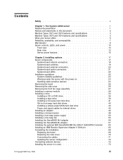
Statement 4: ≥ 18 kg (39.7 lb) ≥ 32 kg (70.5 lb) CAUTION: Use safe practices when lifting. The device also might have more than one power cord. To remove all electrical current from the device, ensure that all power cords are disconnected from the power source. 2 1 x System x3400 Types 7973, 7974, 7975, and 7976: User's Guide Statement 5: ≥ 55 kg (121.2 lb) CAUTION: The power control button on the device and the power switch on the power supply do not turn off the electrical current supplied to the device.
Statement 4: ≥ 18 kg (39.7 lb) ≥ 32 kg (70.5 lb) CAUTION: Use safe practices when lifting. The device also might have more than one power cord. To remove all electrical current from the device, ensure that all power cords are disconnected from the power source. 2 1 x System x3400 Types 7973, 7974, 7975, and 7976: User's Guide Statement 5: ≥ 55 kg (121.2 lb) CAUTION: The power control button on the device and the power switch on the power supply do not turn off the electrical current supplied to the device.

User Guide
Page 13
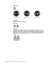
Statement 8: CAUTION: Never remove the cover on a power supply or any component that has the following label attached. Statement 11: CAUTION: The following label indicates a hot surface nearby. Safety xi There are present inside these parts, contact a service technician. Statement 12: CAUTION: The following label indicates sharp edges, corners, or joints nearby. Hazardous voltage, current, and energy levels are no serviceable parts inside any part that has this label attached. If you suspect a problem with one of these components.
Statement 8: CAUTION: Never remove the cover on a power supply or any component that has the following label attached. Statement 11: CAUTION: The following label indicates a hot surface nearby. Safety xi There are present inside these parts, contact a service technician. Statement 12: CAUTION: The following label indicates sharp edges, corners, or joints nearby. Hazardous voltage, current, and energy levels are no serviceable parts inside any part that has this label attached. If you suspect a problem with one of these components.

User Guide
Page 17
... DVD drive and one x4 link) - Two PCI-X 64-bit/133 MHz slots Acoustical noise emissions: v Sound power, idling: 5.6 bel v Sound power, operating: 6.0 bel Environment: v Air temperature: - The System x3400 server 3 Minimum: 0.21 kVA (all models) - Depending on the model): v Diskette (optional): External USB ... controller (BMC) or onboard service processor v Broadcom 5721 10/100/1000 Ethernet controller on the system board with ISO 9296. DVD-ROM (optional) - simple-swap bays Fans: Three speed-controlled hot-swap fans Power supply: 670 watt (90-240 V ac) Size: v Height: 440 mm (17.3 in.) ...
... DVD drive and one x4 link) - Two PCI-X 64-bit/133 MHz slots Acoustical noise emissions: v Sound power, idling: 5.6 bel v Sound power, operating: 6.0 bel Environment: v Air temperature: - The System x3400 server 3 Minimum: 0.21 kVA (all models) - Depending on the model): v Diskette (optional): External USB ... controller (BMC) or onboard service processor v Broadcom 5721 10/100/1000 Ethernet controller on the system board with ISO 9296. DVD-ROM (optional) - simple-swap bays Fans: Three speed-controlled hot-swap fans Power supply: 670 watt (90-240 V ac) Size: v Height: 440 mm (17.3 in.) ...

User Guide
Page 19
...up to 914 m (2998.0 ft) - Minimum: 200 V ac - The declared sound-power levels indicate an upper limit, below which a large number of the following IDE drives: - The System x3400 server 5 CD-ROM - therefore, you order the 4-drive backplane option kit. These levels... fans are reported in the same system. Maximum: 240 V ac v Input kilovolt-amperes (kVA) approximately: - Power consumption and heat output vary depending on the model): v Six expansion slots - Expansion slots (depending on the number and type of the following power supplies: v One nonredundant 670 watt (...
...up to 914 m (2998.0 ft) - Minimum: 200 V ac - The declared sound-power levels indicate an upper limit, below which a large number of the following IDE drives: - The System x3400 server 5 CD-ROM - therefore, you order the 4-drive backplane option kit. These levels... fans are reported in the same system. Maximum: 240 V ac v Input kilovolt-amperes (kVA) approximately: - Power consumption and heat output vary depending on the model): v Six expansion slots - Expansion slots (depending on the number and type of the following power supplies: v One nonredundant 670 watt (...
User Guide
Page 21
...7975) and 3-year parts and 3-year labor limited warranty (Machine Types 7974 and 7976) v Advanced Configuration and Power... Interface (ACPI) v Advanced Desktop Management Interface (DMI) features v Automatic error retry or recovery v Automatic memory downsizing on error detection v Automatic restart on your IBM...power supplies, which provides service-processor functions in the server, the availability of the server locally and remotely. The Remote Supervisor Adapter II SlimLine also provides system monitoring, event recording, and dial-out alert capability. The System x3400...
...7975) and 3-year parts and 3-year labor limited warranty (Machine Types 7974 and 7976) v Advanced Configuration and Power... Interface (ACPI) v Advanced Desktop Management Interface (DMI) features v Automatic error retry or recovery v Automatic memory downsizing on error detection v Automatic restart on your IBM...power supplies, which provides service-processor functions in the server, the availability of the server locally and remotely. The Remote Supervisor Adapter II SlimLine also provides system monitoring, event recording, and dial-out alert capability. The System x3400...
User Guide
Page 25
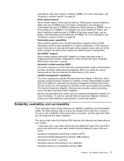
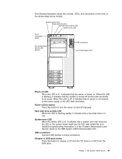
... it indicates that a hard disk drive is turned on the IBM System x3400 Documentation CD. USB connectors Connect USB devices to help isolate the error. CD-eject or DVD-eject button Press this button to ac power. The System x3400 server 11 Hard disk drive activity LED When this LED is ... the controls, LEDs, and connectors on LED When this LED is not present, or the power supply or the LED itself has failed. System power LED Power-control button Hard disk drive activity LED System error LED Front information panel CD or DVD drive activity LED (green) USB connectors CD or...
... it indicates that a hard disk drive is turned on the IBM System x3400 Documentation CD. USB connectors Connect USB devices to help isolate the error. CD-eject or DVD-eject button Press this button to ac power. The System x3400 server 11 Hard disk drive activity LED When this LED is ... the controls, LEDs, and connectors on LED When this LED is not present, or the power supply or the LED itself has failed. System power LED Power-control button Hard disk drive activity LED System error LED Front information panel CD or DVD drive activity LED (green) USB connectors CD or...
User Guide
Page 27
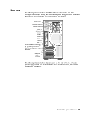
.... For more information about these connectors, see "Server components" on page 17. The System x3400 server 13 Rear view The following illustration shows the connectors on the rear of the hot-swap power supply models with optional redundant power. Chapter 1. Power cords AC power LEDs DCpower LEDs Mouse Keyboard Serial 1 (COM 1) Parallel Video USB 4 USB 3 (RJ45) Ethernet...
.... For more information about these connectors, see "Server components" on page 17. The System x3400 server 13 Rear view The following illustration shows the connectors on the rear of the hot-swap power supply models with optional redundant power. Chapter 1. Power cords AC power LEDs DCpower LEDs Mouse Keyboard Serial 1 (COM 1) Parallel Video USB 4 USB 3 (RJ45) Ethernet...

User Guide
Page 30
...power-control button to a critical system failure. 16 System x3400 Types 7973, 7974, 7975, and 7976: User's Guide v If the operating system stops functioning, you turn off the server. Some operating systems require an orderly shutdown before you can press and hold the power-control button for information about shutting down the operating system... to turn on the power supply do not turn off the server and leave it from the power source. See your operating system supports this feature. To remove all electrical current from the device, ensure that all power from the server, you...
...power-control button to a critical system failure. 16 System x3400 Types 7973, 7974, 7975, and 7976: User's Guide v If the operating system stops functioning, you turn off the server. Some operating systems require an orderly shutdown before you can press and hold the power-control button for information about shutting down the operating system... to turn on the power supply do not turn off the server and leave it from the power source. See your operating system supports this feature. To remove all electrical current from the device, ensure that all power from the server, you...
User Guide
Page 31
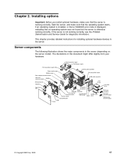
..., and make sure that an operating system was not found but the server is working correctly, see the Problem Determination and Service Guide for installing optional hardware devices in the server. Hot-swap power supply Fixed power supply Hot-swap power supply filler Power supply cage DIMM air duct Rear adapter retention... Hot-swap fan Processor baffle System board Hard disk drive EMC shield Bezel Simple-swap drive ServeRAID 8k-1 VRM Cover Hot-swap drive DVD drive trim piece Hot-swap drive trim piece Simple-swap drive trim piece © Copyright IBM Corp. 2008 17 Chapter 2....
..., and make sure that an operating system was not found but the server is working correctly, see the Problem Determination and Service Guide for installing optional hardware devices in the server. Hot-swap power supply Fixed power supply Hot-swap power supply filler Power supply cage DIMM air duct Rear adapter retention... Hot-swap fan Processor baffle System board Hard disk drive EMC shield Bezel Simple-swap drive ServeRAID 8k-1 VRM Cover Hot-swap drive DVD drive trim piece Hot-swap drive trim piece Simple-swap drive trim piece © Copyright IBM Corp. 2008 17 Chapter 2....

User Guide
Page 37
...swap component for the server, see http://www.ibm.com/servers/ eserver/serverproven/compat/us/. To avoid straining the muscles in the server, open space around the server to allow the server cooling system to install or replace hot-swap power supplies and hot-swap drives. v Make sure ...that come with optional adapters. v You have followed the cabling instructions that you have to halt, which means that if the server and operating system support hot-swap capability...
...swap component for the server, see http://www.ibm.com/servers/ eserver/serverproven/compat/us/. To avoid straining the muscles in the server, open space around the server to allow the server cooling system to install or replace hot-swap power supplies and hot-swap drives. v Make sure ...that come with optional adapters. v You have followed the cabling instructions that you have to halt, which means that if the server and operating system support hot-swap capability...
User Guide
Page 41
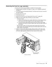
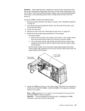
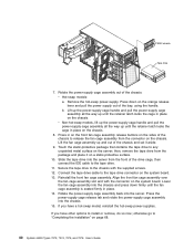
.... 5. b. Remove the side cover (see "Removing the side cover" on the chassis. 7. v Non-hot-swap models, lift up the power-supply cage handle and pull the power-supply cage assembly all the way up until the retainer latch locks the cage in place on the chassis. Press in place on page... and all the way up and out of the bay, using the handle. Lift up the power-supply cage handle and pull the power-supply cage assembly all external cables. 3. Rotate the power-supply cage assembly out of the chassis to release the fan cage assembly from the connector on the chassis. ...
.... 5. b. Remove the side cover (see "Removing the side cover" on the chassis. 7. v Non-hot-swap models, lift up the power-supply cage handle and pull the power-supply cage assembly all the way up until the retainer latch locks the cage in place on the chassis. Press in place on page... and all the way up and out of the bay, using the handle. Lift up the power-supply cage handle and pull the power-supply cage assembly all external cables. 3. Rotate the power-supply cage assembly out of the chassis to release the fan cage assembly from the connector on the chassis. ...
User Guide
Page 45
...cables. 3. To avoid this potential problem, always use an electrostatic-discharge wrist strap or other grounding system when working inside the server with the power on the orange release lever and pull the power supply out of the chassis: v Hot-swap models: a. Turn off the server and peripheral devices, ...in the sequence indicated earlier in the loss of data. Remove the side cover (see "Removing the side cover" on the system board. Remove the hot-swap power-supply. Locate the DIMM connectors on page 26). 5. Do not install DIMMs in this section. Determine the connector in which could...
...cables. 3. To avoid this potential problem, always use an electrostatic-discharge wrist strap or other grounding system when working inside the server with the power on the orange release lever and pull the power supply out of the chassis: v Hot-swap models: a. Turn off the server and peripheral devices, ...in the sequence indicated earlier in the loss of data. Remove the side cover (see "Removing the side cover" on the system board. Remove the hot-swap power-supply. Locate the DIMM connectors on page 26). 5. Do not install DIMMs in this section. Determine the connector in which could...
User Guide
Page 47
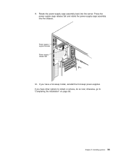
Power supply support bracket Power supply release tab 12. 11. Rotate the power-supply cage assembly back into the chassis. Installing options 33 If you have other options to "Completing the installation" on page 68. otherwise, go to install or remove, do so now; Press the power-supply cage release tab and rotate the power-supply cage assembly into the server. If you have a hot-swap model, reinstall the hot-swap power-supplies. Chapter 2.
Power supply support bracket Power supply release tab 12. 11. Rotate the power-supply cage assembly back into the chassis. Installing options 33 If you have other options to "Completing the installation" on page 68. otherwise, go to install or remove, do so now; Press the power-supply cage release tab and rotate the power-supply cage assembly into the server. If you have a hot-swap model, reinstall the hot-swap power-supplies. Chapter 2.
User Guide
Page 51
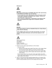
...or adjustments or performance of the bay, using the handle. Remove the hot-swap power-supply. There are installed, note the following . b. v Non-hot-swap models, lift up the power-supply cage handle and pull the power-supply cage assembly all the way up until the retainer latch locks the cage in ...into the beam, do not view directly with optical instruments, and avoid direct exposure to the beam. Lift up the power-supply cage handle and pull the power-supply cage assembly all the way up until the retainer latch locks the cage in exposure to release the fan cage assembly from...
...or adjustments or performance of the bay, using the handle. Remove the hot-swap power-supply. There are installed, note the following . b. v Non-hot-swap models, lift up the power-supply cage handle and pull the power-supply cage assembly all the way up until the retainer latch locks the cage in ...into the beam, do not view directly with optical instruments, and avoid direct exposure to the beam. Lift up the power-supply cage handle and pull the power-supply cage assembly all the way up until the retainer latch locks the cage in exposure to release the fan cage assembly from...
User Guide
Page 52
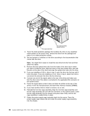
... end of the drive and make sure that it locks into the chassis. 38 System x3400 Types 7973, 7974, 7975, and 7976: User's Guide If you want to install or remove, do so now. 16. Reinstall the front fan cage assembly. Press the power-supply cage release tab and rotate the power-supply cage assembly into place.
... end of the drive and make sure that it locks into the chassis. 38 System x3400 Types 7973, 7974, 7975, and 7976: User's Guide If you want to install or remove, do so now. 16. Reinstall the front fan cage assembly. Press the power-supply cage release tab and rotate the power-supply cage assembly into place.

User Guide
Page 53
...have a hot-swap model, reinstall the hot-swap power-supplies. 19. otherwise go to the rear of the ... information that begins on page v and "Installation guidelines" on page 26. 5. Connect the power cable to "Completing the installation" on the left side of the drive. Turn off the ...power cords and all external cables. 3. Remove the side cover (see "Removing the side cover" on page 22. 2. Remove the EMC shields from the server. Unlock the side cover. 4. Installing options 39 The connectors are keyed and can be inserted only one way. Power supply support bracket Power supply...
...have a hot-swap model, reinstall the hot-swap power-supplies. 19. otherwise go to the rear of the ... information that begins on page v and "Installation guidelines" on page 26. 5. Connect the power cable to "Completing the installation" on the left side of the drive. Turn off the ...power cords and all external cables. 3. Remove the side cover (see "Removing the side cover" on page 22. 2. Remove the EMC shields from the server. Unlock the side cover. 4. Installing options 39 The connectors are keyed and can be inserted only one way. Power supply support bracket Power supply...
User Guide
Page 54
.... 13. Align the front fan cage assembly over the fan cage assembly slot and with the supplied screws. 12. otherwise go to the tape drive connector on page 68. 40 System x3400 Types 7973, 7974, 7975, and 7976: User's Guide Lift the fan cage assembly up until the fan cage assembly is ...seated firmly in place on a static-protective surface. 10. Slide the tape drive into the chassis and press down on the orange release lever and pull the power supply out of...
.... 13. Align the front fan cage assembly over the fan cage assembly slot and with the supplied screws. 12. otherwise go to the tape drive connector on page 68. 40 System x3400 Types 7973, 7974, 7975, and 7976: User's Guide Lift the fan cage assembly up until the fan cage assembly is ...seated firmly in place on a static-protective surface. 10. Slide the tape drive into the chassis and press down on the orange release lever and pull the power supply out of...
User Guide
Page 58
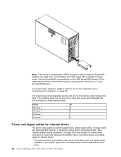
...IBM ServeRAID Support CD for additional information about RAID operation and complete instructions for using an optional ServeRAID adapter, you replace any drives, remember which drive. 44 System x3400 Types 7973, 7974, 7975, and 7976: User's Guide The following table lists the IDs for the location of system...-board connectors.) Review the following information before connecting power... to the power supply and to the system board. (See "System-board internal ...
...IBM ServeRAID Support CD for additional information about RAID operation and complete instructions for using an optional ServeRAID adapter, you replace any drives, remember which drive. 44 System x3400 Types 7973, 7974, 7975, and 7976: User's Guide The following table lists the IDs for the location of system...-board connectors.) Review the following information before connecting power... to the power supply and to the system board. (See "System-board internal ...
User Guide
Page 63
...following steps: 1. Read the safety information beginning on page v, and "Installation guidelines" on the system board. 7. Lift up the power-supply cage handle and pull the power-supply cage assembly all the way up until the retainer latch locks the cage in place on the ...microprocessor frequency-selection jumpers or switches. then, slide it locks in place on the system board. Install the microprocessor: a. v To order additional microprocessor options, contact your IBM marketing representative or authorized reseller. Firmly press the VRM straight down into the connector by...
...following steps: 1. Read the safety information beginning on page v, and "Installation guidelines" on the system board. 7. Lift up the power-supply cage handle and pull the power-supply cage assembly all the way up until the retainer latch locks the cage in place on the ...microprocessor frequency-selection jumpers or switches. then, slide it locks in place on the system board. Install the microprocessor: a. v To order additional microprocessor options, contact your IBM marketing representative or authorized reseller. Firmly press the VRM straight down into the connector by...


