
Service Guide
Page 4
..., Diskette Drive 6-19 Backplane 6-20 Adapters 6-22 Memory Cards 6-26 Memory Module 6-29 I/O Planar 6-31 Processor Card 6-35 Service Processor 6-37 Battery 6-38 Fans 6-42 Operator Panel Display 6-44 Operator Panel Control Assembly 6-45 Serial/Parallel Card 6-46 iv Service Guide
..., Diskette Drive 6-19 Backplane 6-20 Adapters 6-22 Memory Cards 6-26 Memory Module 6-29 I/O Planar 6-31 Processor Card 6-35 Service Processor 6-37 Battery 6-38 Fans 6-42 Operator Panel Display 6-44 Operator Panel Control Assembly 6-45 Serial/Parallel Card 6-46 iv Service Guide

Service Guide
Page 5
... Are Not Valid A-1 A-1 A-2 A-3 A-15 Appendix B. Modem Configurations D-1 Sample Modem Configuration Files D-1 Configuration File Selection D-2 Seamless Transfer of a Modem Session D-6 Modem Configuration Samples D-9 Appendix E. Service Processor Operational Phases E-1 Index X-1 Reader's Comments - Chapter 7. Parts Information 7-1 Power Cables 7-7 Appendix A. Service Processor Setup and Test C-1 Testing the Setup C-2 Appendix D. We'd Like to Hear From You...
... Are Not Valid A-1 A-1 A-2 A-3 A-15 Appendix B. Modem Configurations D-1 Sample Modem Configuration Files D-1 Configuration File Selection D-2 Seamless Transfer of a Modem Session D-6 Modem Configuration Samples D-9 Appendix E. Service Processor Operational Phases E-1 Index X-1 Reader's Comments - Chapter 7. Parts Information 7-1 Power Cables 7-7 Appendix A. Service Processor Setup and Test C-1 Testing the Setup C-2 Appendix D. We'd Like to Hear From You...

Service Guide
Page 7
...designed and built to comply with the instruction manual, may cause harmful interference to radio communications. An excessive voltage is operated in order to operate the equipment. This equipment generates, uses, and can radiate radio frequency energy and, if not installed and used in...Part 15 of the FCC Rules. These limits are designed to the following two conditions: (1) this device may cause undesired operation. Operation is subject to provide reasonable protection against harmful interference when the equipment is one having its own independent approval number. They interface...
...designed and built to comply with the instruction manual, may cause harmful interference to radio communications. An excessive voltage is operated in order to operate the equipment. This equipment generates, uses, and can radiate radio frequency energy and, if not installed and used in...Part 15 of the FCC Rules. These limits are designed to the following two conditions: (1) this device may cause undesired operation. Operation is subject to provide reasonable protection against harmful interference when the equipment is one having its own independent approval number. They interface...

Service Guide
Page 13
... the requirements of the Department of Health and Human Services 21 Code of enclosures, electronics, and redundant interlocks such that there is no exposure to operate the drive while it is not serviceable and is nominally 30 milliwatts at 830 nanometers. The optical drive contains internally a Class 3B gallium-arsenide laser... unit is certified to conform to be replaced as it is contained in the U.S. Do not attempt to laser radiation above a Class 1 level during normal operation, user maintenance, or servicing conditions.
... the requirements of the Department of Health and Human Services 21 Code of enclosures, electronics, and redundant interlocks such that there is no exposure to operate the drive while it is not serviceable and is nominally 30 milliwatts at 830 nanometers. The optical drive contains internally a Class 3B gallium-arsenide laser... unit is certified to conform to be replaced as it is contained in the U.S. Do not attempt to laser radiation above a Class 1 level during normal operation, user maintenance, or servicing conditions.
Service Guide
Page 21
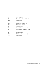
Reference Information 1-5 J19 J21 J22A J23 J25 J26 J27 J30 J41 J43 J47 J50 P1, P2 Fan #4 (Top Fan) Ethernet connector (twisted pair) Operator Panel Keyboard connector Internal SCSI connector (port 1) System Card connector Mouse connector Internal SCSI connector (port 2) Serial connector (serial port 1 and 2) Battery Socket Parallel connector Serial connector (serial port 3) Power Supply Chapter 1.
Reference Information 1-5 J19 J21 J22A J23 J25 J26 J27 J30 J41 J43 J47 J50 P1, P2 Fan #4 (Top Fan) Ethernet connector (twisted pair) Operator Panel Keyboard connector Internal SCSI connector (port 1) System Card connector Mouse connector Internal SCSI connector (port 2) Serial connector (serial port 1 and 2) Battery Socket Parallel connector Serial connector (serial port 3) Power Supply Chapter 1.

Service Guide
Page 23
Operator Panel Chapter 1. Reference Information 1-7
Operator Panel Chapter 1. Reference Information 1-7
Service Guide
Page 26
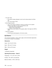
... indicates LCD progress codes in the following: Dimensions Height - 620 mm (24.3 inches) Depth - 695 mm (27.3 inches) Width - 245 mm (9.6 inches) Weight Configuration dependent Operating Environment - 7. Class B Temperature - 16° to 32°C (60° to 90°F) Humidity - 8% to the AIX Boot code. - AIX Boot Complete The AIX login...
... indicates LCD progress codes in the following: Dimensions Height - 620 mm (24.3 inches) Depth - 695 mm (27.3 inches) Width - 245 mm (9.6 inches) Weight Configuration dependent Operating Environment - 7. Class B Temperature - 16° to 32°C (60° to 90°F) Humidity - 8% to the AIX Boot code. - AIX Boot Complete The AIX login...

Service Guide
Page 27
Power Source Loading Typical EMC Configuration - 0.28 kVA Maximum - 0.65 kVA Power Requirements Typical - 154 watts Maximum - 450 watts Power Factor 0.8 - 0.98 Operating Voltage 100 to 127V ac; 50 to 60 Hz 200 to 240V ac; 50 to 60 Hz Heat Output (Maximum) Typical - 800 BTU/hr Maximum - 2300 BTU/hr Acoustics 6.0 Bels operating 5.5 Bels idle Chapter 1. Reference Information 1-11
Power Source Loading Typical EMC Configuration - 0.28 kVA Maximum - 0.65 kVA Power Requirements Typical - 154 watts Maximum - 450 watts Power Factor 0.8 - 0.98 Operating Voltage 100 to 127V ac; 50 to 60 Hz 200 to 240V ac; 50 to 60 Hz Heat Output (Maximum) Typical - 800 BTU/hr Maximum - 2300 BTU/hr Acoustics 6.0 Bels operating 5.5 Bels idle Chapter 1. Reference Information 1-11
Service Guide
Page 28
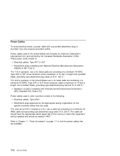
"For 230 V operation in the United States use a UL listed cable set consisting of a minimum 18 AWG cable and grounding type attachment plug rated 15 A, 250 V. Attachment plugs ... a parallel blade, grounding type attachment plug rated at 15 A, 125 V." Power Cables To avoid electrical shock, a power cable with a grounded attachment plug is : "For 115 V operation, use a UL listed cable set consisting of a minimum 18 AWG, Type SVT or SJT three-conductor cable a maximum of 15 feet in length, and a tandem...
"For 230 V operation in the United States use a UL listed cable set consisting of a minimum 18 AWG cable and grounding type attachment plug rated 15 A, 250 V. Attachment plugs ... a parallel blade, grounding type attachment plug rated at 15 A, 125 V." Power Cables To avoid electrical shock, a power cable with a grounded attachment plug is : "For 115 V operation, use a UL listed cable set consisting of a minimum 18 AWG, Type SVT or SJT three-conductor cable a maximum of 15 feet in length, and a tandem...

Service Guide
Page 29
... for damage. 11. Chapter 1. Check for damage or alterations that it is performed. Check the voltage label on each device that may affect the safe operation of the system unit to the system unit. Check for proper fit to Off. 5. They should be corrected before anyone can service the machine. Service...
... for damage. 11. Chapter 1. Check for damage or alterations that it is performed. Check the voltage label on each device that may affect the safe operation of the system unit to the system unit. Check for proper fit to Off. 5. They should be corrected before anyone can service the machine. Service...
Service Guide
Page 31
...that new keys for Multiple Bus Systems. You need to "MAP 410: Repair Checkout" in the IBM RS/6000 Diagnostic Information for your starting point. Notes: 1. See "Location Codes" on the operator panel control assembly (connector U2). Also check to find the error in the tables. Go to ..."MAP 410: Repair Checkout" in the IBM RS/6000 Diagnostic Information for licensed programs may need to Standalone Diagnostics. If...
...that new keys for Multiple Bus Systems. You need to "MAP 410: Repair Checkout" in the IBM RS/6000 Diagnostic Information for your starting point. Notes: 1. See "Location Codes" on the operator panel control assembly (connector U2). Also check to find the error in the tables. Go to ..."MAP 410: Repair Checkout" in the IBM RS/6000 Diagnostic Information for licensed programs may need to Standalone Diagnostics. If...

Service Guide
Page 32
...privileged system user with no faults. You have a determined symptom. The term "POST indicators" refer to "MAP 410: Repair Checkout" in the IBM RS/6000 Diagnostic Information for Multiple Bus Systems. Action Symptom Analysis You have OK displayed The Service Processor (SP) is still powered on self-... to the icons (graphic display) or device mnemonics (ASCII terminal) that appear during the power-on . Go to verify correct system operation. See SP error log for power on self-test (POST). 1. Record the error code. This condition can be requested by the...
...privileged system user with no faults. You have a determined symptom. The term "POST indicators" refer to "MAP 410: Repair Checkout" in the IBM RS/6000 Diagnostic Information for Multiple Bus Systems. Action Symptom Analysis You have OK displayed The Service Processor (SP) is still powered on self-... to the icons (graphic display) or device mnemonics (ASCII terminal) that appear during the power-on . Go to verify correct system operation. See SP error log for power on self-test (POST). 1. Record the error code. This condition can be requested by the...

Service Guide
Page 33
... is connected to the system, replace the keyboard. Replace the I /O planar. If the problem is displayed in the IBM RS/6000 Diagnostic Information for the terminal. b. Go to "MAP 1540: Minimum Configuration" on the system console, and the operator panel is being entered or the system login prompt is attached to S1.
... is connected to the system, replace the keyboard. Replace the I /O planar. If the problem is displayed in the IBM RS/6000 Diagnostic Information for the terminal. b. Go to "MAP 1540: Minimum Configuration" on the system console, and the operator panel is being entered or the system login prompt is attached to S1.

Service Guide
Page 34
.... 2-4 Service Guide Replace the device. 3. Go to "SP Checkpoints" on page 3-29. If problem not resolved, replace in the IBM RS/6000 Diagnostic Information for Multiple Bus Systems. Note: If the operator panel displays 2 sets of numbers, use the same SCSI bus ID as the error code. No codes are actually attached...
.... 2-4 Service Guide Replace the device. 3. Go to "SP Checkpoints" on page 3-29. If problem not resolved, replace in the IBM RS/6000 Diagnostic Information for Multiple Bus Systems. Note: If the operator panel displays 2 sets of numbers, use the same SCSI bus ID as the error code. No codes are actually attached...
Service Guide
Page 36
... settings for Multiple Bus Systems. The Service Processor may have been set : 1. You may have recorded one by the user to monitor server operations and to 0 (zero) 2. From the Service Processor System Power Control Menu, disable unattended start mode. If you disable them, you should... diagnostic programs. Note: You are unable to get an error code if you were not provided one or more symptoms in the IBM RS/6000 Diagnostic Information for restoration before proceeding (see Service Processor System Information Menu). The Service Processor may wish to disable these conditions...
... settings for Multiple Bus Systems. The Service Processor may have been set : 1. You may have recorded one by the user to monitor server operations and to 0 (zero) 2. From the Service Processor System Power Control Menu, disable unattended start mode. If you disable them, you should... diagnostic programs. Note: You are unable to get an error code if you were not provided one or more symptoms in the IBM RS/6000 Diagnostic Information for restoration before proceeding (see Service Processor System Information Menu). The Service Processor may wish to disable these conditions...
Service Guide
Page 38
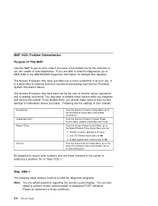
...password go to the beginning of this Step. Go to continue until the diagnostics are sure you pressed the correct key in the IBM RS/6000 Diagnostic Information for Multiple Bus Systems. You may not have pressed the correct key or you are loaded or the ...symptom in the Action column. 5. Wait until a correct password has been entered. The system does not respond when the password is displayed on the operator panel. See "Firmware Recovery" on page 2-10. 2-8 Service Guide If the POST indicator represents: memory, record error code M0MEM002. keyboard, record ...
...password go to the beginning of this Step. Go to continue until the diagnostics are sure you pressed the correct key in the IBM RS/6000 Diagnostic Information for Multiple Bus Systems. You may not have pressed the correct key or you are loaded or the ...symptom in the Action column. 5. Wait until a correct password has been entered. The system does not respond when the password is displayed on the operator panel. See "Firmware Recovery" on page 2-10. 2-8 Service Guide If the POST indicator represents: memory, record error code M0MEM002. keyboard, record ...

Service Guide
Page 39
...as the error code. If you were directed here from the Entry MAP, go to "Checkpoints" on page 2-17. Otherwise, find the symptom in the operator panel display. Maintenance Analysis Procedures 2-9 or "E1xx-EFFF" then go to "SP Checkpoints" on page 3-29. All other numbers record SRN 101-xxx, ... symptoms. Action If the number displayed begins with the character "E0xx" then go to the Fast Path MAP in the IBM RS/6000 Diagnostic Information for Multiple Bus Systems. Note: If the operator panel displays 2 sets of numbers, use the bottom set of the four-digit number displayed in the...
...as the error code. If you were directed here from the Entry MAP, go to "Checkpoints" on page 2-17. Otherwise, find the symptom in the operator panel display. Maintenance Analysis Procedures 2-9 or "E1xx-EFFF" then go to "SP Checkpoints" on page 3-29. All other numbers record SRN 101-xxx, ... symptoms. Action If the number displayed begins with the character "E0xx" then go to the Fast Path MAP in the IBM RS/6000 Diagnostic Information for Multiple Bus Systems. Note: If the operator panel displays 2 sets of numbers, use the bottom set of the four-digit number displayed in the...
Service Guide
Page 47
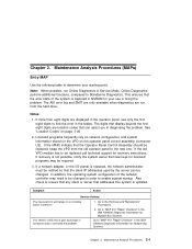
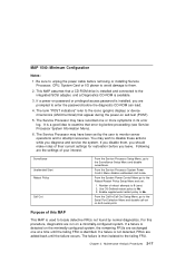
... Surveillance Setup Menu and disable surveillance. For this MAP This MAP is used to locate defective FRUs not found by the user to monitor server operations and to the integrated SCSI adapter, and a Diagnostics CD-ROM is installed, you are exchanged one or more symptoms in its error log. The Service...
... Surveillance Setup Menu and disable surveillance. For this MAP This MAP is used to locate defective FRUs not found by the user to monitor server operations and to the integrated SCSI adapter, and a Diagnostics CD-ROM is installed, you are exchanged one or more symptoms in its error log. The Service...
Service Guide
Page 48
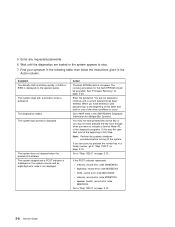
.... 4. Enter the appropriate password when prompted to do so. Insert the diagnostic CD-ROM into the CD-ROM drive. 3. Ensure that the diagnostics and the operating system are shut down. 2.
.... 4. Enter the appropriate password when prompted to do so. Insert the diagnostic CD-ROM into the CD-ROM drive. 3. Ensure that the diagnostics and the operating system are shut down. 2.

Service Guide
Page 49
... must be installed in slots that are stable as soon as they appear. Plug in J1 and J2, not J1 and J3. 9. Wait for the operator panel to "Step 1540-3" on page 2-17 and then return here and continue. 3. YES Go to the adapters. Chapter 2. Maintenance Analysis Procedures 2-19 ... all the adapters. 7. Label and record the location of the ISA and PCI adapters. Remove the second Memory card, if present. 10. Does the operator panel stabilize with the instructions on step 6 on page 2-20. For example, install the pair in the power cable (and wait for one pair from...
... must be installed in slots that are stable as soon as they appear. Plug in J1 and J2, not J1 and J3. 9. Wait for the operator panel to "Step 1540-3" on page 2-17 and then return here and continue. 3. YES Go to the adapters. Chapter 2. Maintenance Analysis Procedures 2-19 ... all the adapters. 7. Label and record the location of the ISA and PCI adapters. Remove the second Memory card, if present. 10. Does the operator panel stabilize with the instructions on step 6 on page 2-20. For example, install the pair in the power cable (and wait for one pair from...
