

Service Guide
Page 2
Changes are inconsistent with IBM Corp. these products, programming, or services will be announced in your country. Such references or information must not be made to the information herein; Requests ...
Changes are inconsistent with IBM Corp. these products, programming, or services will be announced in your country. Such references or information must not be made to the information herein; Requests ...
Service Guide
Page 3
Error Code to FRU Index 3-1 Firmware/POST Error Codes 3-2 Bus SRN to FRU Reference Table 3-27 Checkpoints 3-29 Location Codes 3-46 Preface iii Maintenance Analysis Procedures (MAPs 2-1 Entry MAP 2-1 MAP 1020: Problem Determination 2-6 MAP 1520: Power 2-12 MAP 1540: Minimum Configuration 2-17 SSA Maintenance Analysis Procedures (MAPs 2-35 MAP 2010: SSA Hot-Swap Disk Drive-Start 2-37 Chapter 3. Reference Information 1-1 System Unit Locations 1-1 System Data Flow 1-8 Typical Boot Sequence for Germany ix European Union (EU) Statement x VCCI Statement x Safety Notices xi...
Error Code to FRU Index 3-1 Firmware/POST Error Codes 3-2 Bus SRN to FRU Reference Table 3-27 Checkpoints 3-29 Location Codes 3-46 Preface iii Maintenance Analysis Procedures (MAPs 2-1 Entry MAP 2-1 MAP 1020: Problem Determination 2-6 MAP 1520: Power 2-12 MAP 1540: Minimum Configuration 2-17 SSA Maintenance Analysis Procedures (MAPs 2-35 MAP 2010: SSA Hot-Swap Disk Drive-Start 2-37 Chapter 3. Reference Information 1-1 System Unit Locations 1-1 System Data Flow 1-8 Typical Boot Sequence for Germany ix European Union (EU) Statement x VCCI Statement x Safety Notices xi...
Service Guide
Page 4
Loading the System Diagnostics 4-1 Chapter 5. System Management Services 5-1 Graphical System Management Services 5-1 Config 5-5 MultiBoot 5-7 Utilities 5-10 Password 5-12 Error Log 5-16 RIPL 5-17 SCSI ID 5-21 Update 5-22 Text-Based System Management Services 5-24 Chapter 6. Removal and Replacement Procedures 6-1 Handling Static-Sensitive Devices 6-2 Covers 6-3 Power Supply 6-15 CD-ROM Drive, Tape Drive, Diskette Drive 6-19 Backplane 6-20 Adapters 6-22 Memory Cards 6-26 Memory Module 6-29 I/O Planar 6-31 Processor Card 6-35 Service Processor 6-37 Battery 6-38 ...
Loading the System Diagnostics 4-1 Chapter 5. System Management Services 5-1 Graphical System Management Services 5-1 Config 5-5 MultiBoot 5-7 Utilities 5-10 Password 5-12 Error Log 5-16 RIPL 5-17 SCSI ID 5-21 Update 5-22 Text-Based System Management Services 5-24 Chapter 6. Removal and Replacement Procedures 6-1 Handling Static-Sensitive Devices 6-2 Covers 6-3 Power Supply 6-15 CD-ROM Drive, Tape Drive, Diskette Drive 6-19 Backplane 6-20 Adapters 6-22 Memory Cards 6-26 Memory Module 6-29 I/O Planar 6-31 Processor Card 6-35 Service Processor 6-37 Battery 6-38 ...

Service Guide
Page 5
Chapter 7. SSA Problem Determination Procedures Disk Drive Module Power-On Self-Tests (POSTs Adapter Power-On Self-Tests (POSTs Service Request Numbers (SRNs SSA Loop Configurations That Are Not Valid A-1 A-1 A-2 A-3 A-15 Appendix B. Service Processor Setup and Test C-1 Testing the Setup C-2 Appendix D. Modem Configurations D-1 Sample Modem Configuration Files D-1 Configuration File Selection D-2 Seamless Transfer of a Modem Session D-6 Modem Configuration Samples D-9 Appendix E. Service Processor Operational Phases E-1 Index X-1 Reader's Comments - Service ...
Chapter 7. SSA Problem Determination Procedures Disk Drive Module Power-On Self-Tests (POSTs Adapter Power-On Self-Tests (POSTs Service Request Numbers (SRNs SSA Loop Configurations That Are Not Valid A-1 A-1 A-2 A-3 A-15 Appendix B. Service Processor Setup and Test C-1 Testing the Setup C-2 Appendix D. Modem Configurations D-1 Sample Modem Configuration Files D-1 Configuration File Selection D-2 Seamless Transfer of a Modem Session D-6 Modem Configuration Samples D-9 Appendix E. Service Processor Operational Phases E-1 Index X-1 Reader's Comments - Service ...

Service Guide
Page 7
Unauthorized changes or modifications could void the user's authority to maintain the separate (independent) approval of the FCC Rules. Operation is subject to the following two conditions: (1) this device may not cause harmful interference,and (2) this equipment using other than recommended cables and connectors or by unauthorized changes or modifications to this equipment are approved separately, each one which case the user will be used in accordance with the limits for a Class A digital device, pursuant to Part 15 of this equipment in a residential area is essential that may...
Unauthorized changes or modifications could void the user's authority to maintain the separate (independent) approval of the FCC Rules. Operation is subject to the following two conditions: (1) this device may not cause harmful interference,and (2) this equipment using other than recommended cables and connectors or by unauthorized changes or modifications to this equipment are approved separately, each one which case the user will be used in accordance with the limits for a Class A digital device, pursuant to Part 15 of this equipment in a residential area is essential that may...

Service Guide
Page 8
This product has been tested and found to comply with the limits for typical residential environments to CISPR 22 / European Standard EN 55022. Avis de conformité aux normes du ministère des Communications du Canada Cet appareil numérique de la classe A respecte toutes les exigences du Réglement sur le matériel brouilleur du Canada. The limits for Class B equipment were derived for Class B Information Technology Equipment according to provide reasonable protection against interference with the protection requirements of EU Council Directive 89/336/EEC on the ...
This product has been tested and found to comply with the limits for typical residential environments to CISPR 22 / European Standard EN 55022. Avis de conformité aux normes du ministère des Communications du Canada Cet appareil numérique de la classe A respecte toutes les exigences du Réglement sur le matériel brouilleur du Canada. The limits for Class B equipment were derived for Class B Information Technology Equipment according to provide reasonable protection against interference with the protection requirements of EU Council Directive 89/336/EEC on the ...

Service Guide
Page 9
... for correct handling. Dieses Gerät erfüllt die Bedingungen der EN 55022 Klasse B. Der Aussteller der Konformitätserklärung ist die IBM Germany. Radio Protection for Germany Dieses Gerät ist berechtigt in a domestic environment, it may cause radio interference. This is used near a radio or television...
... for correct handling. Dieses Gerät erfüllt die Bedingungen der EN 55022 Klasse B. Der Aussteller der Konformitätserklärung ist die IBM Germany. Radio Protection for Germany Dieses Gerät ist berechtigt in a domestic environment, it may cause radio interference. This is used near a radio or television...
Service Guide
Page 10
VCCI Statement The following statement applies: European Union (EU) Statement This product is in the box above. x Service Guide The limits for Class A equipment were derived for Interference by third parties. Attention: This is a summary of the VCCI Japanese statement in conformity with the protection requirements of EU Council Directive 89/336/EEC on your dealer or sales representative for any failure to satisfy the protection requirements resulting from a non-recommended modification of the product, including the fitting of option cards supplied by Information Technology ...
VCCI Statement The following statement applies: European Union (EU) Statement This product is in the box above. x Service Guide The limits for Class A equipment were derived for Interference by third parties. Attention: This is a summary of the VCCI Japanese statement in conformity with the protection requirements of EU Council Directive 89/336/EEC on your dealer or sales representative for any failure to satisfy the protection requirements resulting from a non-recommended modification of the product, including the fitting of option cards supplied by Information Technology ...

Service Guide
Page 11
A caution notice indicates the presence of a hazard that has the potential of causing death or serious personal injury. Use this power cable with different electrical potentials. Preface xi Electrical Safety Observe the following safety instructions any additional devices to or from the existing system before the signal cables are connected. When adding or removing any time you add a device. During an electrical storm, do not connect cables for display stations, printers, telephones, or station protectors for the user's safety. DANGER An electrical outlet that is correctly ...
A caution notice indicates the presence of a hazard that has the potential of causing death or serious personal injury. Use this power cable with different electrical potentials. Preface xi Electrical Safety Observe the following safety instructions any additional devices to or from the existing system before the signal cables are connected. When adding or removing any time you add a device. During an electrical storm, do not connect cables for display stations, printers, telephones, or station protectors for the user's safety. DANGER An electrical outlet that is correctly ...

Service Guide
Page 12
xii Service Guide DANGER To prevent electrical shock hazard, disconnect the power cable from the electrical outlet before relocating the system.
xii Service Guide DANGER To prevent electrical shock hazard, disconnect the power cable from the electrical outlet before relocating the system.

Service Guide
Page 13
Do not attempt to open the covers of the drive as a unit. The design incorporates a combination of enclosures, electronics, and redundant interlocks such that there is a laser product. CLASS 1 LASER PRODUCT LASER KLASSE 1 LUOKAN 1 LASERLAITE APPAREIL A LASER DE CLASSE 1 IEC 825:1984 CENELEC EN 60 825:1991 The optical drive in this system unit is certified in this system unit is no exposure to the requirements of the Department of Health and Human Services 21 Code of the International Electrotechnical Commission (IEC) 825 (1st edition 1984) and CENELEC EN 60 825:1991 for Class 1 laser ...
Do not attempt to open the covers of the drive as a unit. The design incorporates a combination of enclosures, electronics, and redundant interlocks such that there is a laser product. CLASS 1 LASER PRODUCT LASER KLASSE 1 LUOKAN 1 LASERLAITE APPAREIL A LASER DE CLASSE 1 IEC 825:1984 CENELEC EN 60 825:1991 The optical drive in this system unit is certified in this system unit is no exposure to the requirements of the Department of Health and Human Services 21 Code of the International Electrotechnical Commission (IEC) 825 (1st edition 1984) and CENELEC EN 60 825:1991 for Class 1 laser ...

Service Guide
Page 15
...Maintenance Analysis Procedures (MAPs) that are not common to other systems. MAPs that are common to all systems are available for purchase: The IBM RS/6000 7025 F50 Series User's Guide contains information to help you plan your installation. ISO 9000 ISO 9000 registered quality systems were used... in the IBM RS/6000 Diagnostic Information for Multiple Bus Systems. This book is used by the service technician to help users set up, install options, ...
...Maintenance Analysis Procedures (MAPs) that are not common to other systems. MAPs that are common to all systems are available for purchase: The IBM RS/6000 7025 F50 Series User's Guide contains information to help you plan your installation. ISO 9000 ISO 9000 registered quality systems were used... in the IBM RS/6000 Diagnostic Information for Multiple Bus Systems. This book is used by the service technician to help users set up, install options, ...

Service Guide
Page 17
Reference Information System Unit Locations Front View with Media Door Off Chapter 1. Reference Information 1-1 Chapter 1.
Reference Information System Unit Locations Front View with Media Door Off Chapter 1. Reference Information 1-1 Chapter 1.

Service Guide
Page 19
SCSI IDs and Bay Locations Note: The SCSI bus ID's in Bays A1, B1 and B2 are the recommended values. Reference Information 1-3 Features installed at the manufacturing site correspond to these recommendations. Field installations may not comply with these IDs. Chapter 1.
SCSI IDs and Bay Locations Note: The SCSI bus ID's in Bays A1, B1 and B2 are the recommended values. Reference Information 1-3 Features installed at the manufacturing site correspond to these recommendations. Field installations may not comply with these IDs. Chapter 1.
Service Guide
Page 21
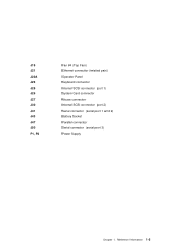
J19 J21 J22A J23 J25 J26 J27 J30 J41 J43 J47 J50 P1, P2 Fan #4 (Top Fan) Ethernet connector (twisted pair) Operator Panel Keyboard connector Internal SCSI connector (port 1) System Card connector Mouse connector Internal SCSI connector (port 2) Serial connector (serial port 1 and 2) Battery Socket Parallel connector Serial connector (serial port 3) Power Supply Chapter 1. Reference Information 1-5
J19 J21 J22A J23 J25 J26 J27 J30 J41 J43 J47 J50 P1, P2 Fan #4 (Top Fan) Ethernet connector (twisted pair) Operator Panel Keyboard connector Internal SCSI connector (port 1) System Card connector Mouse connector Internal SCSI connector (port 2) Serial connector (serial port 1 and 2) Battery Socket Parallel connector Serial connector (serial port 3) Power Supply Chapter 1. Reference Information 1-5

Service Guide
Page 23
Reference Information 1-7 Operator Panel Chapter 1.
Reference Information 1-7 Operator Panel Chapter 1.
Service Guide
Page 25
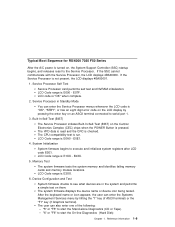
LCD Code range is checked. Built-In-Self-Test (BIST) The Service Processor initiates Built-In-Self-Test (BIST) on , the System Support Controller (SSC) startup begins, and releases reset to serial port 1. 3. The VPD data is read and the CRC is E000 - The CPU compatibility test is not present, the LCD displays 4BA00001. 1. System Initialization System firmware begins to start the Stand-alone Diagnostics (CD or Tape). - The user can enter the Service Processor menus whenever the LCD code is "OK", "STBY", or has an eight digit error code on the LCD display by hitting the "1" key (if...
LCD Code range is checked. Built-In-Self-Test (BIST) The Service Processor initiates Built-In-Self-Test (BIST) on , the System Support Controller (SSC) startup begins, and releases reset to serial port 1. 3. The VPD data is read and the CRC is E000 - The CPU compatibility test is not present, the LCD displays 4BA00001. 1. System Initialization System firmware begins to start the Stand-alone Diagnostics (CD or Tape). - The user can enter the Service Processor menus whenever the LCD code is "OK", "STBY", or has an eight digit error code on the LCD display by hitting the "1" key (if...
Service Guide
Page 26
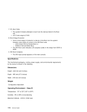
The AIX Boot code indicates LCD progress codes in the range from the devices listed in the Boot List. Boot Image Execution Once a boot image is located on the main console. AIX Boot Complete The AIX login prompt appears on a device in the following: Dimensions Height - 620 mm (24.3 inches) Depth - 695 mm (27.3 inches) Width - 245 mm (9.6 inches) Weight Configuration dependent Operating Environment - Specifications The mechanical packaging, cooling, power supply, and environmental requirements for Service Mode Boot. E15B for the server is E1XX. 8. 7. LCD Code E105 for ...
The AIX Boot code indicates LCD progress codes in the range from the devices listed in the Boot List. Boot Image Execution Once a boot image is located on the main console. AIX Boot Complete The AIX login prompt appears on a device in the following: Dimensions Height - 620 mm (24.3 inches) Depth - 695 mm (27.3 inches) Width - 245 mm (9.6 inches) Weight Configuration dependent Operating Environment - Specifications The mechanical packaging, cooling, power supply, and environmental requirements for Service Mode Boot. E15B for the server is E1XX. 8. 7. LCD Code E105 for ...

Service Guide
Page 27
Reference Information 1-11 Power Source Loading Typical EMC Configuration - 0.28 kVA Maximum - 0.65 kVA Power Requirements Typical - 154 watts Maximum - 450 watts Power Factor 0.8 - 0.98 Operating Voltage 100 to 127V ac; 50 to 60 Hz 200 to 240V ac; 50 to 60 Hz Heat Output (Maximum) Typical - 800 BTU/hr Maximum - 2300 BTU/hr Acoustics 6.0 Bels operating 5.5 Bels idle Chapter 1.
Reference Information 1-11 Power Source Loading Typical EMC Configuration - 0.28 kVA Maximum - 0.65 kVA Power Requirements Typical - 154 watts Maximum - 450 watts Power Factor 0.8 - 0.98 Operating Voltage 100 to 127V ac; 50 to 60 Hz 200 to 240V ac; 50 to 60 Hz Heat Output (Maximum) Typical - 800 BTU/hr Maximum - 2300 BTU/hr Acoustics 6.0 Bels operating 5.5 Bels idle Chapter 1.
Service Guide
Page 28
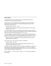
Power cables used . These power cords consist of the following: Electrical cables, Type HD21. Power cables used in which the equipment will be installed and should have the appropriate safety approvals for the specific countries where they are used in length and a parallel blade, grounding type attachment plug rated at 15 A, 125 V." Attachment plugs approved by the Canadian Standards Association (CSA). The cable set should be marked HAR'." Appliance couplers complying with National Electrical Manufacturers Association (NEMA) 5-15P. "For units set at 15 A, 250 V." That is ...
Power cables used . These power cords consist of the following: Electrical cables, Type HD21. Power cables used in which the equipment will be installed and should have the appropriate safety approvals for the specific countries where they are used in length and a parallel blade, grounding type attachment plug rated at 15 A, 125 V." Attachment plugs approved by the Canadian Standards Association (CSA). The cable set should be marked HAR'." Appliance couplers complying with National Electrical Manufacturers Association (NEMA) 5-15P. "For units set at 15 A, 250 V." That is ...
