User Guide
Page 5
... password (clearing CMOS 56 Using Security Profile by Device 57 Other settings in the IBM Setup Utility program . . 57 The startup sequence 57 Changing the startup sequence 57 Appendix A. Installing internal options - desktop model 29 Removing the cover 29 Locating components 30 Identifying parts on the system board . . . . . 18 Installing memory 19 Installing DIMMs 19 Installing adapters 20 Installing internal drives 23 Drive specifications 23 Installing a drive 24 Installing a Rope Clip 25 Replacing the cover and connecting the cables. . . 26 Chapter 4. microtower model...
... password (clearing CMOS 56 Using Security Profile by Device 57 Other settings in the IBM Setup Utility program . . 57 The startup sequence 57 Changing the startup sequence 57 Appendix A. Installing internal options - desktop model 29 Removing the cover 29 Locating components 30 Identifying parts on the system board . . . . . 18 Installing memory 19 Installing DIMMs 19 Installing adapters 20 Installing internal drives 23 Drive specifications 23 Installing a drive 24 Installing a Rope Clip 25 Replacing the cover and connecting the cables. . . 26 Chapter 4. microtower model...
User Guide
Page 9
... type) during an electrical storm. There may be a remote risk of the leak. CD-ROM drives and DVD-ROM drives are laser products. CD-ROM drives and DVD-ROM drives are also sold separately as options. CAUTION: Use of controls or adjustments or performance of Federal Regulations (DHHS 21 CFR) Subchapter J for wet locations. v Never install telephone jacks in hazardous radiation exposure. Elsewhere, these drives are no serviceable parts inside the...
... type) during an electrical storm. There may be a remote risk of the leak. CD-ROM drives and DVD-ROM drives are laser products. CD-ROM drives and DVD-ROM drives are also sold separately as options. CAUTION: Use of controls or adjustments or performance of Federal Regulations (DHHS 21 CFR) Subchapter J for wet locations. v Never install telephone jacks in hazardous radiation exposure. Elsewhere, these drives are no serviceable parts inside the...
User Guide
Page 11
... you to the computer specifications and the options that are available for installing external options and peripheral devices. small desktop model" provides instructions for removing the cover and installing hard disk drives, memory, and adapters in your computer and instructions for your system programs. v "Appendix C. v "Chapter 5. Installing internal options - Notices and trademarks" contains notice and trademark information. © Copyright IBM Corp. 2001 ix v "Chapter 3. Changing the battery" provides instructions to help you update your computer. System...
... you to the computer specifications and the options that are available for installing external options and peripheral devices. small desktop model" provides instructions for removing the cover and installing hard disk drives, memory, and adapters in your computer and instructions for your system programs. v "Appendix C. v "Chapter 5. Installing internal options - Notices and trademarks" contains notice and trademark information. © Copyright IBM Corp. 2001 ix v "Chapter 3. Changing the battery" provides instructions to help you update your computer. System...

User Guide
Page 15
... flash memory for system programs Internal drives v 3.5-inch, 1.44 MB diskette drive v Internal hard disk drive v EIDE CD drive or DVD drive Video subsystem AGP video adapter slot on the system board Audio subsystem 16-bit integrated Sound Blaster Pro compatible audio subsystem Connectivity v 10/100 Mbps integrated Intel ethernet controller that supports the Wake on LAN® feature v 56k V.90 data/fax PCI modem (some models) System management features (varies by model type) v Remote Program Load (RPL) and Dynamic Host Configuration Protocol (DHCP) v Wake...
... flash memory for system programs Internal drives v 3.5-inch, 1.44 MB diskette drive v Internal hard disk drive v EIDE CD drive or DVD drive Video subsystem AGP video adapter slot on the system board Audio subsystem 16-bit integrated Sound Blaster Pro compatible audio subsystem Connectivity v 10/100 Mbps integrated Intel ethernet controller that supports the Wake on LAN® feature v 56k V.90 data/fax PCI modem (some models) System management features (varies by model type) v Remote Program Load (RPL) and Dynamic Host Configuration Protocol (DHCP) v Wake...
User Guide
Page 20
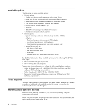
...://www.ibm.com/pc/us/options/ v http://www.pc.ibm.com/support/ You can seriously damage computer components and options. Parallel port devices, such as external modems and digital cameras - Serial port devices, such as printers and external drives - Security device, such as : - Adapters - Accelerated graphics port (AGP) adapters - Small desktop models support low profile adapters only - Internal drives, such as a Rope Clip - Hard disk - Tools required To install some available options: v External options - See the instructions that come with the option.
...://www.ibm.com/pc/us/options/ v http://www.pc.ibm.com/support/ You can seriously damage computer components and options. Parallel port devices, such as external modems and digital cameras - Serial port devices, such as printers and external drives - Security device, such as : - Adapters - Accelerated graphics port (AGP) adapters - Small desktop models support low profile adapters only - Internal drives, such as a Rope Clip - Hard disk - Tools required To install some available options: v External options - See the instructions that come with the option.

User Guide
Page 25
... 2. Installing external options 13 See page 16 for connector descriptions. 1 Mouse connector 2 Parallel connector 3 Audio line in connector 4 Power connector 5 PCI slots 6 AGP slot 7 Audio line out connector 8 Microphone connector 9 Ethernet connector 10 Serial connector 11 Serial connector 12 USB connectors 13 Keyboard connector Note: Some connectors on your computer The following illustration shows the location of the connectors on the rear of the computer are color-coded to help you to determine where to connect the cables on the rear of the small desktop model computer...
... 2. Installing external options 13 See page 16 for connector descriptions. 1 Mouse connector 2 Parallel connector 3 Audio line in connector 4 Power connector 5 PCI slots 6 AGP slot 7 Audio line out connector 8 Microphone connector 9 Ethernet connector 10 Serial connector 11 Serial connector 12 USB connectors 13 Keyboard connector Note: Some connectors on your computer The following illustration shows the location of the connectors on the rear of the computer are color-coded to help you to determine where to connect the cables on the rear of the small desktop model computer...

User Guide
Page 27
The following illustration shows the location of the connectors on the back of the computer are color-coded to help you to determine where to connect the cables on the rear of the microtower model computer. Installing external options 15 Chapter 2. See page 16 for connector descriptions. 1 Mouse connector 2 Keyboard connector 3 USB connectors 4 Serial connector 5 Parallel connector 6 Serial connector 7 Ethernet connector 8 Microphone connector 9 Audio line out connector 10 Audio line in connector 11 AGP slot 12 PCI slots 13 Power connector Note: Some connectors on your computer.
The following illustration shows the location of the connectors on the back of the computer are color-coded to help you to determine where to connect the cables on the rear of the microtower model computer. Installing external options 15 Chapter 2. See page 16 for connector descriptions. 1 Mouse connector 2 Keyboard connector 3 USB connectors 4 Serial connector 5 Parallel connector 6 Serial connector 7 Ethernet connector 8 Microphone connector 9 Audio line out connector 10 Audio line in connector 11 AGP slot 12 PCI slots 13 Power connector Note: Some connectors on your computer.

User Guide
Page 28
... requires a Universal Serial Bus (USB) connection, such as a USB scanner or USB printer. Audio line out connector Used to send audio signals from an external audio device, such as powered stereo speakers (speakers with the device driver files. 16 User Guide Obtaining device drivers You can obtain device drivers for a Local Area Network (LAN). If you have more than four USB devices, you can use a category 5 Ethernet cable. Note: To operate the computer within FCC Class B limits, use to attach a mouse, trackball, or...
... requires a Universal Serial Bus (USB) connection, such as a USB scanner or USB printer. Audio line out connector Used to send audio signals from an external audio device, such as powered stereo speakers (speakers with the device driver files. 16 User Guide Obtaining device drivers You can obtain device drivers for a Local Area Network (LAN). If you have more than four USB devices, you can use a category 5 Ethernet cable. Note: To operate the computer within FCC Class B limits, use to attach a mouse, trackball, or...

User Guide
Page 31
... 5 Diskette drive connector 6 Primary IDE connector 7 Secondary IDE connector 8 Clear CMOS/Recovery jumper 9 Battery 10 SCSI LED connector 11 PCI slots 12 Front panel audio connector 13 CD-ROM audio connector 14 AGP slot 15 12V Power connector Installing memory Your computer has three connectors for the location of parts on page 17. Installing internal options - See "Removing the cover" on the system board. 1 Microprocessor 2 DIMM connectors (1, 2, 3 left to right). See the following rules apply: v Fill each system memory connector sequentially, starting at DIMM 1 v Use...
... 5 Diskette drive connector 6 Primary IDE connector 7 Secondary IDE connector 8 Clear CMOS/Recovery jumper 9 Battery 10 SCSI LED connector 11 PCI slots 12 Front panel audio connector 13 CD-ROM audio connector 14 AGP slot 15 12V Power connector Installing memory Your computer has three connectors for the location of parts on page 17. Installing internal options - See "Removing the cover" on the system board. 1 Microprocessor 2 DIMM connectors (1, 2, 3 left to right). See the following rules apply: v Fill each system memory connector sequentially, starting at DIMM 1 v Use...

User Guide
Page 35
... diskette drive in bay 1 v A CD drive or DVD drive in bay 2 v A 3.5-inch hard disk drive in the accessible bay: bay 2. Chapter 3. You can add or replace drives to your computer to increase storage capacity and to enable your computer uses to the installed drive. Within this book, the bays are devices that your computer to read and store data. Installing internal drives This section provides information and instructions for installing and removing internal drives. Internal drives...
... diskette drive in bay 1 v A CD drive or DVD drive in bay 2 v A 3.5-inch hard disk drive in the accessible bay: bay 2. Chapter 3. You can add or replace drives to your computer to increase storage capacity and to enable your computer uses to the installed drive. Within this book, the bays are devices that your computer to read and store data. Installing internal drives This section provides information and instructions for installing and removing internal drives. Internal drives...

User Guide
Page 36
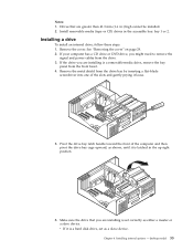
... the master device. Each integrated drive electronics (IDE) drive requires two cables; Installing a drive To install a CD drive or DVD drive in the up position. 6. Refer to the documentation that connects to the power supply, and a signal cable that comes with your CD drive or DVD drive for master/slave jumper information. 5. a four-wire power cable that connects to the system board. Align the screw holes and insert the two screws. 24 User Guide 7. Remove the...
... the master device. Each integrated drive electronics (IDE) drive requires two cables; Installing a drive To install a CD drive or DVD drive in the up position. 6. Refer to the documentation that connects to the power supply, and a signal cable that comes with your CD drive or DVD drive for master/slave jumper information. 5. a four-wire power cable that connects to the system board. Align the screw holes and insert the two screws. 24 User Guide 7. Remove the...

User Guide
Page 43
... panel connector 4 Power connector 5 Diskette drive connector 6 Primary IDE connector 7 Secondary IDE connector 8 Clear CMOS/Recovery jumper 9 Battery 10 SCSI LED connector 11 PCI slots 12 Front panel audio connector 13 CD-ROM audio connector 14 AGP slot 15 12V Power connector Installing memory Your computer has three connectors for installing dual in any combination v DIMM heights of system memory. You might have to remove an adapter to gain access to the DIMM slots. desktop model 31 Remove the cover. See "Installing adapters" on page 29. 2. Chapter 4. Installing internal options...
... panel connector 4 Power connector 5 Diskette drive connector 6 Primary IDE connector 7 Secondary IDE connector 8 Clear CMOS/Recovery jumper 9 Battery 10 SCSI LED connector 11 PCI slots 12 Front panel audio connector 13 CD-ROM audio connector 14 AGP slot 15 12V Power connector Installing memory Your computer has three connectors for installing dual in any combination v DIMM heights of system memory. You might have to remove an adapter to gain access to the DIMM slots. desktop model 31 Remove the cover. See "Installing adapters" on page 29. 2. Chapter 4. Installing internal options...
User Guide
Page 47
... the accessible bay: bay 1 or 2. Installing internal options - Drives that you are installing is a removable-media drive, remove the bay panel from the drive. 3. Install removable media (tape or CD) drives in the up right position. 6. If the drive you are installing is set as either a master or a slave device. desktop model 35 Notes: 1. If your computer has a CD drive or DVD drive, you might need to remove the signal and power cables from the front bezel. 4. See "Removing the cover...
... the accessible bay: bay 1 or 2. Installing internal options - Drives that you are installing is a removable-media drive, remove the bay panel from the drive. 3. Install removable media (tape or CD) drives in the up right position. 6. If the drive you are installing is set as either a master or a slave device. desktop model 35 Notes: 1. If your computer has a CD drive or DVD drive, you might need to remove the signal and power cables from the front bezel. 4. See "Removing the cover...

User Guide
Page 56
... MB, 128 MB, 256 MB, or 512 MB DIMMs in -line memory modules (DIMMs) that provide up to a maximum of 1.5 GB of 38.1 mm (1.5 inches) To install a DIMM: 1. Remove the cover. See "Removing the cover" on page 45. 44 User Guide You might have to remove an adapter to gain access to right) 3 Front panel connector 4 Power connector 5 Diskette drive connector 6 Primary IDE connector 7 Secondary IDE connector 8 Clear CMOS/Recovery jumper 9 Battery 10 SCSI LED connector 11 PCI slots 12 Front panel audio connector 13 CD-ROM audio connector...
... MB, 128 MB, 256 MB, or 512 MB DIMMs in -line memory modules (DIMMs) that provide up to a maximum of 1.5 GB of 38.1 mm (1.5 inches) To install a DIMM: 1. Remove the cover. See "Removing the cover" on page 45. 44 User Guide You might have to remove an adapter to gain access to right) 3 Front panel connector 4 Power connector 5 Diskette drive connector 6 Primary IDE connector 7 Secondary IDE connector 8 Clear CMOS/Recovery jumper 9 Battery 10 SCSI LED connector 11 PCI slots 12 Front panel audio connector 13 CD-ROM audio connector...
User Guide
Page 68
... board. If you type the wrong password three times, you must use your administrator password. Z, a-z, and 0-9). 1. Read the information displayed at the right side of up to all attached devices. 2. Locate the Clear CMOS/Recovery jumper on page 43 (microtower model). 5. If necessary, refer to Installing adapters to remove any configuration settings, you might not apply to seven characters (A- See "Replacing the cover and connecting the cables" on page 26 (small desktop model), "Replacing the cover...
... board. If you type the wrong password three times, you must use your administrator password. Z, a-z, and 0-9). 1. Read the information displayed at the right side of up to all attached devices. 2. Locate the Clear CMOS/Recovery jumper on page 43 (microtower model). 5. If necessary, refer to Installing adapters to remove any configuration settings, you might not apply to seven characters (A- See "Replacing the cover and connecting the cables" on page 26 (small desktop model), "Replacing the cover...
User Guide
Page 69
... treated as hard disk drives or the CD-ROM drive) are write-protected. From the IBM Setup Utility program menu, select Security. 3. When this feature is set to the IDE controller (such as if they are disabled and will be accessed. No permanent changes are displayed on automatically, such as over a network or by Device, do the following : 1. Using the IBM Setup Utility program 57 Replace the cover and connect the power cord. Using Security Profile...
... treated as hard disk drives or the CD-ROM drive) are write-protected. From the IBM Setup Utility program menu, select Security. 3. When this feature is set to the IDE controller (such as if they are disabled and will be accessed. No permanent changes are displayed on automatically, such as over a network or by Device, do the following : 1. Using the IBM Setup Utility program 57 Replace the cover and connect the power cord. Using Security Profile...
User Guide
Page 71
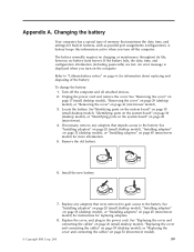
... configuration information (including passwords) are lost. An error message is displayed when you turn on page 45 (microtower model) for replacing adapters. 8. Replace any adapters that impede access to the battery. See "Removing the cover" on page 17 (small desktop model), "Removing the cover" on page 29 (desktop model), or "Removing the cover" on page 52 (microtower model). © Copyright IBM Corp. 2001 59 Changing the battery Your computer has a special type of memory that were removed to gain access...
... configuration information (including passwords) are lost. An error message is displayed when you turn on page 45 (microtower model) for replacing adapters. 8. Replace any adapters that impede access to the battery. See "Removing the cover" on page 17 (small desktop model), "Removing the cover" on page 29 (desktop model), or "Removing the cover" on page 52 (microtower model). © Copyright IBM Corp. 2001 59 Changing the battery Your computer has a special type of memory that were removed to gain access...

User Guide
Page 73
... any adapters that impede access to as printers, monitors, and external drives. 2. You can use the IBM Setup Utility program to view and change the configuration and setup of tests and procedures that is on already, you turn it is built into your computer. Instructions for using a flash update diskette. Recovering from electrical outlets, and remove the cover. Locate the Clear CMOS/Recovery jumper on self-test (POST), the basic input/output system (BIOS) code, and the IBM Setup Utility program. Updating...
... any adapters that impede access to as printers, monitors, and external drives. 2. You can use the IBM Setup Utility program to view and change the configuration and setup of tests and procedures that is on already, you turn it is built into your computer. Instructions for using a flash update diskette. Recovering from electrical outlets, and remove the cover. Locate the Clear CMOS/Recovery jumper on self-test (POST), the basic input/output system (BIOS) code, and the IBM Setup Utility program. Updating...

User Guide
Page 83
... replacing desktop model 38 microtower model 52 small desktop model 26 D device, drivers 16 DIMMs, installing 19, 31, 44 DMA channel assignments 67 DMA I/O address map 65 drives bays 4, 23, 33, 47 CD 8, 34, 47 diskette 8 DVD 8, 34, 47 hard disk 8, 34, 47 installing 23, 24, 33, 35, 47, 48 internal 3, 8, 47, 48 removable media 8, 34, 47 specifications 23, 34, 47 tape 34 © Copyright IBM Corp. 2001 E environment, operating 5, 6, 7 Ethernet connector...
... replacing desktop model 38 microtower model 52 small desktop model 26 D device, drivers 16 DIMMs, installing 19, 31, 44 DMA channel assignments 67 DMA I/O address map 65 drives bays 4, 23, 33, 47 CD 8, 34, 47 diskette 8 DVD 8, 34, 47 hard disk 8, 34, 47 installing 23, 24, 33, 35, 47, 48 internal 3, 8, 47, 48 removable media 8, 34, 47 specifications 23, 34, 47 tape 34 © Copyright IBM Corp. 2001 E environment, operating 5, 6, 7 Ethernet connector...
User Guide
Page 84
... small desktop model 17 internal 8, 17, 29, 41 P parallel connector 13, 14, 15, 16 password erasing 56 lost or forgotten 56 setting, changing, deleting 56 power Advanced Configuration and Power Interface (ACPI) support 4 Advanced Power Management support 4 R recovering from a POST/BIOS update failure 61 removing the cover desktop model 29 microtower model 41 small desktop model 17 replacing the cover desktop model 38 microtower model 52 small desktop model 26 S security features 4 Rope Clip 25, 37, 51 security profile by device 57 serial connectors...
... small desktop model 17 internal 8, 17, 29, 41 P parallel connector 13, 14, 15, 16 password erasing 56 lost or forgotten 56 setting, changing, deleting 56 power Advanced Configuration and Power Interface (ACPI) support 4 Advanced Power Management support 4 R recovering from a POST/BIOS update failure 61 removing the cover desktop model 29 microtower model 41 small desktop model 17 replacing the cover desktop model 38 microtower model 52 small desktop model 26 S security features 4 Rope Clip 25, 37, 51 security profile by device 57 serial connectors...


