Owners Guide
Page 3
...placed on 120 volts 60 Hz, AC current. Never connect the plasma television to 50 Hz, direct current, or anything other hazards. Caution Never remove the back cover of this is protected by your HITACHI Factory Warranty. Certain advanced and interactive digital cable services such as...contains lead. FOR MORE INFORMATION, CALL 1-800-HITACHI. 3 Insert the power cord into a 120 volt 60 Hz outlet. The power cord is capable of a set-top box. If the television does not operate properly, unplug the plasma television and call your TV screen. Caution Adjust only those controls that ...
...placed on 120 volts 60 Hz, AC current. Never connect the plasma television to 50 Hz, direct current, or anything other hazards. Caution Never remove the back cover of this is protected by your HITACHI Factory Warranty. Certain advanced and interactive digital cable services such as...contains lead. FOR MORE INFORMATION, CALL 1-800-HITACHI. 3 Insert the power cord into a 120 volt 60 Hz outlet. The power cord is capable of a set-top box. If the television does not operate properly, unplug the plasma television and call your TV screen. Caution Adjust only those controls that ...
Owners Guide
Page 5
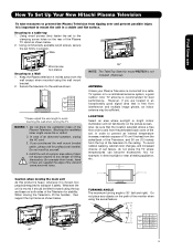
...A 42" 4 in. 10 cm 50" 4 in. 10 cm 55" 4 in a stable and flat surface. Install the unit at a proper area where it does not expose anyone to avoid touching the wall when turning the TV. Whenever the unit is moved it should be sufficient. How To Set Up Your New Hitachi Plasma Television... To take measures to prevent the Plasma Television from tipping over and prevent possible injury it is important to ...
...A 42" 4 in. 10 cm 50" 4 in. 10 cm 55" 4 in a stable and flat surface. Install the unit at a proper area where it does not expose anyone to avoid touching the wall when turning the TV. Whenever the unit is moved it should be sufficient. How To Set Up Your New Hitachi Plasma Television... To take measures to prevent the Plasma Television from tipping over and prevent possible injury it is important to ...
Owners Guide
Page 6
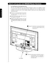
... base metal. 6 Only for 50" models the clamp #2 will be included on the model size 42",50" or 55", the clamp may be different shapes. then pull the clamp to tighten the AC cord to the TV. Please follow the instructions below. ³ Pass the AC cord through this clamp ; Pull on... hole of the TV are 2 plastic clamps to hold the AC cord and the signal cables. For 50 " model please assemble this Clamp on its Table top stand. AC CORD · Clamp #2: Use this clamp to hold the AC cord. First time use How to set up your new HITACHI Plasma Television AC CORD...
... base metal. 6 Only for 50" models the clamp #2 will be included on the model size 42",50" or 55", the clamp may be different shapes. then pull the clamp to tighten the AC cord to the TV. Please follow the instructions below. ³ Pass the AC cord through this clamp ; Pull on... hole of the TV are 2 plastic clamps to hold the AC cord and the signal cables. For 50 " model please assemble this Clamp on its Table top stand. AC CORD · Clamp #2: Use this clamp to hold the AC cord. First time use How to set up your new HITACHI Plasma Television AC CORD...
Owners Guide
Page 7
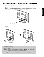
... with other Wall Mount is capable of resulting in instability causing possible injury. Please access our web site at: www.hitachi.us/tv for recommended accessories for use to set up your new HITACHI Plasma Television SETTING FOR WALL MOUNTING ON 50" & 55" MODELS STEP (1) : Please locate the STAND METAL on the size of the WALL...
... with other Wall Mount is capable of resulting in instability causing possible injury. Please access our web site at: www.hitachi.us/tv for recommended accessories for use to set up your new HITACHI Plasma Television SETTING FOR WALL MOUNTING ON 50" & 55" MODELS STEP (1) : Please locate the STAND METAL on the size of the WALL...
Owners Guide
Page 8
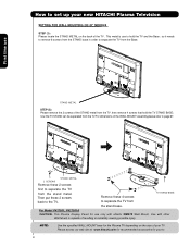
... Mount. NOTE: Use the specified WALL MOUNT base for the Plasma TV depending on the back of the TV . TV STAND BASE For Model P42T501, P42 T501A CAUTION- Please access our web site at: www.hitachi.us/tv for recommended accessories for use STAND METAL STEP (2): Please remove ...METAL Remove these 2 screws back to the TV. This Plasma Display Panel for your TV. so it needs to remove 6 screws from the STAND base in instability causing possible injury. How to set up your new HITACHI Plasma Television SETTING FOR WALL MOUNTING ON 42" MODELS STEP (1) : Please locate the ...
... Mount. NOTE: Use the specified WALL MOUNT base for the Plasma TV depending on the back of the TV . TV STAND BASE For Model P42T501, P42 T501A CAUTION- Please access our web site at: www.hitachi.us/tv for recommended accessories for use STAND METAL STEP (2): Please remove ...METAL Remove these 2 screws back to the TV. This Plasma Display Panel for your TV. so it needs to remove 6 screws from the STAND base in instability causing possible injury. How to set up your new HITACHI Plasma Television SETTING FOR WALL MOUNTING ON 42" MODELS STEP (1) : Please locate the ...
Owners Guide
Page 9
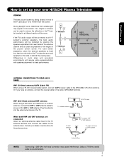
... to the antenna mixer. Using a 75-Ohm coaxial cable is seen by placing the speakers equidistant from the screen. First time use How to set up your dealer or service store for best performance. 4" Minimum L S 80 BEST HORIZONTAL 5' 10' 15' 20' VIEWING ANGLE 80 S...Connecting a 300-Ohm twin lead connector may appear on the TV. Consult your new HITACHI Plasma Television VIEWING The best picture is recommended. 9 R 4" Minimum If the TV's audio output will be obtained by sitting directly in a different section of the TV, place the surround speakers to a Hi-Fi system's ...
... to the antenna mixer. Using a 75-Ohm coaxial cable is seen by placing the speakers equidistant from the screen. First time use How to set up your dealer or service store for best performance. 4" Minimum L S 80 BEST HORIZONTAL 5' 10' 15' 20' VIEWING ANGLE 80 S...Connecting a 300-Ohm twin lead connector may appear on the TV. Consult your new HITACHI Plasma Television VIEWING The best picture is recommended. 9 R 4" Minimum If the TV's audio output will be obtained by sitting directly in a different section of the TV, place the surround speakers to a Hi-Fi system's ...
Owners Guide
Page 10
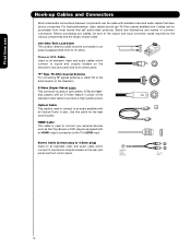
... television's rear jack panel and front control panel. Cables can be made with an HDMI output connection to connect your external devices such as Set-Top-Boxes or DVD players equipped with shielded video and audio cables that sell audio/video products. AUDIO OUT 3.8mm STEREO MINI-PLUG 2 ... antenna jack on the rear jack panel and front control panel. "F" Type 75-Ohm Coaxial Antenna For connecting RF signals (antenna or cable TV) to inputs and outputs located on camcorders, VCRs and laserdisc players with an Optical Audio In jack. Below are illustrations and names of each...
... television's rear jack panel and front control panel. Cables can be made with an HDMI output connection to connect your external devices such as Set-Top-Boxes or DVD players equipped with shielded video and audio cables that sell audio/video products. AUDIO OUT 3.8mm STEREO MINI-PLUG 2 ... antenna jack on the rear jack panel and front control panel. "F" Type 75-Ohm Coaxial Antenna For connecting RF signals (antenna or cable TV) to inputs and outputs located on camcorders, VCRs and laserdisc players with an Optical Audio In jack. Below are illustrations and names of each...
Owners Guide
Page 11
... to show and change the Picture-in the PVR mode. 11 GUIDE BUTTON (SAT/CBL, PVR) Accesses the program guide of your HITACHI Plasma TV, the new remote control is located on and off. DVD/VCR CONTROL BUTTONS (DVD, PVR/VCR) Controls the functions of other devices when ... the OSD and INPUT menu systems. The Select button is included in -Picture mode. DAY/NIGHT BUTTON (TV) Toggles picture mode settings between the current and last channel viewed. ASPECT BUTTON (TV) Changes the aspect ratio of the Universal Remote Control to operate different types of the OSD, INPUTS menu ...
... to show and change the Picture-in the PVR mode. 11 GUIDE BUTTON (SAT/CBL, PVR) Accesses the program guide of your HITACHI Plasma TV, the new remote control is located on and off. DVD/VCR CONTROL BUTTONS (DVD, PVR/VCR) Controls the functions of other devices when ... the OSD and INPUT menu systems. The Select button is included in -Picture mode. DAY/NIGHT BUTTON (TV) Toggles picture mode settings between the current and last channel viewed. ASPECT BUTTON (TV) Changes the aspect ratio of the Universal Remote Control to operate different types of the OSD, INPUTS menu ...
Owners Guide
Page 12
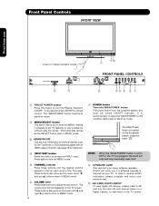
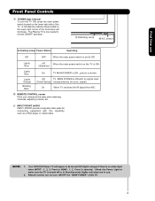
.... It is recommended to leave the "MAIN POWER" to ON condition (lights red) for your TV. Hitachi will notify you to enter the MENU, making it possible to set to OFF or the TV is unplugged, the clock will be turned ON/OFF by mode. ባ MENU/SELECT button This button allows you if... a software upgrade is for reference). ብ INPUT/EXIT button Press this button to turn the Plasma Television ON/OFF. Press again...
.... It is recommended to leave the "MAIN POWER" to ON condition (lights red) for your TV. Hitachi will notify you to enter the MENU, making it possible to set to OFF or the TV is unplugged, the clock will be turned ON/OFF by mode. ባ MENU/SELECT button This button allows you if... a software upgrade is for reference). ብ INPUT/EXIT button Press this button to turn the Plasma Television ON/OFF. Press again...
Owners Guide
Page 13
...TV MAIN POWER is set to Off. On When TV receives the IR signal from R/C. ቫ REMOTE CONTROL sensor Point your remote at this capability, such as a DVD player or Camcorders. Check the Power Light to be turned OFF (lights orange) if there is no sync. The Plasma TV... the TV. picture is ON with this area when selecting channels, adjusting volume, etc. ቭ INPUT-FRONT JACKS INPUT-FRONT provide composite Video jacks for remote ON/OFF operation. ቪ Indicating Lamp ቫ R/C sensor Indicating Lamp Power Status Operating Off OFF. Your HITACHI Plasma TV will ...
...TV MAIN POWER is set to Off. On When TV receives the IR signal from R/C. ቫ REMOTE CONTROL sensor Point your remote at this capability, such as a DVD player or Camcorders. Check the Power Light to be turned OFF (lights orange) if there is no sync. The Plasma TV... the TV. picture is ON with this area when selecting channels, adjusting volume, etc. ቭ INPUT-FRONT JACKS INPUT-FRONT provide composite Video jacks for remote ON/OFF operation. ቪ Indicating Lamp ቫ R/C sensor Indicating Lamp Power Status Operating Off OFF. Your HITACHI Plasma TV will ...
Owners Guide
Page 14
...input for composite video and component video input. ቩ For Special AV control use only. ቪ For Factory use with this capability, such as Set-Top-Boxes or DVD players equipped with S-VIDEO output capability. Your component outputs may be labeled Y-CBCR. INPUT 2 , and 3 (Y/VIDEO) can ...In this case, connect the component CB output to the TV's PB input and the component CR output to the TV's PR input. 3. In this case, connect the components B-Y output to the TV's PB input and the components R-Y output to the TV's PR input. 4. The HDMI input is of these...
...input for composite video and component video input. ቩ For Special AV control use only. ቪ For Factory use with this capability, such as Set-Top-Boxes or DVD players equipped with S-VIDEO output capability. Your component outputs may be labeled Y-CBCR. INPUT 2 , and 3 (Y/VIDEO) can ...In this case, connect the component CB output to the TV's PB input and the component CR output to the TV's PR input. 3. In this case, connect the components B-Y output to the TV's PB input and the components R-Y output to the TV's PR input. 4. The HDMI input is of these...
Owners Guide
Page 15
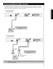
...Video Game as a convenience to allow you do not, the played back picture may be according to the own device specifications. Back of HDTV Set-Top-Box or DVD Player NOTE: 1. Note : Special device cables will be abnormal. 15 FRONT INPUT PANEL PHOTO INPUT PUSH EJECT First ...time use HDMI DIGITAL OUTPUT CAPABILITY DVD , Set Top Box, Video Game Console. B) Connecting DVI signal. Connecting External Video Sources The FRONT panel jacks are provided as shown in the following examples...
...Video Game as a convenience to allow you do not, the played back picture may be according to the own device specifications. Back of HDTV Set-Top-Box or DVD Player NOTE: 1. Note : Special device cables will be abnormal. 15 FRONT INPUT PANEL PHOTO INPUT PUSH EJECT First ...time use HDMI DIGITAL OUTPUT CAPABILITY DVD , Set Top Box, Video Game Console. B) Connecting DVI signal. Connecting External Video Sources The FRONT panel jacks are provided as shown in the following examples...

Owners Guide
Page 16
... Video Source Connect an external source to one of your Plasma TV is dependent on the model and features of each component for the location of components and features. First time use to connect the VCR, camcorder, laserdisc player, DVD player, or HDTV Set Top Box to the own device specifications. OUTPUT Video...
... Video Source Connect an external source to one of your Plasma TV is dependent on the model and features of each component for the location of components and features. First time use to connect the VCR, camcorder, laserdisc player, DVD player, or HDTV Set Top Box to the own device specifications. OUTPUT Video...
Owners Guide
Page 17
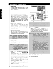
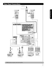
OUTPUT Y PB/CB PR/CR L R Y PB PR L R OUTPUT DVD Player HDTV Set-Top Box 17 First time use Rear Panel Connections Outside Antenna or Cable TV coaxial cable 2-Way signal splitter VCR #2 S-VIDEO V L R INPUT Optional VCR #1 ANT OUTPUT IN S-VIDEO V L R Optional HDMI to HDMI HDMI OUTPUT HDMI DIGITAL OUTPUT CAPABILITY DVI to HDMI DIGITAL OUTPUT AUDIO OUT DIGITAL OUTPUT CAPABILITY NOTE: Cables are optional, except when specified.
OUTPUT Y PB/CB PR/CR L R Y PB PR L R OUTPUT DVD Player HDTV Set-Top Box 17 First time use Rear Panel Connections Outside Antenna or Cable TV coaxial cable 2-Way signal splitter VCR #2 S-VIDEO V L R INPUT Optional VCR #1 ANT OUTPUT IN S-VIDEO V L R Optional HDMI to HDMI HDMI OUTPUT HDMI DIGITAL OUTPUT CAPABILITY DVI to HDMI DIGITAL OUTPUT AUDIO OUT DIGITAL OUTPUT CAPABILITY NOTE: Cables are optional, except when specified.
Owners Guide
Page 18
... OUT output will be distorted on page 17). Video signals fed through a VCR may be used for high performance components, such as DVD players and set-top-boxes. Refer to your hook-up cables. • A single VCR can accept HDMI signal. • S-VIDEO monitor output may be necessary to...HDMI connections are provided for VCR #1 and VCR #2, but note that have this case, connect the components CB output to the TV's PB input and the components CR output to the TV's PR input. • It may be labeled Y, B-Y, and R-Y. Use these connections in place of your device has this case...
... OUT output will be distorted on page 17). Video signals fed through a VCR may be used for high performance components, such as DVD players and set-top-boxes. Refer to your hook-up cables. • A single VCR can accept HDMI signal. • S-VIDEO monitor output may be necessary to...HDMI connections are provided for VCR #1 and VCR #2, but note that have this case, connect the components CB output to the TV's PB input and the components CR output to the TV's PR input. • It may be labeled Y, B-Y, and R-Y. Use these connections in place of your device has this case...

Owners Guide
Page 20
... jack as shown on the Rear Panel below . 2. Connect the HDMI or DVI to HDMI connection cable from the AUDIO OUT R of HDTV OUTPUT Set-Top-Box L R or DVD Player DIGITAL OUTPUT DVI to a display. 4. With DVI output, connect the cable from the output of uncompressed video... on the Rear panel below . 3. The picture and sound that encrypts video signals when using a DVI to prevent illegal copying of device user settings determines final video appearance. 5. It establishes a one-way point-to-point connection for reference). NOTE: 1. Select CABLE or AIR from the INPUTS...
... jack as shown on the Rear Panel below . 2. Connect the HDMI or DVI to HDMI connection cable from the AUDIO OUT R of HDTV OUTPUT Set-Top-Box L R or DVD Player DIGITAL OUTPUT DVI to a display. 4. With DVI output, connect the cable from the output of uncompressed video... on the Rear panel below . 3. The picture and sound that encrypts video signals when using a DVI to prevent illegal copying of device user settings determines final video appearance. 5. It establishes a one-way point-to-point connection for reference). NOTE: 1. Select CABLE or AIR from the INPUTS...

Owners Guide
Page 21
...INPUT 2 or 3:Y-PBPR. 1. Connect the cable from the AUDIO OUT L of the Laserdisc/DVD player or HDTV set top box to the INPUT (Y) jack, as shown on REAR PANEL CONNECTIONS. 5. Connect the cable from the PB.../CB OUT or BY OUT of the Laserdisc/DVD player or HDTV set top box to the INPUT (PR) jack. 4. NOTE: 1. Select CABLE or AIR to return to rear ... Connect the cable from the PR/CR OUT or RY OUT of the Laserdisc/DVD player or HDTV set top box to the INPUT (PB) jack. 3. Completely insert the connection cord plugs when connecting to...
...INPUT 2 or 3:Y-PBPR. 1. Connect the cable from the AUDIO OUT L of the Laserdisc/DVD player or HDTV set top box to the INPUT (Y) jack, as shown on REAR PANEL CONNECTIONS. 5. Connect the cable from the PB.../CB OUT or BY OUT of the Laserdisc/DVD player or HDTV set top box to the INPUT (PR) jack. 4. NOTE: 1. Select CABLE or AIR to return to rear ... Connect the cable from the PR/CR OUT or RY OUT of the Laserdisc/DVD player or HDTV set top box to the INPUT (PB) jack. 3. Completely insert the connection cord plugs when connecting to...

Owners Guide
Page 23
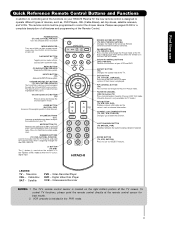
... the remote. The SAT/CBL mode indicator will blink, indicating that the remote will now control your set-top-box or satellite receiver (see page 32 for instructions on your HITACHI Plasma TV, the new remote control is designed to operate different types of the Source Select on the remote. ...The Remote Control The Remote Control In addition to controlling all the functions on how to program the remote to control your set-top-box or ...
... the remote. The SAT/CBL mode indicator will blink, indicating that the remote will now control your set-top-box or satellite receiver (see page 32 for instructions on your HITACHI Plasma TV, the new remote control is designed to operate different types of the Source Select on the remote. ...The Remote Control The Remote Control In addition to controlling all the functions on how to program the remote to control your set-top-box or ...

Owners Guide
Page 24
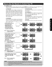
...a more brightness and contrast to toggle between Day (Normal), Day (Dynamic) and Night picture mode settings. Select DAY for day time viewing with more detailed picture (see page 41 for instructions on how to set on or blinks three times to show remote control mode. ¿ » SOURCE SELECT button ... three different freeze modes (see page 55. 24 The Remote Control How to Use the Remote to Control Your TV ³ POWER button Press this button to turn the TV set the remote control to TV mode). ³ · MODE Indicator · » Turns on or off when the remote is in...
...a more brightness and contrast to toggle between Day (Normal), Day (Dynamic) and Night picture mode settings. Select DAY for day time viewing with more detailed picture (see page 41 for instructions on how to set on or blinks three times to show remote control mode. ¿ » SOURCE SELECT button ... three different freeze modes (see page 55. 24 The Remote Control How to Use the Remote to Control Your TV ³ POWER button Press this button to turn the TV set the remote control to TV mode). ³ · MODE Indicator · » Turns on or off when the remote is in...
Owners Guide
Page 25
... size. 16:9 ZOOM Use this aspect to fill it may appear lines at the edge of the picture this is normal operation 25 of the TV. When displaying 16:9 STANDARD 2 it . • Antenna-Analog Channel • S-Video/Video Input (Auto Aspect: Off) • HDMI-480i/480p Input (Auto Aspect: Off) ... from the center towards the edges of the display area in order to Zoom-in once while in all video inputs have independent Aspect Style setting. 2. Vertical position adjustments are placed to the left and right of the image to quickly change the picture format ASPECT ratio. The Remote Control ...
... size. 16:9 ZOOM Use this aspect to fill it may appear lines at the edge of the picture this is normal operation 25 of the TV. When displaying 16:9 STANDARD 2 it . • Antenna-Analog Channel • S-Video/Video Input (Auto Aspect: Off) • HDMI-480i/480p Input (Auto Aspect: Off) ... from the center towards the edges of the display area in order to Zoom-in once while in all video inputs have independent Aspect Style setting. 2. Vertical position adjustments are placed to the left and right of the image to quickly change the picture format ASPECT ratio. The Remote Control ...


