
HP Z210 Convertible Minitower Workstation - Declaration of Conformity
Page 1
... Strasse 140, 71034 Boeblingen, Germany U.S.: Hewlett-Packard, 3000 Hanover St., Palo Alto 94304, U.S.A. 650-857-1501 www.hp.com/go/certificates TPC-F011-WS OPTIONS CATEGORY & DESCRIPTION WLAN REGULATORY MODEL NUMBER WN7600R-MV HP Z210 CMT Workstation Regulatory model number: 1) TPC-F011-WS Product options: All Conforms to the following two conditions: (1) This device may...
... Strasse 140, 71034 Boeblingen, Germany U.S.: Hewlett-Packard, 3000 Hanover St., Palo Alto 94304, U.S.A. 650-857-1501 www.hp.com/go/certificates TPC-F011-WS OPTIONS CATEGORY & DESCRIPTION WLAN REGULATORY MODEL NUMBER WN7600R-MV HP Z210 CMT Workstation Regulatory model number: 1) TPC-F011-WS Product options: All Conforms to the following two conditions: (1) This device may...
HP Z210 CMT Workstation Maintenance and Service Guide
Page 1
HP Z210 CMT Workstation Maintenance and Service Guide
HP Z210 CMT Workstation Maintenance and Service Guide

HP Z210 CMT Workstation Maintenance and Service Guide
Page 3
About this guide This guide provides service and maintenance information for the HP Z210 Convertible Mini Tower (CMT) Workstation. It includes these topics: Guide topics Product overview on page 1 Setting up the operating system on page 16 Restoring the operating system on page 22 ... password security and resetting CMOS on page 150 Connector pins on page 154 System board designators on page 161 Routine Care on page 163 Locating HP resources on page 165 ENWW iii
About this guide This guide provides service and maintenance information for the HP Z210 Convertible Mini Tower (CMT) Workstation. It includes these topics: Guide topics Product overview on page 1 Setting up the operating system on page 16 Restoring the operating system on page 22 ... password security and resetting CMOS on page 150 Connector pins on page 154 System board designators on page 161 Routine Care on page 163 Locating HP resources on page 165 ENWW iii
HP Z210 CMT Workstation Maintenance and Service Guide
Page 16
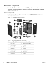
Drive configurations can vary. Figure 1-2 Workstation chassis components Table 1-1 Workstation component descriptions Item Description Item Description 1 Power supply 8 Memory module (DIMM) 2 Side access panel 9 PCIe... ENWW Workstation components This section describes the workstation components, including front and rear panel components. For complete and current information on supported accessories and components for the workstation, see http://partsurfer.hp.com. Chassis components The following figure shows the chassis components of a typical HP Z210 CMT Workstation layout....
Drive configurations can vary. Figure 1-2 Workstation chassis components Table 1-1 Workstation component descriptions Item Description Item Description 1 Power supply 8 Memory module (DIMM) 2 Side access panel 9 PCIe... ENWW Workstation components This section describes the workstation components, including front and rear panel components. For complete and current information on supported accessories and components for the workstation, see http://partsurfer.hp.com. Chassis components The following figure shows the chassis components of a typical HP Z210 CMT Workstation layout....
HP Z210 CMT Workstation Maintenance and Service Guide
Page 17
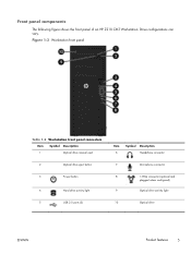
Drive configurations can vary. Front panel components The following figure shows the front panel of an HP Z210 CMT Workstation. Figure 1-3 Workstation front panel Table 1-2 Workstation front panel connectors Item Symbol Description 1 Optical drive manual eject 2 Optical drive eject button 3 Power button 4 Hard drive activity light 5 USB 2.0 ports (3) Item 6 Symbol Description Headphone connector 7 Microphone connector 8 1394a connector (optional and plugged unless configured) 9 Optical drive activity light 10 Optical drive ENWW Product features 5
Drive configurations can vary. Front panel components The following figure shows the front panel of an HP Z210 CMT Workstation. Figure 1-3 Workstation front panel Table 1-2 Workstation front panel connectors Item Symbol Description 1 Optical drive manual eject 2 Optical drive eject button 3 Power button 4 Hard drive activity light 5 USB 2.0 ports (3) Item 6 Symbol Description Headphone connector 7 Microphone connector 8 1394a connector (optional and plugged unless configured) 9 Optical drive activity light 10 Optical drive ENWW Product features 5
HP Z210 CMT Workstation Maintenance and Service Guide
Page 18
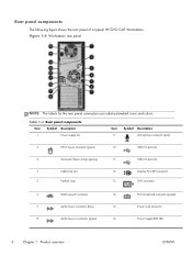
Rear panel components The following figure shows the rear panel of a typical HP Z210 CMT Workstation. Figure 1-4 Workstation rear panel NOTE: The labels for the rear panel connectors use industry-standard icons and colors. Table 1-3 Rear panel components Item Symbol Description 1 Power supply ...
Rear panel components The following figure shows the rear panel of a typical HP Z210 CMT Workstation. Figure 1-4 Workstation rear panel NOTE: The labels for the rear panel connectors use industry-standard icons and colors. Table 1-3 Rear panel components Item Symbol Description 1 Power supply ...

HP Z210 CMT Workstation Maintenance and Service Guide
Page 102
Table 5-6 HP x210 CMT Workstation PCIe compatibility matrix Slot Mechanical compatibility Electrical lanes available 1 x8 connector 4 2 x16 connector 16 3 x1 connector 1 4 x16 connector 4 5 x1 connector 1 Removing an expansion card To ... NOTE: The x1, x4, and x16 designators describe the mechanical length of electrical PCIe lanes routed to determine PCIe card compatibility. Disconnect power from the workstation (see Removing the side access panel on page 62). 2. The number in parentheses lists the number of the slot. For example, x16(4) means that the...
Table 5-6 HP x210 CMT Workstation PCIe compatibility matrix Slot Mechanical compatibility Electrical lanes available 1 x8 connector 4 2 x16 connector 16 3 x1 connector 1 4 x16 connector 4 5 x1 connector 1 Removing an expansion card To ... NOTE: The x1, x4, and x16 designators describe the mechanical length of electrical PCIe lanes routed to determine PCIe card compatibility. Disconnect power from the workstation (see Removing the side access panel on page 62). 2. The number in parentheses lists the number of the slot. For example, x16(4) means that the...
HP Z210 CMT Workstation Maintenance and Service Guide
Page 158
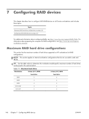
... topics: Topics Maximum RAID hard drive configurations on page 146 Configuring SATA RAID devices on HP workstations for RAID configuration, see http://www.hp.com/support/RAID_FAQs. Maximum RAID hard drive configurations This section lists the maximum number of hard.... TIP: Use the table values to internal workstation configurations that do not use add-in the sections below. Table 7-1 Maximum hard drives Workstation 8.5mm (3.5") SATA hard drive 6.3mm (2.5") SATA hard drive Z800 5 6 Z600 3 4 Z400 4 4 Z210 CMT 3 3 Z210 SFF 2 2 146 Chapter 7 Configuring RAID ...
... topics: Topics Maximum RAID hard drive configurations on page 146 Configuring SATA RAID devices on HP workstations for RAID configuration, see http://www.hp.com/support/RAID_FAQs. Maximum RAID hard drive configurations This section lists the maximum number of hard.... TIP: Use the table values to internal workstation configurations that do not use add-in the sections below. Table 7-1 Maximum hard drives Workstation 8.5mm (3.5") SATA hard drive 6.3mm (2.5") SATA hard drive Z800 5 6 Z600 3 4 Z400 4 4 Z210 CMT 3 3 Z210 SFF 2 2 146 Chapter 7 Configuring RAID ...

HP Z210 Workstation Series User Guide
Page 5
... Product support ...3 Product documentation ...4 Product diagnostics ...5 Product updates ...6 2 Workstation components 7 HP Z210 CMT Workstation components 7 HP Z210 CMT Workstation chassis components 8 HP Z210 CMT Workstation front panel components 9 HP Z210 CMT Workstation rear panel components 10 HP Z210 SFF Workstation components 11 HP Z210 SFF Workstation chassis components 11 HP Z210 SFF Workstation front panel components 12 HP Z210 SFF Workstation rear panel components 13 3 Setting up the workstation 14 Ensuring proper ventilation ...14 Setup procedures ...15 Converting to...
... Product support ...3 Product documentation ...4 Product diagnostics ...5 Product updates ...6 2 Workstation components 7 HP Z210 CMT Workstation components 7 HP Z210 CMT Workstation chassis components 8 HP Z210 CMT Workstation front panel components 9 HP Z210 CMT Workstation rear panel components 10 HP Z210 SFF Workstation components 11 HP Z210 SFF Workstation chassis components 11 HP Z210 SFF Workstation front panel components 12 HP Z210 SFF Workstation rear panel components 13 3 Setting up the workstation 14 Ensuring proper ventilation ...14 Setup procedures ...15 Converting to...
HP Z210 Workstation Series User Guide
Page 6
... Setting up Novell SLED ...28 Setting up SLED on preloaded systems 28 Installing from SLED optical media 28 Installing with the HP driver CD 28 Updating the workstation ...29 Updating the workstation after first boot 29 Upgrading the BIOS 29 Determining current BIOS 29 Upgrading BIOS 30 Upgrading device drivers 30 5 Restoring the... cards 42 Installing an expansion card ...42 9 Installing hard disk drives 44 HDD configuration ...44 Installing a hard disk drive ...45 Installing an HDD in an HP Z210 CMT Workstation 45 vi ENWW
... Setting up Novell SLED ...28 Setting up SLED on preloaded systems 28 Installing from SLED optical media 28 Installing with the HP driver CD 28 Updating the workstation ...29 Updating the workstation after first boot 29 Upgrading the BIOS 29 Determining current BIOS 29 Upgrading BIOS 30 Upgrading device drivers 30 5 Restoring the... cards 42 Installing an expansion card ...42 9 Installing hard disk drives 44 HDD configuration ...44 Installing a hard disk drive ...45 Installing an HDD in an HP Z210 CMT Workstation 45 vi ENWW
HP Z210 Workstation Series User Guide
Page 7
Installing an HDD in an HP Z210 SFF Workstation 47 Installing a secondary HDD or media card reader into a Z210 SFF 51 10 Installing optical disk drives 53 Installing an optical drive in an HP Z210 CMT Workstation 53 Installing an optical drive (mini-tower configuration 53 Installing an optical drive (desktop configuration 55 Installing an optical drive in an HP Z210 SFF Workstation 56 Notice for Blu-ray optical drives 59 Blu-ray movie playback 59 Blu-ray movie playback compatibility and update 59 Index ...60 ENWW vii
Installing an HDD in an HP Z210 SFF Workstation 47 Installing a secondary HDD or media card reader into a Z210 SFF 51 10 Installing optical disk drives 53 Installing an optical drive in an HP Z210 CMT Workstation 53 Installing an optical drive (mini-tower configuration 53 Installing an optical drive (desktop configuration 55 Installing an optical drive in an HP Z210 SFF Workstation 56 Notice for Blu-ray optical drives 59 Blu-ray movie playback 59 Blu-ray movie playback compatibility and update 59 Index ...60 ENWW vii

HP Z210 Workstation Series User Guide
Page 15
ENWW HP Z210 CMT Workstation components 7 2 Workstation components This chapter describes workstation components. For complete and current information on page 11 HP Z210 CMT Workstation components This section describes the HP Z210 Convertible Mini Tower (CMT) Workstation components, including front and rear panel connectors. It includes these topics: Topics HP Z210 CMT Workstation components on page 7 HP Z210 SFF Workstation components on supported accessories and components for the computer, see http://partsurfer.hp.com.
ENWW HP Z210 CMT Workstation components 7 2 Workstation components This chapter describes workstation components. For complete and current information on page 11 HP Z210 CMT Workstation components This section describes the HP Z210 Convertible Mini Tower (CMT) Workstation components, including front and rear panel connectors. It includes these topics: Topics HP Z210 CMT Workstation components on page 7 HP Z210 SFF Workstation components on supported accessories and components for the computer, see http://partsurfer.hp.com.
HP Z210 Workstation Series User Guide
Page 16
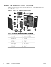
... The following figure shows the chassis components of a typical HP Z210 CMT Workstation layout. Drive configurations can vary. Figure 2-1 HP Z210 CMT Workstation chassis components Table 2-1 HP Z210 CMT Workstation component descriptions Item Description Item Description 1 Power supply 8 Memory module (DIMM) 2 Side access panel 9 PCIe card 3 Rear system fan 10 PCI card 4 Optical drive 11 ...
... The following figure shows the chassis components of a typical HP Z210 CMT Workstation layout. Drive configurations can vary. Figure 2-1 HP Z210 CMT Workstation chassis components Table 2-1 HP Z210 CMT Workstation component descriptions Item Description Item Description 1 Power supply 8 Memory module (DIMM) 2 Side access panel 9 PCIe card 3 Rear system fan 10 PCI card 4 Optical drive 11 ...
HP Z210 Workstation Series User Guide
Page 17
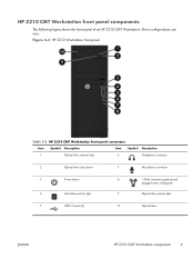
... 7 Microphone connector 3 Power button 4 Hard drive activity light 8 1394a connector (optional and plugged unless configured) 9 Optical drive activity light 5 USB 2.0 ports (3) 10 Optical drive ENWW HP Z210 CMT Workstation components 9 Drive configurations can vary. HP Z210 CMT Workstation front panel components The following figure shows the front panel of an...
... 7 Microphone connector 3 Power button 4 Hard drive activity light 8 1394a connector (optional and plugged unless configured) 9 Optical drive activity light 5 USB 2.0 ports (3) 10 Optical drive ENWW HP Z210 CMT Workstation components 9 Drive configurations can vary. HP Z210 CMT Workstation front panel components The following figure shows the front panel of an...
HP Z210 Workstation Series User Guide
Page 18
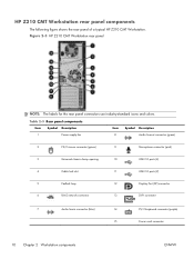
... components The following figure shows the rear panel of a typical HP Z210 CMT Workstation. Figure 2-3 HP Z210 CMT Workstation rear panel NOTE: The labels for the rear panel connectors use industry-standard icons and colors. Table 2-3 Rear panel components Item Symbol Description 1 Power supply ... (DP) connector 6 RJ-45 network connector 13 DVI-I connector 7 Audio line-in connector (blue) 14 PS/2 keyboard connector (purple) 15 Power cord connector 10 Chapter 2 Workstation components ENWW
... components The following figure shows the rear panel of a typical HP Z210 CMT Workstation. Figure 2-3 HP Z210 CMT Workstation rear panel NOTE: The labels for the rear panel connectors use industry-standard icons and colors. Table 2-3 Rear panel components Item Symbol Description 1 Power supply ... (DP) connector 6 RJ-45 network connector 13 DVI-I connector 7 Audio line-in connector (blue) 14 PS/2 keyboard connector (purple) 15 Power cord connector 10 Chapter 2 Workstation components ENWW
HP Z210 Workstation Series User Guide
Page 25
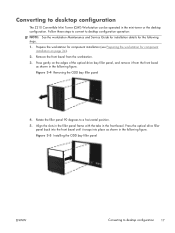
...shown in the following steps. 1. Rotate the filler panel 90 degrees to desktop configuration 17 Converting to desktop configuration The Z210 Convertible Mini Tower (CMT) Workstation can be operated in the front bezel. Follow these steps to convert to desktop configuration operation: NOTE: See the... workstation Maintenance and Service Guide for installation details for component installation on the edges of the optical drive bay filler panel...
...shown in the following steps. 1. Rotate the filler panel 90 degrees to desktop configuration 17 Converting to desktop configuration The Z210 Convertible Mini Tower (CMT) Workstation can be operated in the front bezel. Follow these steps to convert to desktop configuration operation: NOTE: See the... workstation Maintenance and Service Guide for installation details for component installation on the edges of the optical drive bay filler panel...
HP Z210 Workstation Series User Guide
Page 27
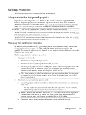
.../support/workstation_manuals/, or see Connecting the monitors on page 23). The HP Z210 CMT workstation provides rear-panel connectors for DisplayPort and DVI-I. (See HP Z210 CMT Workstation rear panel components on page 10.) The HP Z210 SFF workstation provides rear-panel connectors for DisplayPort and VGA. (See HP Z210 SFF Workstation rear panel components on page 21.) NOTE: Monitors with simultaneous output to...
.../support/workstation_manuals/, or see Connecting the monitors on page 23). The HP Z210 CMT workstation provides rear-panel connectors for DisplayPort and DVI-I. (See HP Z210 CMT Workstation rear panel components on page 10.) The HP Z210 SFF workstation provides rear-panel connectors for DisplayPort and VGA. (See HP Z210 SFF Workstation rear panel components on page 21.) NOTE: Monitors with simultaneous output to...
HP Z210 Workstation Series User Guide
Page 53
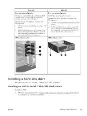
...: ● SATA HDD cables plug into the system board connectors in Preparing for component installation on page 34 to install a hard disk drive in an HP Z210 CMT Workstation To install an HDD: 1. The cables plug into SATA ports starting at SATA port zero. ● Blue SATA ports (labeled zero and one ) support SATA...
...: ● SATA HDD cables plug into the system board connectors in Preparing for component installation on page 34 to install a hard disk drive in an HP Z210 CMT Workstation To install an HDD: 1. The cables plug into SATA ports starting at SATA port zero. ● Blue SATA ports (labeled zero and one ) support SATA...
HP Z210 Workstation Series User Guide
Page 61
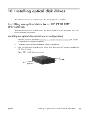
...) 1. Figure 10-1 Installing the guide screws ENWW Installing an optical drive in the workstation. Spare metric M3 screws are stored on page 34 to prepare the workstation for component installation on the side of the optical bay. 3. If necessary, remove the... disk drive (ODD) in an HP Z210 CMT Workstation 53 Follow the procedures described in the minitower and desktop configurations. Installing an optical drive in an HP Z210 CMT Workstation This section describes how to install an optical disk drive in the HP Z210 CMT Workstation in Preparing for component installation. ...
...) 1. Figure 10-1 Installing the guide screws ENWW Installing an optical drive in the workstation. Spare metric M3 screws are stored on page 34 to prepare the workstation for component installation on the side of the optical bay. 3. If necessary, remove the... disk drive (ODD) in an HP Z210 CMT Workstation 53 Follow the procedures described in the minitower and desktop configurations. Installing an optical drive in an HP Z210 CMT Workstation This section describes how to install an optical disk drive in the HP Z210 CMT Workstation in Preparing for component installation. ...
HP Z210 Workstation Series User Guide
Page 63
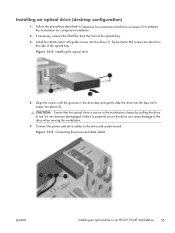
...the side of the optical bay. 3. Align the screws with the grooves in the workstation chassis by pulling the drive to prepare the workstation for component installation. 2. Failure to properly secure the drive can become disengaged. If...from the front of the optical bay. Connect the power and drive cables to the drive when moving the workstation. 5. CAUTION: Ensure that the optical drive is secure in the drive bay and gently slide the drive into...drive and system board. Follow the procedures described in an HP Z210 CMT Workstation 55 Figure 10-4 Installing the optical drive 4.
...the side of the optical bay. 3. Align the screws with the grooves in the workstation chassis by pulling the drive to prepare the workstation for component installation. 2. Failure to properly secure the drive can become disengaged. If...from the front of the optical bay. Connect the power and drive cables to the drive when moving the workstation. 5. CAUTION: Ensure that the optical drive is secure in the drive bay and gently slide the drive into...drive and system board. Follow the procedures described in an HP Z210 CMT Workstation 55 Figure 10-4 Installing the optical drive 4.


