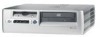
HP Dc5000 Power Supply Removal - Compaq Business Desktop
HP Dc5000 Power Supply Removal
Related Manual Pages
Related Videos

How to remove an HP DC5000 SFF Power Supply
Duration: 7:37
Total Views: 1,068
Duration: 7:37
Total Views: 1,068
Similar Questions

Dc5000 Sff How To Remove Power Supply
(Posted by ruSt 9 years ago)

How To Repair Hp Compaq Dc5000 Sff Power Supply
(Posted by shainbkso 10 years ago)


Power Supply Led And Lan Led Flashes Simultaneusly And Does Not Start
i have a problem power supply led and lan led flashes and the pc does not start, is it a power suppl...
i have a problem power supply led and lan led flashes and the pc does not start, is it a power suppl...
(Posted by ivan88880 12 years ago)

Assembly Take Aprt
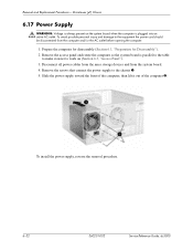
Power Supply Removal
(Posted by debardir 13 years ago)