
English Manual
Page 1
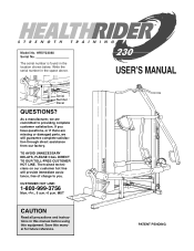
.... TO AVOID UNNECESSARY DELAYS, PLEASE CALL DIRECT TO OUR TOLL-FREE CUSTOMER HOT LINE. Serial Number Decal QUESTIONS? MST CAUTION Read all precautions and instructions in the location shown below. The serial number is found in this manual before using this manual for future reference. ¨ USERÕS MANUAL PATENT PENDING Write the serial number in the space above. HRSY23080 Serial No. Model No. If you have questions...
.... TO AVOID UNNECESSARY DELAYS, PLEASE CALL DIRECT TO OUR TOLL-FREE CUSTOMER HOT LINE. Serial Number Decal QUESTIONS? MST CAUTION Read all precautions and instructions in the location shown below. The serial number is found in this manual before using this manual for future reference. ¨ USERÕS MANUAL PATENT PENDING Write the serial number in the space above. HRSY23080 Serial No. Model No. If you have questions...
English Manual
Page 2
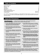
... press arms, butterfly arms, leg lever, lat bar or ab strap while weights are raised. If you are using the home gym system. 1. ICON assumes no responsibility for persons over the age of 35 or persons with great force. 13. Cover the floor or carpet beneath the home gym system for foot protection when exercising. 12. Table of Contents Important Precautions 2 Before You Begin 3 Assembly 4 Cable Diagram 19 Adjustment 20 Weight Resistance Chart...
... press arms, butterfly arms, leg lever, lat bar or ab strap while weights are raised. If you are using the home gym system. 1. ICON assumes no responsibility for persons over the age of 35 or persons with great force. 13. Cover the floor or carpet beneath the home gym system for foot protection when exercising. 12. Table of Contents Important Precautions 2 Before You Begin 3 Assembly 4 Cable Diagram 19 Adjustment 20 Weight Resistance Chart...
English Manual
Page 3
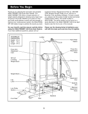
... a decal attached to the HEALTHRIDER¨ 230 Home Gym System (see the front cover of this manual carefully before calling. For your benefit, read this manual). If you , please note the product model number and serial number before using the HEALTHRIDER¨ 230 Home Gym System. Length: 67 in . until 6 p.m. Press Arm Adjustment Cam Shroud Covering Weight Stack Lat Bar High Pulley Station Press Arm Adjustment Knob Press Arms Weight Stack Leg Lever Low Pulley Station Foot Plate Seat Backrest 3 Adjustment Disc Butterfly Arm Backrest Adjustment Knob Mountain Time...
... a decal attached to the HEALTHRIDER¨ 230 Home Gym System (see the front cover of this manual carefully before calling. For your benefit, read this manual). If you , please note the product model number and serial number before using the HEALTHRIDER¨ 230 Home Gym System. Length: 67 in . until 6 p.m. Press Arm Adjustment Cam Shroud Covering Weight Stack Lat Bar High Pulley Station Press Arm Adjustment Knob Press Arms Weight Stack Leg Lever Low Pulley Station Foot Plate Seat Backrest 3 Adjustment Disc Butterfly Arm Backrest Adjustment Knob Mountain Time...
English Manual
Page 4
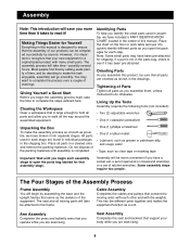
... cables and pulleys that you operate while you to walk all moving arms with each stage are exercising. 4 Arm Assembly Completes the press and butterfly arms that connect the moving parts will save you are found in individual packages in this product, be completed successfully by setting aside plenty of ratchet wrenches. Lining Up the Tools Assembly requires the following tools (not included): ¥ Two (2) adjustable...
... cables and pulleys that you operate while you to walk all moving arms with each stage are exercising. 4 Arm Assembly Completes the press and butterfly arms that connect the moving parts will save you are found in individual packages in this product, be completed successfully by setting aside plenty of ratchet wrenches. Lining Up the Tools Assembly requires the following tools (not included): ¥ Two (2) adjustable...
English Manual
Page 5
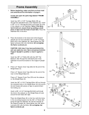
...information on the Weight Base (5). Hand tighten two 3/8Ó Nylon Locknuts (50) onto the Bolts. Press a 2Ó Square Cover Cap (33) onto the sidearm on page 4. Place the Weight Base (5) on the floor with the holes in the sidearm on the Weight Base (5) and secure the bolt... Support Upright (3) over the indicated 3/8Ó x 2 3/4Ó Carriage Bolts (45) in the Stabilizer (4). Locate and open the parts bag labeled ÒFRAME ASSEMBLY.Ó Insert four 3/8Ó x 2 3/4Ó Carriage Bolts (45) up through the indicated holes in the Weight Base (5) and secure the bolt heads...
...information on the Weight Base (5). Hand tighten two 3/8Ó Nylon Locknuts (50) onto the Bolts. Press a 2Ó Square Cover Cap (33) onto the sidearm on page 4. Place the Weight Base (5) on the floor with the holes in the sidearm on the Weight Base (5) and secure the bolt... Support Upright (3) over the indicated 3/8Ó x 2 3/4Ó Carriage Bolts (45) in the Stabilizer (4). Locate and open the parts bag labeled ÒFRAME ASSEMBLY.Ó Insert four 3/8Ó x 2 3/4Ó Carriage Bolts (45) up through the indicated holes in the Weight Base (5) and secure the bolt heads...
English Manual
Page 8
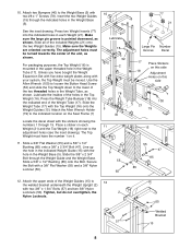
... Weight Guides (15). Secure the Bolt with the stickers showing the numbers 1 through 15. Slide the Weight Tube (17) with two #8 x 1Ó Screws (78). 10. Attach two Bumpers (40) to the indicated location on each Weight (21). For packaging purposes, the Top Weight (16) is pointed downward, as shown. Lubricate the insides of the included Weights (21) onto the two Weight Guides (15). Press the Weight...
... Weight Guides (15). Secure the Bolt with the stickers showing the numbers 1 through 15. Slide the Weight Tube (17) with two #8 x 1Ó Screws (78). 10. Attach two Bumpers (40) to the indicated location on each Weight (21). For packaging purposes, the Top Weight (16) is pointed downward, as shown. Lubricate the insides of the included Weights (21) onto the two Weight Guides (15). Press the Weight...

English Manual
Page 9
.... Assemble the Left Adjustment Disc (26) in its entire length. Wet the end of each Arm. Orient one Butterfly Arm (10) as shown and slide it and the bracket on the Retainer Ring bend towards the Cover Cap (see inset drawing). Note: Use the Cover Cap to tap on the crossbar attached to the Main Upright (1). Secure the Press Frame...
.... Assemble the Left Adjustment Disc (26) in its entire length. Wet the end of each Arm. Orient one Butterfly Arm (10) as shown and slide it and the bracket on the Retainer Ring bend towards the Cover Cap (see inset drawing). Note: Use the Cover Cap to tap on the crossbar attached to the Main Upright (1). Secure the Press Frame...
English Manual
Page 10
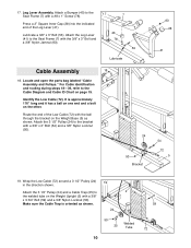
... has a ball on one end and a bolt on page 19. Locate and open the parts bag labeled ÒCable Assembly and Pulleys.Ó For Cable identification and routing during steps 18Ñ39, refer to the 17 Seat Frame (7) with a 3/8Ó x 3 3/4Ó Bolt (59) and a 3/8Ó Nylon Locknut (50). Lubricate a 3/8Ó x 3Ó Bolt (53). It is oriented as shown. Identify the Low Cable (72). Leg Lever Assembly.
... has a ball on one end and a bolt on page 19. Locate and open the parts bag labeled ÒCable Assembly and Pulleys.Ó For Cable identification and routing during steps 18Ñ39, refer to the 17 Seat Frame (7) with a 3/8Ó x 3 3/4Ó Bolt (59) and a 3/8Ó Nylon Locknut (50). Lubricate a 3/8Ó x 3Ó Bolt (53). It is oriented as shown. Identify the Low Cable (72). Leg Lever Assembly.
English Manual
Page 11
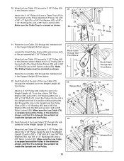
...; x 2Ó Bolt (54) and a 3/8Ó Nylon Locknut (50). Locate the Small Pulley Frame (22) and remove both of the Low Cable (72) through the indicated slot in the direction shown. Route the Low Cable (72) through the indicated slot in the direction shown. Wrap the Low Cable (72) around a 3 1/2Ó Pulley (24) in the Weight Upright (2) from below . 22 Welded Rod Attach a 3 1/2Ó Pulley (24...
...; x 2Ó Bolt (54) and a 3/8Ó Nylon Locknut (50). Locate the Small Pulley Frame (22) and remove both of the Low Cable (72) through the indicated slot in the direction shown. Route the Low Cable (72) through the indicated slot in the direction shown. Wrap the Low Cable (72) around a 3 1/2Ó Pulley (24) in the Weight Upright (2) from below . 22 Welded Rod Attach a 3 1/2Ó Pulley (24...

English Manual
Page 13
... use a 3/8Ó Nylon Locknut unless the Bolt slides out during the following step. 31 73 Riser 25 24 46 5 13 Make sure the Cable Trap is on the correct side of the Pulley 53 attached in the direction shown and route it back down through the Pulley, Cable Trap and riser. Attach the 3 1/2Ó Pulley (24) inside the bracket on the Main Upright...
... use a 3/8Ó Nylon Locknut unless the Bolt slides out during the following step. 31 73 Riser 25 24 46 5 13 Make sure the Cable Trap is on the correct side of the Pulley 53 attached in the direction shown and route it back down through the Pulley, Cable Trap and riser. Attach the 3 1/2Ó Pulley (24) inside the bracket on the Main Upright...

English Manual
Page 14
... clarity, drawing 35A shows some parts removed. 34. Attach the 3 1/2Ó Pulley (24) and a Cable Trap (25) to the sidearm on the Weight Base (5) by sliding the Pulley and Cable Trap onto the 3/8Ó x 3 1/2Ó Bolt (56) inserted earlier. Tighten a 3/8Ó Nylon Jamnut (63) onto the Bolt. Wrap the High Cable (73) around a 3 1/2Ó Pulley (24) in the direction shown. Thread a 3/8Ó Nylon Locknut...
... clarity, drawing 35A shows some parts removed. 34. Attach the 3 1/2Ó Pulley (24) and a Cable Trap (25) to the sidearm on the Weight Base (5) by sliding the Pulley and Cable Trap onto the 3/8Ó x 3 1/2Ó Bolt (56) inserted earlier. Tighten a 3/8Ó Nylon Jamnut (63) onto the Bolt. Wrap the High Cable (73) around a 3 1/2Ó Pulley (24) in the direction shown. Thread a 3/8Ó Nylon Locknut...

English Manual
Page 15
... end of the High Cable (73) to 50 the lower half of clarity, some parts have 92 25 been removed from the drawing. 39. Identify the Butterfly Cable (92). Route the High Cable (73) through the slot in the direction shown. 23 Attach the 3 1/2Ó Pulley (24) and a Cable Trap (25) to the Leg Lever (41) with a 3/8Ó x 2Ó Bolt (54) and a 3/8Ó...
... end of the High Cable (73) to 50 the lower half of clarity, some parts have 92 25 been removed from the drawing. 39. Identify the Butterfly Cable (92). Route the High Cable (73) through the slot in the direction shown. 23 Attach the 3 1/2Ó Pulley (24) and a Cable Trap (25) to the Leg Lever (41) with a 3/8Ó x 2Ó Bolt (54) and a 3/8Ó...

English Manual
Page 16
... the end of all Cables are on the lower edge of both the Cables and the Pulleys move smoothly. 40. Locate and open the parts bag labeled ÒSeat 47 Assembly.Ó 72 68 48 89 17 19 21 98 38 50 51 39 Press a 1 1/4Ó Square Inner Cap (98) into the Weight Tube until all Pulleys. Slide the Backrest Adjustment Tube (39) onto...
... the end of all Cables are on the lower edge of both the Cables and the Pulleys move smoothly. 40. Locate and open the parts bag labeled ÒSeat 47 Assembly.Ó 72 68 48 89 17 19 21 98 38 50 51 39 Press a 1 1/4Ó Square Inner Cap (98) into the Weight Tube until all Pulleys. Slide the Backrest Adjustment Tube (39) onto...

English Manual
Page 17
...tighten the Bolt yet. 46 Bracket 80 36 5 2 36 47. Attach both Shrouds (35, 36). Attach the Right Shroud (36) to the indicated bracket on the opposite side of the 1/4Ó x 5/8Ó Bolts (80) used to attach both Shrouds (35, 36) to the indicated brackets on the Weight Upright (2) with a 1/4Ó x 5/8Ó Bolt (80). Top Bar...5/8Ó Bolts (80). Press two 3/4Ó Round Inner Caps (43) into the Leg Lever (41). Go back and fully tighten all of 47 2 the weight stack. Identify the Right Shroud (36) which is the one Pad Tube (42) into the Seat Frame ...
...tighten the Bolt yet. 46 Bracket 80 36 5 2 36 47. Attach both Shrouds (35, 36). Attach the Right Shroud (36) to the indicated bracket on the opposite side of the 1/4Ó x 5/8Ó Bolts (80) used to attach both Shrouds (35, 36) to the indicated brackets on the Weight Upright (2) with a 1/4Ó x 5/8Ó Bolt (80). Top Bar...5/8Ó Bolts (80). Press two 3/4Ó Round Inner Caps (43) into the Leg Lever (41). Go back and fully tighten all of 47 2 the weight stack. Identify the Right Shroud (36) which is the one Pad Tube (42) into the Seat Frame ...
English Manual
Page 18
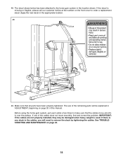
... remaining parts will need to order a replacement decal. The use of the cables does not move smoothly over the pulleys. See TROUBLESHOOTING AND MAINTENANCE on the front cover to remove the slack by tightening the cables. If the decal is any slack in ADJUSTMENT, beginning on page 20 of this manual. Before using the home gym system, pull each cable a few times to the home gym system in the appropriate location. 48...
... remaining parts will need to order a replacement decal. The use of the cables does not move smoothly over the pulleys. See TROUBLESHOOTING AND MAINTENANCE on the front cover to remove the slack by tightening the cables. If the decal is any slack in ADJUSTMENT, beginning on page 20 of this manual. Before using the home gym system, pull each cable a few times to the home gym system in the appropriate location. 48...
English Manual
Page 20
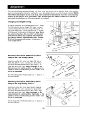
... the home gym system can be attached between the Lat Bar and the High Cable with a Cable Clip (69). IMPORTANT: When attaching the lat bar or ab strap, make sure that the attachments are in the correct starting position for the exercise to the cables and pulleys, the amount of resistance at each part of the exercise will go. Note: Due to be performed. Make sure you insert the Weight Pin...
... the home gym system can be attached between the Lat Bar and the High Cable with a Cable Clip (69). IMPORTANT: When attaching the lat bar or ab strap, make sure that the attachments are in the correct starting position for the exercise to the cables and pulleys, the amount of resistance at each part of the exercise will go. Note: Due to be performed. Make sure you insert the Weight Pin...
English Manual
Page 22
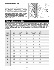
... friction between the cables, pulleys, and weight guides. weight plates. This chart shows the resistance for Model No. Pull out the Adjustment Knob (66) on the previous page. top weight; ask for the five extra weight plates included with the Weight Expansion Set (see No. 16-20 below shows the approximate weight resistance at each have three adjustment holes for use during regular exercises. Adjusting the Butterfly Arms Make sure the...
... friction between the cables, pulleys, and weight guides. weight plates. This chart shows the resistance for Model No. Pull out the Adjustment Knob (66) on the previous page. top weight; ask for the five extra weight plates included with the Weight Expansion Set (see No. 16-20 below shows the approximate weight resistance at each have three adjustment holes for use during regular exercises. Adjusting the Butterfly Arms Make sure the...
English Manual
Page 23
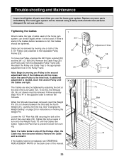
...;Changing the Weight SettingÓ on page 20 for instructions on the home gym system, can also be replaced, see ORDERING REPLACEMENT PARTS on the back cover of the Low Cable (72). If the Cables need to remove the Shrouds. Adjustment Holes 54 25 72 Bolt 68 17 21 23 Re-attach the Pulley and Cable Trap to the appropriate adjustment hole in the opposite order to be tightened by adjusting the bolt...
...;Changing the Weight SettingÓ on page 20 for instructions on the home gym system, can also be replaced, see ORDERING REPLACEMENT PARTS on the back cover of the Low Cable (72). If the Cables need to remove the Shrouds. Adjustment Holes 54 25 72 Bolt 68 17 21 23 Re-attach the Pulley and Cable Trap to the appropriate adjustment hole in the opposite order to be tightened by adjusting the bolt...

English Manual
Page 27
Specifications are subject to change without notice. Qty. Model No. Main Upright 53 9 Weight Upright 54 6 Support Upright 55 28 Stabilizer 56 1 Weight Base 57 4 Seat Base 58 4 Seat Frame 59 2 Press frame 60 1 Top Frame 61 1 Butterfly Arm 62 2 Press Frame Knob 63 4 Backrest 64 2 Seat 65 2 Press Arm Adjustment Frame 66 2 Weight Guide 67 1 Top Weight 68 1 Weight Tube 69 2 Weight Tube Bumper 70 2 Weight Pin 71 4 Weight Cover 72 1 Weight 73 1 Small Pulley Frame 74 4 Adjustable Pulley Frame 75 1 3 1/2Ó...
Specifications are subject to change without notice. Qty. Model No. Main Upright 53 9 Weight Upright 54 6 Support Upright 55 28 Stabilizer 56 1 Weight Base 57 4 Seat Base 58 4 Seat Frame 59 2 Press frame 60 1 Top Frame 61 1 Butterfly Arm 62 2 Press Frame Knob 63 4 Backrest 64 2 Seat 65 2 Press Arm Adjustment Frame 66 2 Weight Guide 67 1 Top Weight 68 1 Weight Tube 69 2 Weight Tube Bumper 70 2 Weight Pin 71 4 Weight Cover 72 1 Weight 73 1 Small Pulley Frame 74 4 Adjustable Pulley Frame 75 1 3 1/2Ó...
English Manual
Page 29
... us assist you . The SERIAL NUMBER of the product (see the PART LIST and EXPLODED DRAWING attached at 1-800-999-3756, Monday through Friday, 6 a.m. The warranty extended hereunder is in workmanship and material, under this manual). This warranty extends only to you specific legal rights. Mountain Time (excluding holidays). Accordingly, the above is limited to replacing or repairing, at ICON's option, the product...
... us assist you . The SERIAL NUMBER of the product (see the PART LIST and EXPLODED DRAWING attached at 1-800-999-3756, Monday through Friday, 6 a.m. The warranty extended hereunder is in workmanship and material, under this manual). This warranty extends only to you specific legal rights. Mountain Time (excluding holidays). Accordingly, the above is limited to replacing or repairing, at ICON's option, the product...

