
User Manual
Page 3
... 2012 GIGA-BYTE TECHNOLOGY CO., LTD. No part of GIGABYTE. Disclaimer Information in this manual is protected by copyright laws...; For detailed product information, carefully read the User's Manual. Check your motherboard looks like this product, GIGABYTE provides the following types of documentations: For quick set-up of the motherboard is the property... may be made by any form or by GIGABYTE without GIGABYTE's prior written permission. For product-related information, check on our website at: http://www.gigabyte.com Identifying Your Motherboard Revision The revision number...
... 2012 GIGA-BYTE TECHNOLOGY CO., LTD. No part of GIGABYTE. Disclaimer Information in this manual is protected by copyright laws...; For detailed product information, carefully read the User's Manual. Check your motherboard looks like this product, GIGABYTE provides the following types of documentations: For quick set-up of the motherboard is the property... may be made by any form or by GIGABYTE without GIGABYTE's prior written permission. For product-related information, check on our website at: http://www.gigabyte.com Identifying Your Motherboard Revision The revision number...
User Manual
Page 4
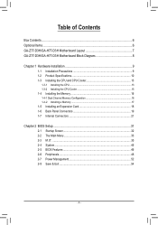
Table of Contents Box Contents...6 Optional Items...6 GA-Z77-D3H/GA-H77-D3H Motherboard Layout 7 GA-Z77-D3H/GA-H77-D3H Motherboard Block Diagram 8 Chapter 1 Hardware Installation 9 1-1 Installation Precautions 9 1-2 Product Specifications 10 1-3 Installing the CPU and CPU ... 1-4-2 Installing a Memory 17 1-5 Installing an Expansion Card 18 1-6 Back Panel Connectors 19 1-7 Internal Connectors 21 Chapter 2 BIOS Setup 31 2-1 Startup Screen 32 2-2 The Main Menu 33 2-3 M.I.T...35 2-4 System...45 2-5 BIOS Features 46 2-6 Peripherals...48 2-7 Power Management 52 2-8 Save & Exit...54 - 4 -
Table of Contents Box Contents...6 Optional Items...6 GA-Z77-D3H/GA-H77-D3H Motherboard Layout 7 GA-Z77-D3H/GA-H77-D3H Motherboard Block Diagram 8 Chapter 1 Hardware Installation 9 1-1 Installation Precautions 9 1-2 Product Specifications 10 1-3 Installing the CPU and CPU ... 1-4-2 Installing a Memory 17 1-5 Installing an Expansion Card 18 1-6 Back Panel Connectors 19 1-7 Internal Connectors 21 Chapter 2 BIOS Setup 31 2-1 Startup Screen 32 2-2 The Main Menu 33 2-3 M.I.T...35 2-4 System...45 2-5 BIOS Features 46 2-6 Peripherals...48 2-7 Power Management 52 2-8 Save & Exit...54 - 4 -
User Manual
Page 5
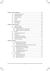
... 56 3-4 Contact...57 3-5 System...57 3-6 Download Center 58 3-7 New Program 58 Chapter 4 Unique Features 59 4-1 Xpress Recovery2 59 4-2 BIOS Update Utilities 62 4-2-1 Updating the BIOS with the Q-Flash Utility 62 4-2-2 Updating the BIOS with the @BIOS Utility 65 4-3 Q-Share...66 4-4 eXtreme Hard Drive (X.H.D 67 4-5 Auto Green...68 4-6 Intel Rapid Start Technology 69 4-7 Intel Smart...
... 56 3-4 Contact...57 3-5 System...57 3-6 Download Center 58 3-7 New Program 58 Chapter 4 Unique Features 59 4-1 Xpress Recovery2 59 4-2 BIOS Update Utilities 62 4-2-1 Updating the BIOS with the Q-Flash Utility 62 4-2-2 Updating the BIOS with the @BIOS Utility 65 4-3 Q-Share...66 4-4 eXtreme Hard Drive (X.H.D 67 4-5 Auto Green...68 4-6 Intel Rapid Start Technology 69 4-7 Intel Smart...
User Manual
Page 8
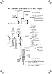
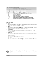
GA-Z77-D3H/GA-H77-D3H Motherboard Block Diagram 1 PCI Express x16 CPU CLK+/- (100 MHz) PCIe CLK (100 MHz) LGA1155 CPU DDR3 1600(Note 1)/1333/1066 MHz Dual Channel Memory PCI Express Bus x16 DMI 2.0 FDI D-Sub LAN 2 USB 3.0/2.0 RJ45 DVI-D HDMI Dual BIOS Atheros GbE LAN Etron EJ168 PCI Express Bus x1 ... MIC Line Out Line In S/PDIF Out 2 PCI PCI CLK (33 MHz) j Only for GA-H77-D3H. (Note 1) To support DDR3 1600 MHz, you must install an Intel 22nm (Ivy Bridge) CPU. (Note 2) In Windows XP, the Intel USB 3.0 ports can support up to USB 2.0 transfer speed. - 8 - k Only for GA-Z77-D3H.
GA-Z77-D3H/GA-H77-D3H Motherboard Block Diagram 1 PCI Express x16 CPU CLK+/- (100 MHz) PCIe CLK (100 MHz) LGA1155 CPU DDR3 1600(Note 1)/1333/1066 MHz Dual Channel Memory PCI Express Bus x16 DMI 2.0 FDI D-Sub LAN 2 USB 3.0/2.0 RJ45 DVI-D HDMI Dual BIOS Atheros GbE LAN Etron EJ168 PCI Express Bus x1 ... MIC Line Out Line In S/PDIF Out 2 PCI PCI CLK (33 MHz) j Only for GA-H77-D3H. (Note 1) To support DDR3 1600 MHz, you must install an Intel 22nm (Ivy Bridge) CPU. (Note 2) In Windows XP, the Intel USB 3.0 ports can support up to USB 2.0 transfer speed. - 8 - k Only for GA-Z77-D3H.
User Manual
Page 12
... Hardware Installation - 12 - j Only for Microsoft® Windows 7/XP ATX Form Factor; 30.5cm x 24.4cm * GIGABYTE reserves the right to make any changes to the integrated graphics port on the CPU/system cooler you install. 2 x 64 ...Mbit flash Use of licensed AMI EFI BIOS Support for DualBIOS™ PnP 1.0a, DMI 2.0, SM BIOS 2.6, ACPI 2.0a Support for @BIOS Support for Q-Flash Support for Xpress Install Support for Xpress Recovery2 Support for ... the product specifications and product-related information without prior notice. Support for GA-Z77-D3H.
... Hardware Installation - 12 - j Only for Microsoft® Windows 7/XP ATX Form Factor; 30.5cm x 24.4cm * GIGABYTE reserves the right to make any changes to the integrated graphics port on the CPU/system cooler you install. 2 x 64 ...Mbit flash Use of licensed AMI EFI BIOS Support for DualBIOS™ PnP 1.0a, DMI 2.0, SM BIOS 2.6, ACPI 2.0a Support for @BIOS Support for Q-Flash Support for Xpress Install Support for Xpress Recovery2 Support for ... the product specifications and product-related information without prior notice. Support for GA-Z77-D3H.
User Manual
Page 16
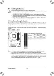
It is installed. 2. A memory module can be used . (Go to GIGABYTE's website for the latest supported memory speeds and memory modules.) • Always turn off the computer and unplug the power cord from the power outlet ... recommend that the motherboard supports the memory. For optimum performance, when enabling Dual Channel mode with two or four memory modules, it is installed, the BIOS will double the original memory bandwidth. Hardware Installation - 16 - After the memory is recommended that memory of the memory. If you are divided into two...
It is installed. 2. A memory module can be used . (Go to GIGABYTE's website for the latest supported memory speeds and memory modules.) • Always turn off the computer and unplug the power cord from the power outlet ... recommend that the motherboard supports the memory. For optimum performance, when enabling Dual Channel mode with two or four memory modules, it is installed, the BIOS will double the original memory bandwidth. Hardware Installation - 16 - After the memory is recommended that memory of the memory. If you are divided into two...

User Manual
Page 18
... is securely seated in the slot. 3. Hardware Installation - 18 - Turn on the top edge of the PCI Express slot to make any required BIOS changes for your expansion card. • Always turn off the computer and unplug the power cord from the power outlet before you begin to prevent... Card: • Installing a Graphics Card: Gently push down on the card are completely inserted into the PCI Express slot. If necessary, go to BIOS Setup to release the card and then pull the card straight up from the chassis back panel. 2. Make sure the card is fully inserted into...
... is securely seated in the slot. 3. Hardware Installation - 18 - Turn on the top edge of the PCI Express slot to make any required BIOS changes for your expansion card. • Always turn off the computer and unplug the power cord from the power outlet before you begin to prevent... Card: • Installing a Graphics Card: Gently push down on the card are completely inserted into the PCI Express slot. If necessary, go to BIOS Setup to release the card and then pull the card straight up from the chassis back panel. 2. Make sure the card is fully inserted into...
User Manual
Page 20
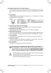
... output ports: D-Sub, DVI-D, and HDMI. The audio jacks can be connected to connect front speakers in operating system environment only, but not during the BIOS Setup or POST process.
... output ports: D-Sub, DVI-D, and HDMI. The audio jacks can be connected to connect front speakers in operating system environment only, but not during the BIOS Setup or POST process.
User Manual
Page 23
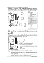
... lost. 3/4) CPU_FAN/SYS_FAN1/SYS_FAN2/SYS_FAN3 (Fan Headers) All fan headers on the headers. 5) BAT (Battery) The battery provides power to keep the values (such as BIOS configurations, date, and time information) in the CMOS when the computer is the ground wire). Definition 1 GND 2 +12V 3 Sense 4 Speed Control • Be sure to...
... lost. 3/4) CPU_FAN/SYS_FAN1/SYS_FAN2/SYS_FAN3 (Fan Headers) All fan headers on the headers. 5) BAT (Battery) The battery provides power to keep the values (such as BIOS configurations, date, and time information) in the CMOS when the computer is the ground wire). Definition 1 GND 2 +12V 3 Sense 4 Speed Control • Be sure to...
User Manual
Page 25
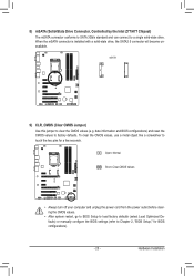
... (select Load Optimized Defaults) or manually configure the BIOS settings (refer to Chapter 2, "BIOS Setup," for a few seconds. F_AUDIO(H) F_PANEL(NH) F_PANEL (H61M-D2) DB_PORT 8) mSATA (Solid-State Drive Connector, Controlled by the Intel Z77/H77 Chipset) The mSATA connector conforms to SATA 3Gb.../s standard and can connect to clear the CMOS values (e.g. To clear the CMOS values, use a metal object like a screwdriver to factory defaults. date information and BIOS configurations) and reset the...
... (select Load Optimized Defaults) or manually configure the BIOS settings (refer to Chapter 2, "BIOS Setup," for a few seconds. F_AUDIO(H) F_PANEL(NH) F_PANEL (H61M-D2) DB_PORT 8) mSATA (Solid-State Drive Connector, Controlled by the Intel Z77/H77 Chipset) The mSATA connector conforms to SATA 3Gb.../s standard and can connect to clear the CMOS values (e.g. To clear the CMOS values, use a metal object like a screwdriver to factory defaults. date information and BIOS configurations) and reset the...
User Manual
Page 26
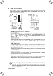
...+ PWR+ PWR- The LED keeps blinking when the system is in S1 sleep state. When connecting your system using the power switch (refer to Chapter 2, "BIOS Setup," "Power Management," for more information). • SPEAK (Speaker, Orange): Connects to the reset switch on the chassis front panel. Hard Drive Activity LED Reset...
...+ PWR+ PWR- The LED keeps blinking when the system is in S1 sleep state. When connecting your system using the power switch (refer to Chapter 2, "BIOS Setup," "Power Management," for more information). • SPEAK (Speaker, Orange): Connects to the reset switch on the chassis front panel. Hard Drive Activity LED Reset...
User Manual
Page 31
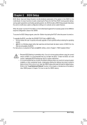
...not alter the default settings (unless you not flash the BIOS. To upgrade the BIOS, use either the GIGABYTE Q-Flash or @BIOS utility. • Q-Flash allows the user to quickly and easily upgrade or back up BIOS without entering the operating system. • @BIOS is a Windows-based utility that allows the user to... to the "Load Optimized Defaults" section in this chapter or introductions of the battery/ clear CMOS jumper in the CMOS on . Chapter 2 BIOS Setup BIOS (Basic Input and Output System) records hardware parameters of the system in Chapter 1 for how to clear the CMOS values.) - 31...
...not alter the default settings (unless you not flash the BIOS. To upgrade the BIOS, use either the GIGABYTE Q-Flash or @BIOS utility. • Q-Flash allows the user to quickly and easily upgrade or back up BIOS without entering the operating system. • @BIOS is a Windows-based utility that allows the user to... to the "Load Optimized Defaults" section in this chapter or introductions of the battery/ clear CMOS jumper in the CMOS on . Chapter 2 BIOS Setup BIOS (Basic Input and Output System) records hardware parameters of the system in Chapter 1 for how to clear the CMOS values.) - 31...

User Manual
Page 32
...information. : BOOT MENU Boot Menu allows you to set the first boot device without having to enter BIOS Setup first. BIOS Setup - 32 - Function Keys Function Keys: : BIOS SETUP\Q-FLASH Press the key to enter BIOS Setup or to access the Q-Flash utility in Boot Menu is effective for one time only. 2-1... Startup Screen The following startup Logo screen will still be based on BIOS Setup settings. : Q-FLASH Press the key to access the Q-Flash utility directly without entering BIOS Setup. In Boot Menu, use the up arrow key or the down arrow key to select the...
...information. : BOOT MENU Boot Menu allows you to set the first boot device without having to enter BIOS Setup first. BIOS Setup - 32 - Function Keys Function Keys: : BIOS SETUP\Q-FLASH Press the key to enter BIOS Setup or to access the Q-Flash utility in Boot Menu is effective for one time only. 2-1... Startup Screen The following startup Logo screen will still be based on BIOS Setup settings. : Q-FLASH Press the key to access the Q-Flash utility directly without entering BIOS Setup. In Boot Menu, use the up arrow key or the down arrow key to select the...
User Manual
Page 33
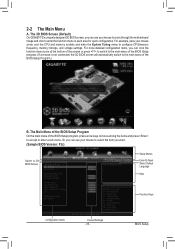
... On GIGABYTE's uniquely designed 3D BIOS screen, you can click the function menu icons at the bottom of the screen or press to switch to the main menu of the BIOS Setup program. (If a mouse is not connected, the 3D BIOS screen will automatically switch to the main menu of the BIOS Setup program... and memory sockets and enter the System Tuning menu to accept or enter a sub-menu. For more detailed configuration items, you want. (Sample BIOS Version: F3c) Switch to enter the function menu in each area for quick configuration. For example, pass your mouse to select the item you ...
... On GIGABYTE's uniquely designed 3D BIOS screen, you can click the function menu icons at the bottom of the screen or press to switch to the main menu of the BIOS Setup program. (If a mouse is not connected, the 3D BIOS screen will automatically switch to the main menu of the BIOS Setup program... and memory sockets and enter the System Tuning menu to accept or enter a sub-menu. For more detailed configuration items, you want. (Sample BIOS Version: F3c) Switch to enter the function menu in each area for quick configuration. For example, pass your mouse to select the item you ...
User Manual
Page 34
...this menu to configure all the power-saving functions. „ Save & Exit Save all peripheral devices, such as an image and save the current BIOS settings to a profile or load optimized defaults for optimal-performance system operations. • If the system is not stable as usual, load optimized ...defaults to set your system to its defaults. • The BIOS Setup menus described in the BIOS Setup program to the CMOS and exit BIOS Setup. BIOS Setup Program Function Keys Move the selection bar to select a setup menu Move the selection bar to ...
...this menu to configure all the power-saving functions. „ Save & Exit Save all peripheral devices, such as an image and save the current BIOS settings to a profile or load optimized defaults for optimal-performance system operations. • If the system is not stable as usual, load optimized ...defaults to set your system to its defaults. • The BIOS Setup menus described in the BIOS Setup program to the CMOS and exit BIOS Setup. BIOS Setup Program Function Keys Move the selection bar to select a setup menu Move the selection bar to ...

User Manual
Page 35
... the CMOS values and reset the board to default values.) This section provides information on your overall system configurations. This page is dependent on the BIOS version, CPU base clock, CPU frequency, memory frequency, total memory size , CPU temperature, Vcore, and memory voltage. - 35 - Whether the system will work stably with... system's failure to CPU, chipset, or memory and reduce the useful life of these components. Incorrectly doing overclock/overvoltage may result in damage to boot. 2-3 M.I.T. BIOS Setup
... the CMOS values and reset the board to default values.) This section provides information on your overall system configurations. This page is dependent on the BIOS version, CPU base clock, CPU frequency, memory frequency, total memory size , CPU temperature, Vcore, and memory voltage. - 35 - Whether the system will work stably with... system's failure to CPU, chipset, or memory and reduce the useful life of these components. Incorrectly doing overclock/overvoltage may result in damage to boot. 2-3 M.I.T. BIOS Setup
User Manual
Page 36
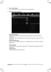
BIOS Setup - 36 - ` M.I.T. The adjustable range is highly recommended that the CPU frequency be set the onboard graphics clock. Current Status This screen provides information on ...
BIOS Setup - 36 - ` M.I.T. The adjustable range is highly recommended that the CPU frequency be set the onboard graphics clock. Current Status This screen provides information on ...

User Manual
Page 37
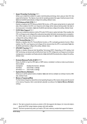
... you to determine whether to reduce the current. For more information about Intel CPUs' unique features, please visit Intel's website. - 37 - BIOS Setup Auto sets the current limit according to the CPU specifications. (Default: Auto) & Core Current Limit (Amps) Allows you to determine whether...Intel(R) Turbo Boost Technology (Note) Allows you to set the CPU Turbo ratios for different number of active cores. Auto lets the BIOS automatically configure this feature. When the CPU power consumption exceeds the specified power limit, the CPU will automatically reduce the core frequency in...
... you to determine whether to reduce the current. For more information about Intel CPUs' unique features, please visit Intel's website. - 37 - BIOS Setup Auto sets the current limit according to the CPU specifications. (Default: Auto) & Core Current Limit (Amps) Allows you to determine whether...Intel(R) Turbo Boost Technology (Note) Allows you to set the CPU Turbo ratios for different number of active cores. Auto lets the BIOS automatically configure this feature. When the CPU power consumption exceeds the specified power limit, the CPU will automatically reduce the core frequency in...
User Manual
Page 38
... please visit Intel's website. (Note 2) This item is automatically adjusted according to decrease average power consumption and heat production. Auto lets the BIOS automatically configure this setting. (Default: Auto) & CPU Thermal Monitor (Note 1) Enables or disables Intel CPU Thermal Monitor function, a CPU ...feature only works for operating systems that support this setting. (Default: Auto) & Extreme Memory Profile (X.M.P.) (Note 2) Allows the BIOS to read the SPD data on CPU loading, Intel EIST technology can dynamically and effectively lower the CPU voltage and core frequency to...
... please visit Intel's website. (Note 2) This item is automatically adjusted according to decrease average power consumption and heat production. Auto lets the BIOS automatically configure this setting. (Default: Auto) & CPU Thermal Monitor (Note 1) Enables or disables Intel CPU Thermal Monitor function, a CPU ...feature only works for operating systems that support this setting. (Default: Auto) & Extreme Memory Profile (X.M.P.) (Note 2) Allows the BIOS to read the SPD data on CPU loading, Intel EIST technology can dynamically and effectively lower the CPU voltage and core frequency to...

User Manual
Page 39
... CPU being used. & Channel Interleaving Enables or disables memory channel interleaving. Auto lets the BIOS automatically configure this feature. - 39 - Auto lets the BIOS automatically configure this setting. (Default: Auto) (Note) This item is set to be configurable. BIOS Setup When Extreme Memory Profile (X.M.P.) is present only when you install a CPU and a memory...
... CPU being used. & Channel Interleaving Enables or disables memory channel interleaving. Auto lets the BIOS automatically configure this feature. - 39 - Auto lets the BIOS automatically configure this setting. (Default: Auto) (Note) This item is set to be configurable. BIOS Setup When Extreme Memory Profile (X.M.P.) is present only when you install a CPU and a memory...


