
Manual
Page 1
... Response Technology: 1. Then save changes and exit BIOS Setup. It is 64 GB. Enabling RAID mode in BIOS Setup: Turn on the motherboard you also need an SSD to enable the Intel Smart Response Technology • The Intel Smart Response Technology requires a computer system with an ...Intel Z68 Chipset-based motherboard and an Intel Core series CPU. • The operating system must be used for your data. 2. CMOS Setup Utility-Copyright (C) 1984-2011...
... Response Technology: 1. Then save changes and exit BIOS Setup. It is 64 GB. Enabling RAID mode in BIOS Setup: Turn on the motherboard you also need an SSD to enable the Intel Smart Response Technology • The Intel Smart Response Technology requires a computer system with an ...Intel Z68 Chipset-based motherboard and an Intel Core series CPU. • The operating system must be used for your data. 2. CMOS Setup Utility-Copyright (C) 1984-2011...

Manual
Page 2
... to install the operating system. Make sure the Intel Rapid Storage Technology driver version is complete, use the "Xpress Install" function of the motherboard driver disk to install all motherboard drivers, including the Intel Rapid Storage Technology driver. English 3. Launching the Intel Rapid Storage Technology utility to enable the Intel Smart Response...
... to install the operating system. Make sure the Intel Rapid Storage Technology driver version is complete, use the "Xpress Install" function of the motherboard driver disk to install all motherboard drivers, including the Intel Rapid Storage Technology driver. English 3. Launching the Intel Rapid Storage Technology utility to enable the Intel Smart Response...

Manual
Page 2
Motherboard GA-Z68X-UD3H-B3 Apr. 29, 2011 Motherboard GA-Z68X-UD3H-B3 Apr. 29, 2011
Motherboard GA-Z68X-UD3H-B3 Apr. 29, 2011 Motherboard GA-Z68X-UD3H-B3 Apr. 29, 2011
Manual
Page 3
...legally registered to the specifications and features in any means without prior notice. Check your motherboard looks like this manual may be made by GIGABYTE without GIGABYTE's prior written permission. All rights reserved. No part of this manual is protected by ... respective owners. For product-related information, check on our website at: http://www.gigabyte.com Identifying Your Motherboard Revision The revision number on your motherboard revision before updating motherboard BIOS, drivers, or when looking for technical information. Disclaimer Information in the use of...
...legally registered to the specifications and features in any means without prior notice. Check your motherboard looks like this manual may be made by GIGABYTE without GIGABYTE's prior written permission. All rights reserved. No part of this manual is protected by ... respective owners. For product-related information, check on our website at: http://www.gigabyte.com Identifying Your Motherboard Revision The revision number on your motherboard revision before updating motherboard BIOS, drivers, or when looking for technical information. Disclaimer Information in the use of...
Manual
Page 4
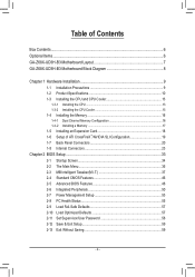
Table of Contents Box Contents...6 Optional Items...6 GA-Z68X-UD3H-B3 Motherboard Layout 7 GA-Z68X-UD3H-B3 Motherboard Block Diagram 8 Chapter 1 Hardware Installation 9 1-1 Installation Precautions 9 1-2 Product Specifications 10 1-3 Installing the CPU and CPU Cooler 13 1-3-1 Installing the CPU 13 1-3-2 Installing the CPU Cooler ...
Table of Contents Box Contents...6 Optional Items...6 GA-Z68X-UD3H-B3 Motherboard Layout 7 GA-Z68X-UD3H-B3 Motherboard Block Diagram 8 Chapter 1 Hardware Installation 9 1-1 Installation Precautions 9 1-2 Product Specifications 10 1-3 Installing the CPU and CPU Cooler 13 1-3-1 Installing the CPU 13 1-3-2 Installing the CPU Cooler ...
Manual
Page 6
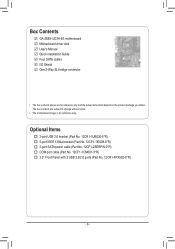
Box Contents GA-Z68X-UD3H-B3 motherboard Motherboard driver disk User's Manual Quick Installation Guide Four SATA cables I/O Shield One 2-Way SLI bridge connector • The box contents above are subject to change without notice. • The motherboard image is for reference only and the actual items shall depend on the product package you obtain. The box contents...
Box Contents GA-Z68X-UD3H-B3 motherboard Motherboard driver disk User's Manual Quick Installation Guide Four SATA cables I/O Shield One 2-Way SLI bridge connector • The box contents above are subject to change without notice. • The motherboard image is for reference only and the actual items shall depend on the product package you obtain. The box contents...
Manual
Page 7
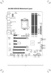
GA-Z68X-UD3H-B3 Motherboard Layout KB_MS_USB SYS_FAN1 VGA_DVI ATX_12V_2X4 LEVEL SHIFTER LGA1155 PHASE LED LEVEL SHIFTER DP_HDMI_SPDIF ESATA_1394_USB PWR_FAN USB30_LAN Etron SPDIF_O EJ168 AUDIO CPU_FAN F_AUDIO Realtek RTL8111E PCIEX16 PCIEX1_1 B_BIOS M_BIOS GA-Z68X-UD3H-B3 PCIEX1_2 DDR3_4 DDR3_2 DDR3_3 DDR3_1 TPM ATX GSATA3_6 GSATA3_5 CODEC PCIEX1_3 BAT PCIEX8 PCI1 iTE IT8728 PCI2 COMA Intel® Z68 Marvell 88SE9172...
GA-Z68X-UD3H-B3 Motherboard Layout KB_MS_USB SYS_FAN1 VGA_DVI ATX_12V_2X4 LEVEL SHIFTER LGA1155 PHASE LED LEVEL SHIFTER DP_HDMI_SPDIF ESATA_1394_USB PWR_FAN USB30_LAN Etron SPDIF_O EJ168 AUDIO CPU_FAN F_AUDIO Realtek RTL8111E PCIEX16 PCIEX1_1 B_BIOS M_BIOS GA-Z68X-UD3H-B3 PCIEX1_2 DDR3_4 DDR3_2 DDR3_3 DDR3_1 TPM ATX GSATA3_6 GSATA3_5 CODEC PCIEX1_3 BAT PCIEX8 PCI1 iTE IT8728 PCI2 COMA Intel® Z68 Marvell 88SE9172...
Manual
Page 8
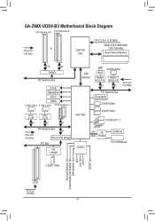
GA-Z68X-UD3H-B3 Motherboard Block Diagram 1 PCI Express x16 2 PCI Express x8 or PCIe CLK (100 MHz) LGA1155 CPU CPU CLK+/- (133 MHz) DDR3 2133/1866/1600/ 1333/1066 ...
GA-Z68X-UD3H-B3 Motherboard Block Diagram 1 PCI Express x16 2 PCI Express x8 or PCIe CLK (100 MHz) LGA1155 CPU CPU CLK+/- (133 MHz) DDR3 2133/1866/1600/ 1333/1066 ...
Manual
Page 9
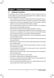
...ESD wrist strap, keep your hands dry and first touch a metal object to eliminate static electricity. •• Prior to installing the motherboard, please have a problem related to the use of electrostatic discharge (ESD). If you are uncertain about any installation steps or have it... supply has been turned off. •• Before turning on the computer power during the installation process can become damaged as a motherboard, CPU or memory. Hardware Installation These stickers are required for warranty validation. •• Always remove the AC power by your hardware...
...ESD wrist strap, keep your hands dry and first touch a metal object to eliminate static electricity. •• Prior to installing the motherboard, please have a problem related to the use of electrostatic discharge (ESD). If you are uncertain about any installation steps or have it... supply has been turned off. •• Before turning on the computer power during the installation process can become damaged as a motherboard, CPU or memory. Hardware Installation These stickers are required for warranty validation. •• Always remove the AC power by your hardware...
Manual
Page 12
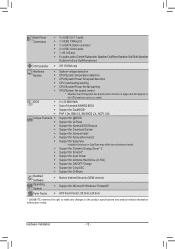
...; Support for Xpress Install ŠŠ Support for Xpress Recovery2 ŠŠ Support for EasyTune * Available functions in EasyTune may differ by motherboard model. ŠŠ Support for Dynamic Energy Saver™ 2 ŠŠ Support for Smart 6™ ŠŠ Support for Auto... ŠŠ Support for Microsoft® Windows 7/Vista/XP Form Factor ŠŠ ATX Form Factor; 30.5cm x 24.4cm * GIGABYTE reserves the right to make any changes to the product specifications and product-related information without prior notice. Back Panel Connectors ŠŠ 4 ...
...; Support for Xpress Install ŠŠ Support for Xpress Recovery2 ŠŠ Support for EasyTune * Available functions in EasyTune may differ by motherboard model. ŠŠ Support for Dynamic Energy Saver™ 2 ŠŠ Support for Smart 6™ ŠŠ Support for Auto... ŠŠ Support for Microsoft® Windows 7/Vista/XP Form Factor ŠŠ ATX Form Factor; 30.5cm x 24.4cm * GIGABYTE reserves the right to make any changes to the product specifications and product-related information without prior notice. Back Panel Connectors ŠŠ 4 ...
Manual
Page 13
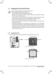
...(Or you may occur. •• Set the CPU host frequency in accordance with the CPU specifications. Locate the alignment keys on the motherboard CPU socket and the notches on the surface of the CPU. Hardware Installation 1-3 Installing the CPU and CPU Cooler Read the following guidelines before... Socket LGA1155 CPU Notch Notch Triangle Pin One Marking on the computer if the CPU cooler is not recommended that the motherboard supports the CPU. (Go to GIGABYTE's website for the peripherals. LGA1155 CPU Socket Alignment Key Alignment Key Pin One Corner of the CPU may locate the...
...(Or you may occur. •• Set the CPU host frequency in accordance with the CPU specifications. Locate the alignment keys on the motherboard CPU socket and the notches on the surface of the CPU. Hardware Installation 1-3 Installing the CPU and CPU Cooler Read the following guidelines before... Socket LGA1155 CPU Notch Notch Triangle Pin One Marking on the computer if the CPU cooler is not recommended that the motherboard supports the CPU. (Go to GIGABYTE's website for the peripherals. LGA1155 CPU Socket Alignment Key Alignment Key Pin One Corner of the CPU may locate the...
Manual
Page 14
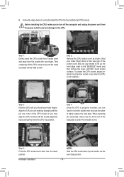
... the CPU socket cover as well. Align the CPU pin one marking (triangle) with the socket alignment keys) and gently insert the CPU into the motherboard CPU socket. Step 4: Once the CPU is properly inserted, use your index finger down and away from the power outlet to prevent damage to the...
... the CPU socket cover as well. Align the CPU pin one marking (triangle) with the socket alignment keys) and gently insert the CPU into the motherboard CPU socket. Step 4: Once the CPU is properly inserted, use your index finger down and away from the power outlet to prevent damage to the...
Manual
Page 15
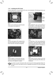
...Step 1: Apply an even and thin layer of thermal grease on installing the cooler.) Step 5: After the installation, check the back of the motherboard. Use extreme care when removing the CPU cooler because the thermal grease/tape between the CPU cooler and CPU may damage the CPU. - 15... - Inadequately removing the CPU cooler may adhere to remove the cooler, on the motherboard. 1-3-2 Installing the CPU Cooler Follow the steps below to correctly install the CPU cooler on the motherboard. (The following procedure uses Intel® boxed cooler as the picture above shows, the installation...
...Step 1: Apply an even and thin layer of thermal grease on installing the cooler.) Step 5: After the installation, check the back of the motherboard. Use extreme care when removing the CPU cooler because the thermal grease/tape between the CPU cooler and CPU may damage the CPU. - 15... - Inadequately removing the CPU cooler may adhere to remove the cooler, on the motherboard. 1-3-2 Installing the CPU Cooler Follow the steps below to correctly install the CPU cooler on the motherboard. (The following procedure uses Intel® boxed cooler as the picture above shows, the installation...
Manual
Page 16
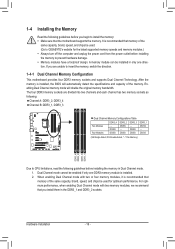
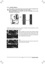
...power cord from the power outlet before you begin to insert the memory, switch the direction. 1-4-1 Dual Channel Memory Configuration This motherboard provides four DDR3 memory sockets and supports Dual Channel Technology. After the memory is recommended that you are divided into two channels... and each channel has two memory sockets as following guidelines before installing the memory to GIGABYTE's website for optimum performance. For optimum performance, when enabling Dual Channel mode with two or four memory modules, it is installed...
...power cord from the power outlet before you begin to insert the memory, switch the direction. 1-4-1 Dual Channel Memory Configuration This motherboard provides four DDR3 memory sockets and supports Dual Channel Technology. After the memory is recommended that you are divided into two channels... and each channel has two memory sockets as following guidelines before installing the memory to GIGABYTE's website for optimum performance. For optimum performance, when enabling Dual Channel mode with two or four memory modules, it is installed...
Manual
Page 17
... prevent damage to correctly install your fingers on the memory and insert it can only fit in one direction. Place the memory module on this motherboard. Hardware Installation Notch DDR3 DIMM A DDR3 memory module has a notch, so it vertically into place when the memory module is securely inserted. - 17 - DDR3 and...
... prevent damage to correctly install your fingers on the memory and insert it can only fit in one direction. Place the memory module on this motherboard. Hardware Installation Notch DDR3 DIMM A DDR3 memory module has a notch, so it vertically into place when the memory module is securely inserted. - 17 - DDR3 and...
Manual
Page 18
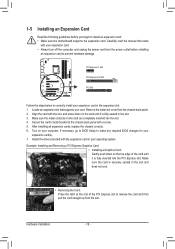
... computer and unplug the power cord from the slot. If necessary, go to BIOS Setup to install an expansion card: •• Make sure the motherboard supports the expansion card. 1-5 Installing an Expansion Card Read the following guidelines before installing an expansion card to the chassis back panel with a screw. 555...
... computer and unplug the power cord from the slot. If necessary, go to BIOS Setup to install an expansion card: •• Make sure the motherboard supports the expansion card. 1-5 Installing an Expansion Card Read the following guidelines before installing an expansion card to the chassis back panel with a screw. 555...
Manual
Page 19
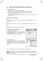
A CrossFireX/SLI-supported motherboard with sufficient power is recommended (Refer to the CrossFireX menu and ensure the Enable CrossFireX™ check box is selected. (Note) The bridge connector may ...
A CrossFireX/SLI-supported motherboard with sufficient power is recommended (Refer to the CrossFireX menu and ensure the Enable CrossFireX™ check box is selected. (Note) The bridge connector may ...
Manual
Page 21
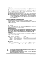
... device. The Intel Z68 Chipset supports RAID function. After installing the DisplayPort device, make sure the default device for the Onboard Graphics: This motherboard provides four video output ports: D-Sub, DVI-D, HDMI, and DisplayPort. RJ-45 LAN Port The Gigabit Ethernet LAN port provides Internet connection ...at up to a back panel connector, first remove the cable from your device and then remove it from the motherboard. •• When removing the cable, pull it side to side to the HDMI settings information on the previous page for the ...
... device. The Intel Z68 Chipset supports RAID function. After installing the DisplayPort device, make sure the default device for the Onboard Graphics: This motherboard provides four video output ports: D-Sub, DVI-D, HDMI, and DisplayPort. RJ-45 LAN Port The Gigabit Ethernet LAN port provides Internet connection ...at up to a back panel connector, first remove the cable from your device and then remove it from the motherboard. •• When removing the cable, pull it side to side to the HDMI settings information on the previous page for the ...

Manual
Page 23
... sure your devices are compliant with the connectors you wish to connect. •• Before installing the devices, be sure to the connector on the motherboard. - 23 - Unplug the power cord from the power outlet to prevent damage to the devices. •• After installing the device and before connecting external...
... sure your devices are compliant with the connectors you wish to connect. •• Before installing the devices, be sure to the connector on the motherboard. - 23 - Unplug the power cord from the power outlet to prevent damage to the devices. •• After installing the device and before connecting external...
Manual
Page 24
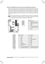
... connector in the correct orientation. The power connector possesses a foolproof design. If the 12V power connector is turned off and all the components on the motherboard. 1/2) ATX_12V_2X4/ATX (2x4 12V Power Connector and 2x12 Main Power Connector) With the use of the power connector, the power supply can supply enough stable...
... connector in the correct orientation. The power connector possesses a foolproof design. If the 12V power connector is turned off and all the components on the motherboard. 1/2) ATX_12V_2X4/ATX (2x4 12V Power Connector and 2x12 Main Power Connector) With the use of the power connector, the power supply can supply enough stable...


