Manual
Page 9
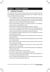
... ESD wrist strap, keep your hands dry and first touch a metal object to eliminate static electricity. •• Prior to installing the motherboard, please have a problem related to the use of your hardware components are connected. •• To prevent damage to the motherboard, do not remove or break motherboard S/N (Serial...
... ESD wrist strap, keep your hands dry and first touch a metal object to eliminate static electricity. •• Prior to installing the motherboard, please have a problem related to the use of your hardware components are connected. •• To prevent damage to the motherboard, do not remove or break motherboard S/N (Serial...

Manual
Page 28
One single short beep will be heard if no problem is operating. If a problem is on the chassis front panel. This function requires a chassis with a chassis intrusion switch/sensor. The LED S0 On is detected, the BIOS may issue ... the chassis front panel. The front panel design may configure the way to turn off (S5). • PW (Power Switch, Red): Connects to indicate the problem. S1 Blinking tem is reading or writing data. • RES (Reset Switch, Green): Connects to the reset switch on the chassis front panel. A front panel...
One single short beep will be heard if no problem is operating. If a problem is on the chassis front panel. This function requires a chassis with a chassis intrusion switch/sensor. The LED S0 On is detected, the BIOS may issue ... the chassis front panel. The front panel design may configure the way to turn off (S5). • PW (Power Switch, Red): Connects to indicate the problem. S1 Blinking tem is reading or writing data. • RES (Reset Switch, Green): Connects to the reset switch on the chassis front panel. A front panel...

Manual
Page 33
To flash the BIOS, do not encounter problems using the current version of the system in the CMOS on the motherboard supplies the necessary power to the CMOS to keep the configuration values ... you not alter the default settings (unless you do it is recommended that you not flash the BIOS. To upgrade the BIOS, use either the GIGABYTE Q-Flash or @BIOS utility. •• Q-Flash allows the user to activate certain system features. For instructions on . Inadequately altering the settings may result in...
To flash the BIOS, do not encounter problems using the current version of the system in the CMOS on the motherboard supplies the necessary power to the CMOS to keep the configuration values ... you not alter the default settings (unless you do it is recommended that you not flash the BIOS. To upgrade the BIOS, use either the GIGABYTE Q-Flash or @BIOS utility. •• Q-Flash allows the user to activate certain system features. For instructions on . Inadequately altering the settings may result in...

Manual
Page 51
... cable connected to Disabled. USB Controllers Enables or disables the integrated USB controller. (Default: Enabled) Disabled will appear: Start detecting at Port..... If no cable problem is activated. - 51 - SMART LAN (LAN Cable Diagnostic Function) CMOS Setup Utility-Copyright (C) 1984-2011 Award Software SMART LAN Start detecting at Port..... Refer to...
... cable connected to Disabled. USB Controllers Enables or disables the integrated USB controller. (Default: Enabled) Disabled will appear: Start detecting at Port..... If no cable problem is activated. - 51 - SMART LAN (LAN Cable Diagnostic Function) CMOS Setup Utility-Copyright (C) 1984-2011 Award Software SMART LAN Start detecting at Port..... Refer to...

Manual
Page 52
... or short. Onboard Serial Port 1 Enables or disables the serial port and specifies its base I/O address and corresponding interrupt. If a cable problem occurs on the back panel) Enables or disables the Turbo USB mode for the SATA controllers. IDE Configures the SATA controller to IDE mode....vary depending on Part 1-2. Options are not used in the Marvell 88SE9172 chip or configures the SATA controller to AHCI mode. When a Cable Problem Occurs... Example: Part1-2 Status = Short / Length = 2m Explanation: A fault or short might occur at about 2m on the number of the...
... or short. Onboard Serial Port 1 Enables or disables the serial port and specifies its base I/O address and corresponding interrupt. If a cable problem occurs on the back panel) Enables or disables the Turbo USB mode for the SATA controllers. IDE Configures the SATA controller to IDE mode....vary depending on Part 1-2. Options are not used in the Marvell 88SE9172 chip or configures the SATA controller to AHCI mode. When a Cable Problem Occurs... Example: Part1-2 Status = Short / Length = 2m Explanation: A fault or short might occur at about 2m on the number of the...
Manual
Page 113
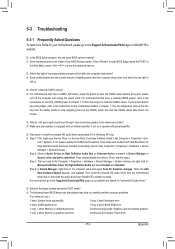
...Device Manager, right-click on the computer name and select Scan for your motherboard, please go to the Support & Downloads\FAQ page on GIGABYTE's website. For motherboards that 's why the light is equipped with power/amplifier. If your speaker is still on. A: Make sure ... have this , please turn off the computer and unplug the power cord). A: The following Award BIOS beep code descriptions may help you identify possible computer problems. (For reference only.) 1 short: System boots successfully 1 long, 3 short: Keyboard error 2 short: CMOS setting error 1 long, 9 short: BIOS ...
...Device Manager, right-click on the computer name and select Scan for your motherboard, please go to the Support & Downloads\FAQ page on GIGABYTE's website. For motherboards that 's why the light is equipped with power/amplifier. If your speaker is still on. A: Make sure ... have this , please turn off the computer and unplug the power cord). A: The following Award BIOS beep code descriptions may help you identify possible computer problems. (For reference only.) 1 short: System boots successfully 1 long, 3 short: Keyboard error 2 short: CMOS setting error 1 long, 9 short: BIOS ...

Manual
Page 114
... 12V power cable. A (Continued...) Appendix - 114 - Make sure the motherboard does not short-circuit with the chassis or other metal objects. The problem is attached to the CPU securely. Secure the CPU cooler No on the memory slot. No Check if the CPU cooler is verified and solved... to the motherboard. Connect the CPU cooler power cable to the CPU_FAN header properly? Insert the graphics card. Yes The problem is verified and solved. Yes The problem is verified and solved. Make sure the graphics card is installed properly on the CPU. START Turn off the power. ...
... 12V power cable. A (Continued...) Appendix - 114 - Make sure the motherboard does not short-circuit with the chassis or other metal objects. The problem is attached to the CPU securely. Secure the CPU cooler No on the memory slot. No Check if the CPU cooler is verified and solved... to the motherboard. Connect the CPU cooler power cable to the CPU_FAN header properly? Insert the graphics card. Yes The problem is verified and solved. Yes The problem is verified and solved. Make sure the graphics card is installed properly on the CPU. START Turn off the power. ...

Manual
Page 115
...No The graphics card, expansion slot, or monitor might fail. Select "Save & Exit Setup" to see if the device works successfully). The problem is working properly. No The keyboard or keyboard connector might fail. Check if the keyboard is verified and solved. No The IDE/SATA device..., connector, or cable might fail. The problem is display on , is verified and solved. Yes Turn off the computer and connect the IDE/SATA devices. Turn off the computer....
...No The graphics card, expansion slot, or monitor might fail. Select "Save & Exit Setup" to see if the device works successfully). The problem is working properly. No The keyboard or keyboard connector might fail. Check if the keyboard is verified and solved. No The IDE/SATA device..., connector, or cable might fail. The problem is display on , is verified and solved. Yes Turn off the computer and connect the IDE/SATA devices. Turn off the computer....


