
Manual
Page 1
... F5: Previous Values +/-/PU/PD: Value F10: Save F6: Fail-Safe Defaults ESC: Exit F1: General Help F7: Optimized Defaults The BIOS Setup menus described here may differ from the exact settings for storing your motherboard. Installing a conventional SATA hard disk and a solid-state drive...the steps below to the SATA disk. • Supported operating systems include Windows 7 and Windows Vista. • If you have and the BIOS version. - 1 - Launching the Intel Rapid Storage Technology utility to enable the Intel Smart Response Technology • The Intel Smart Response Technology...
... F5: Previous Values +/-/PU/PD: Value F10: Save F6: Fail-Safe Defaults ESC: Exit F1: General Help F7: Optimized Defaults The BIOS Setup menus described here may differ from the exact settings for storing your motherboard. Installing a conventional SATA hard disk and a solid-state drive...the steps below to the SATA disk. • Supported operating systems include Windows 7 and Windows Vista. • If you have and the BIOS version. - 1 - Launching the Intel Rapid Storage Technology utility to enable the Intel Smart Response Technology • The Intel Smart Response Technology...

Manual
Page 2
... to install all motherboard drivers, including the Intel Rapid Storage Technology driver. Installing the operating system and drivers to the SATA disk: After setting the BIOS, you can begin to open the Intel Rapid Storage Technology utility. - 2 - After the installation is 10.5 or above and restarting your system, find the...
... to install all motherboard drivers, including the Intel Rapid Storage Technology driver. Installing the operating system and drivers to the SATA disk: After setting the BIOS, you can begin to open the Intel Rapid Storage Technology utility. - 2 - After the installation is 10.5 or above and restarting your system, find the...

Manual
Page 3
... mentioned in this manual may be reproduced, copied, translated, transmitted, or published in this manual may be made by GIGABYTE without GIGABYTE's prior written permission. All rights reserved. No part of the product, read the Quick Installation Guide included with the ...is 1.0. For product-related information, check on our website at: http://www.gigabyte.com Identifying Your Motherboard Revision The revision number on your motherboard revision before updating motherboard BIOS, drivers, or when looking for technical information. Example: Documentation Classifications In ...
... mentioned in this manual may be reproduced, copied, translated, transmitted, or published in this manual may be made by GIGABYTE without GIGABYTE's prior written permission. All rights reserved. No part of the product, read the Quick Installation Guide included with the ...is 1.0. For product-related information, check on our website at: http://www.gigabyte.com Identifying Your Motherboard Revision The revision number on your motherboard revision before updating motherboard BIOS, drivers, or when looking for technical information. Example: Documentation Classifications In ...
Manual
Page 4
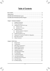
Table of Contents Box Contents...6 Optional Items...6 GA-Z68X-UD3-B3 Motherboard Layout 7 GA-Z68X-UD3-B3 Motherboard Block Diagram 8 Chapter 1 Hardware Installation 9 1-1 Installation Precautions 9 1-2 Product Specifications 10 1-3 Installing the CPU and CPU Cooler ... SLI Configuration 19 1-7 Back Panel Connectors 20 1-8 Internal Connectors 22 Chapter 2 BIOS Setup 33 2-1 Startup Screen 34 2-2 The Main Menu 35 2-3 MB Intelligent Tweaker(M.I.T 37 2-4 Standard CMOS Features 45 2-5 Advanced BIOS Features 47 2-6 Integrated Peripherals 49 2-7 Power Management Setup 52 2-8 PC Health ...
Table of Contents Box Contents...6 Optional Items...6 GA-Z68X-UD3-B3 Motherboard Layout 7 GA-Z68X-UD3-B3 Motherboard Block Diagram 8 Chapter 1 Hardware Installation 9 1-1 Installation Precautions 9 1-2 Product Specifications 10 1-3 Installing the CPU and CPU Cooler ... SLI Configuration 19 1-7 Back Panel Connectors 20 1-8 Internal Connectors 22 Chapter 2 BIOS Setup 33 2-1 Startup Screen 34 2-2 The Main Menu 35 2-3 MB Intelligent Tweaker(M.I.T 37 2-4 Standard CMOS Features 45 2-5 Advanced BIOS Features 47 2-6 Integrated Peripherals 49 2-7 Power Management Setup 52 2-8 PC Health ...

Manual
Page 5
... 60 3-4 Contact...61 3-5 System...61 3-6 Download Center 62 3-7 New Utilities...62 Chapter 4 Unique Features 63 4-1 Xpress Recovery2 63 4-2 BIOS Update Utilities 66 4-2-1 Updating the BIOS with the Q-Flash Utility 66 4-2-2 Updating the BIOS with the @BIOS Utility 69 4-3 EasyTune 6...70 4-4 Dynamic Energy Saver™ 2 71 4-5 Q-Share...73 4-6 Smart 6™ ...74 4-7 Auto Green...78 4-8 eXtreme...
... 60 3-4 Contact...61 3-5 System...61 3-6 Download Center 62 3-7 New Utilities...62 Chapter 4 Unique Features 63 4-1 Xpress Recovery2 63 4-2 BIOS Update Utilities 66 4-2-1 Updating the BIOS with the Q-Flash Utility 66 4-2-2 Updating the BIOS with the @BIOS Utility 69 4-3 EasyTune 6...70 4-4 Dynamic Energy Saver™ 2 71 4-5 Q-Share...73 4-6 Smart 6™ ...74 4-7 Auto Green...78 4-8 eXtreme...

Manual
Page 8
GA-Z68X-UD3-B3 Motherboard Block Diagram PCIe CLK (100 MHz) 1 PCI Express x16 or 2 PCI Express x8 LGA1155 CPU CPU CLK+/- (100 MHz) DDR3 2133/1866/1600/1333/... to PCI Bridge Intel® Z68 PCI Bus VIA VT6308 CODEC 2 IEEE 1394a 2 USB 3.0/2.0 2 USB 3.0/2.0 Etron EJ168 Etron EJ168 x1 x1 PCI Express Bus Dual BIOS 4 SATA 3Gb/s 2 SATA 6Gb/s 14 USB 2.0/1.1 LPC Bus iTE IT8728 COM Port PS/2 KB/Mouse Surround Speaker Out Center/Subwoofer Speaker Out Side Speaker Out...
GA-Z68X-UD3-B3 Motherboard Block Diagram PCIe CLK (100 MHz) 1 PCI Express x16 or 2 PCI Express x8 LGA1155 CPU CPU CLK+/- (100 MHz) DDR3 2133/1866/1600/1333/... to PCI Bridge Intel® Z68 PCI Bus VIA VT6308 CODEC 2 IEEE 1394a 2 USB 3.0/2.0 2 USB 3.0/2.0 Etron EJ168 Etron EJ168 x1 x1 PCI Express Bus Dual BIOS 4 SATA 3Gb/s 2 SATA 6Gb/s 14 USB 2.0/1.1 LPC Bus iTE IT8728 COM Port PS/2 KB/Mouse Surround Speaker Out Center/Subwoofer Speaker Out Side Speaker Out...

Manual
Page 12
...flash ŠŠ Use of licensed AWARD BIOS ŠŠ Support for DualBIOS™ ŠŠ PnP 1.0a, DMI 2.0, SM BIOS 2.4, ACPI 1.0b Unique Features ŠŠ Support for @BIOS ŠŠ Support for Q-Flash ŠŠ Support for Xpress BIOS Rescue ŠŠ Support for Download Center...;Š Support for Microsoft® Windows 7/Vista/XP Form Factor ŠŠ ATX Form Factor; 30.5cm x 24.4cm * GIGABYTE reserves the right to make any changes to the product specifications and product-related information without prior notice. Hardware ŠŠ System voltage...
...flash ŠŠ Use of licensed AWARD BIOS ŠŠ Support for DualBIOS™ ŠŠ PnP 1.0a, DMI 2.0, SM BIOS 2.4, ACPI 1.0b Unique Features ŠŠ Support for @BIOS ŠŠ Support for Q-Flash ŠŠ Support for Xpress BIOS Rescue ŠŠ Support for Download Center...;Š Support for Microsoft® Windows 7/Vista/XP Form Factor ŠŠ ATX Form Factor; 30.5cm x 24.4cm * GIGABYTE reserves the right to make any changes to the product specifications and product-related information without prior notice. Hardware ŠŠ System voltage...

Manual
Page 16
...recommended that you install them in Dual Channel mode. 1. DS/SS DS/SS DDR3_2 DS/SS - DS/SS DDR3_3 - It is installed, the BIOS will double the original memory bandwidth. DS/SS (SS=Single-Sided, DS=Double-Sided, "- -"=No Memory) DDR3_4 DDR3_2 DDR3_3 DDR3_1 Due to ...speed, and chips be enabled if only one direction. DS/SS DS/SS DDR3_1 DS/SS - Dual Channel mode cannot be used . (Go to GIGABYTE's website for optimum performance. 1-4 Installing the Memory Read the following guidelines before you begin to prevent hardware damage. •• Memory modules have a...
...recommended that you install them in Dual Channel mode. 1. DS/SS DS/SS DDR3_2 DS/SS - DS/SS DDR3_3 - It is installed, the BIOS will double the original memory bandwidth. DS/SS (SS=Single-Sided, DS=Double-Sided, "- -"=No Memory) DDR3_4 DDR3_2 DDR3_3 DDR3_1 Due to ...speed, and chips be enabled if only one direction. DS/SS DS/SS DDR3_1 DS/SS - Dual Channel mode cannot be used . (Go to GIGABYTE's website for optimum performance. 1-4 Installing the Memory Read the following guidelines before you begin to prevent hardware damage. •• Memory modules have a...

Manual
Page 18
... back panel. 222 Align the card with your computer. Make sure the card is securely seated in your card. If necessary, go to BIOS Setup to make any required BIOS changes for your expansion card(s). 777 Install the driver provided with a screw. 555 After installing all expansion cards, replace the chassis cover...
... back panel. 222 Align the card with your computer. Make sure the card is securely seated in your card. If necessary, go to BIOS Setup to make any required BIOS changes for your expansion card(s). 777 Install the driver provided with a screw. 555 After installing all expansion cards, replace the chassis cover...

Manual
Page 24
... design. Definition 1 1 SYS_FAN1 PWR_FAN 1 GND 2 +12V 3 Sense •• Be sure to connect fan cables to the fan headers to keep the values (such as BIOS configurations, date, and time information) in the correct orientation (the black connector wire is replaced with an equivalent one minute. (Or use of purchase or...
... design. Definition 1 1 SYS_FAN1 PWR_FAN 1 GND 2 +12V 3 Sense •• Be sure to connect fan cables to the fan headers to keep the values (such as BIOS configurations, date, and time information) in the correct orientation (the black connector wire is replaced with an equivalent one minute. (Or use of purchase or...

Manual
Page 27
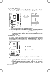
...pin assignments below. The LED is on when the hard drive is operating. When connecting your system using the power switch (refer to Chapter 2, "BIOS Setup," "Power Management Setup," for information about beep codes. •• HD (Hard Drive Activity LED, Blue) Connects to the power status ... when the sys- If a problem is in S3/S4 sleep S3/S4/S5 Off state or powered off when the system is detected, the BIOS may differ by issuing a beep code. Hardware Installation Note the positive and negative pins before connecting the cables. Refer to Chapter 5, "Troubleshooting,"...
...pin assignments below. The LED is on when the hard drive is operating. When connecting your system using the power switch (refer to Chapter 2, "BIOS Setup," "Power Management Setup," for information about beep codes. •• HD (Hard Drive Activity LED, Blue) Connects to the power status ... when the sys- If a problem is in S3/S4 sleep S3/S4/S5 Off state or powered off when the system is detected, the BIOS may differ by issuing a beep code. Hardware Installation Note the positive and negative pins before connecting the cables. Refer to Chapter 5, "Troubleshooting,"...
Manual
Page 30
...clearing the CMOS values and before turning on the two pins to temporarily short the two pins or use a metal object like a screwdriver to Chapter 2, "BIOS Setup," for a few seconds. Pin No. Ensure that the cable is securely connected. 17) CLR_CMOS (Clearing CMOS Jumper) Use this jumper to remove ...into the IEEE 1394a header. • Prior to installing the IEEE 1394a bracket, be sure to clear the CMOS values (e.g. date information and BIOS configurations) and reset the CMOS values to the IEEE 1394a device. 16) F_1394 (IEEE 1394a Header) The header conforms to IEEE 1394a specification.
...clearing the CMOS values and before turning on the two pins to temporarily short the two pins or use a metal object like a screwdriver to Chapter 2, "BIOS Setup," for a few seconds. Pin No. Ensure that the cable is securely connected. 17) CLR_CMOS (Clearing CMOS Jumper) Use this jumper to remove ...into the IEEE 1394a header. • Prior to installing the IEEE 1394a bracket, be sure to clear the CMOS values (e.g. date information and BIOS configurations) and reset the CMOS values to the IEEE 1394a device. 16) F_1394 (IEEE 1394a Header) The header conforms to IEEE 1394a specification.

Manual
Page 33
... press + in system's failure to boot. To see more advanced BIOS Setup menu options, you need to) to prevent system instability or other unexpected results. To upgrade the BIOS, use either the GIGABYTE Q-Flash or @BIOS utility. • Q-Flash allows the user to quickly and easily upgrade... or back up BIOS without entering the operating system. • @BIOS is turned on using the current version of BIOS, it with caution. Inadequate BIOS flashing may result ...
... press + in system's failure to boot. To see more advanced BIOS Setup menu options, you need to) to prevent system instability or other unexpected results. To upgrade the BIOS, use either the GIGABYTE Q-Flash or @BIOS utility. • Q-Flash allows the user to quickly and easily upgrade... or back up BIOS without entering the operating system. • @BIOS is turned on using the current version of BIOS, it with caution. Inadequate BIOS flashing may result ...

Manual
Page 34
The LOGO Screen (Default) B. To show the BIOS POST screen. Motherboard Model BIOS Version Z68X-UD3-B3 D5x . . . . : BIOS Setup : XpressRecovery2 : Boot Menu : Qflash 04/12/2011-Z68-7A89WG06C-00 Function Keys Function Keys Function Keys: : POST SCREEN Press the key to show the BIOS POST screen at system startup, refer to the instructions on the Full Screen...
The LOGO Screen (Default) B. To show the BIOS POST screen. Motherboard Model BIOS Version Z68X-UD3-B3 D5x . . . . : BIOS Setup : XpressRecovery2 : Boot Menu : Qflash 04/12/2011-Z68-7A89WG06C-00 Function Keys Function Keys Function Keys: : POST SCREEN Press the key to show the BIOS POST screen at system startup, refer to the instructions on the Full Screen...
Manual
Page 35
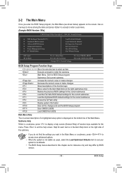
... Help While in a submenu, press to its defaults. • The BIOS Setup menus described in this chapter are for reference only and may differ by BIOS version. - 35 - Press to BIOS Load CMOS from BIOS BIOS Setup Program Function Keys Move the selection bar to select an item Execute command...Without Saving ESC: Quit F8: Q-Flash Select Item F10: Save & Exit Setup Change CPU's Clock & Voltage F11: Save CMOS to BIOS F12: Load CMOS from BIOS Main Menu Help The on-screen description of a highlighted setup option is displayed on the right side of the submenu. • If ...
... Help While in a submenu, press to its defaults. • The BIOS Setup menus described in this chapter are for reference only and may differ by BIOS version. - 35 - Press to BIOS Load CMOS from BIOS BIOS Setup Program Function Keys Move the selection bar to select an item Execute command...Without Saving ESC: Quit F8: Q-Flash Select Item F10: Save & Exit Setup Change CPU's Clock & Voltage F11: Save CMOS to BIOS F12: Load CMOS from BIOS Main Menu Help The on-screen description of a highlighted setup option is displayed on the right side of the submenu. • If ...

Manual
Page 36
...configure the system time and date, hard drive types, and the type of errors that stop the system boot, etc. Advanced BIOS Features Use this menu to configure the device boot order, advanced features available on the CPU, and the primary display adapter. Integrated...optimal-performance system operations. Set Supervisor Password Change, set , or disable password. It allows you to restrict access to the system and BIOS Setup. First select the profile you wish to load, then press to complete. MB Intelligent Tweaker(M.I.T.) Use this menu to configure the...
...configure the system time and date, hard drive types, and the type of errors that stop the system boot, etc. Advanced BIOS Features Use this menu to configure the device boot order, advanced features available on the CPU, and the primary display adapter. Integrated...optimal-performance system operations. Set Supervisor Password Change, set , or disable password. It allows you to restrict access to the system and BIOS Setup. First select the profile you wish to load, then press to complete. MB Intelligent Tweaker(M.I.T.) Use this menu to configure the...
Manual
Page 37
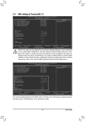
...Miscellaneous Settings [Press Enter] [Press Enter] [Press Enter] [Press Enter] [Press Enter] Item Help Menu Level BIOS Version BCLK CPU Frequency Memory Frequency Total Memory Size CPU Temperature Vcore DRAM Voltage D5x 100.32 MHz 3210.48 MHz 1070.... Settings [Press Enter] [Press Enter] [Press Enter] [Press Enter] [Press Enter] Item Help Menu Level BIOS Version BCLK CPU Frequency Memory Frequency Total Memory Size CPU Temperature Vcore DRAM Voltage D5x 100.32 MHz 3210.48 MHz 1070....
...Miscellaneous Settings [Press Enter] [Press Enter] [Press Enter] [Press Enter] [Press Enter] Item Help Menu Level BIOS Version BCLK CPU Frequency Memory Frequency Total Memory Size CPU Temperature Vcore DRAM Voltage D5x 100.32 MHz 3210.48 MHz 1070.... Settings [Press Enter] [Press Enter] [Press Enter] [Press Enter] [Press Enter] Item Help Menu Level BIOS Version BCLK CPU Frequency Memory Frequency Total Memory Size CPU Temperature Vcore DRAM Voltage D5x 100.32 MHz 3210.48 MHz 1070....
Manual
Page 38
... is present only when you to alter the clock ratio for the installed CPU. Current Status This screen provides information on the CPU being installed. BIOS Setup - 38 - For more information about Intel CPUs' unique features, please visit Intel's website. CPU Frequency Displays the current operating CPU frequency. (Note 1) This item...
... is present only when you to alter the clock ratio for the installed CPU. Current Status This screen provides information on the CPU being installed. BIOS Setup - 38 - For more information about Intel CPUs' unique features, please visit Intel's website. CPU Frequency Displays the current operating CPU frequency. (Note 1) This item...

Manual
Page 39
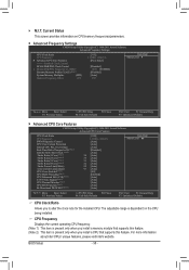
...(C1E) (Note) Enables or disables Intel CPU Enhanced Halt (C1E) function, a CPU power-saving function in system halt state. Auto lets the BIOS automatically configure this setting. (Default: Auto) Turbo Ratio (1-Core)/(2-Core)/(3-Core)/(4-Core) (Note) Allows you to set a power limit for different number... of active cores. All Enables all CPU cores. Auto lets the BIOS automatically configure this feature. Auto sets the power limit according to the CPU specifications. (Default: Auto) Core Current Limit (Amps) Allows you...
...(C1E) (Note) Enables or disables Intel CPU Enhanced Halt (C1E) function, a CPU power-saving function in system halt state. Auto lets the BIOS automatically configure this setting. (Default: Auto) Turbo Ratio (1-Core)/(2-Core)/(3-Core)/(4-Core) (Note) Allows you to set a power limit for different number... of active cores. All Enables all CPU cores. Auto lets the BIOS automatically configure this feature. Auto sets the power limit according to the CPU specifications. (Default: Auto) Core Current Limit (Amps) Allows you...

Manual
Page 40
...you to manually set the system memory multiplier. The C3/C6 state is overheated. Extreme Memory Profile (X.M.P.) (Note 2) Allows the BIOS to read the SPD data on CPU loading, Intel EIST technology can dynamically and effectively lower the CPU voltage and core frequency to ...the CPU base clock and DMI/PCIe bus frequency. Auto lets the BIOS automatically configure this feature. Auto lets the BIOS automatically configure this setting. (Default: Auto) Bi-Directional PROCHOT (Note 1) Auto Lets BIOS automatically configure this setting. (Default) Enabled When the CPU or ...
...you to manually set the system memory multiplier. The C3/C6 state is overheated. Extreme Memory Profile (X.M.P.) (Note 2) Allows the BIOS to read the SPD data on CPU loading, Intel EIST technology can dynamically and effectively lower the CPU voltage and core frequency to ...the CPU base clock and DMI/PCIe bus frequency. Auto lets the BIOS automatically configure this feature. Auto lets the BIOS automatically configure this setting. (Default: Auto) Bi-Directional PROCHOT (Note 1) Auto Lets BIOS automatically configure this setting. (Default) Enabled When the CPU or ...


