
Manual
Page 1
...the X.H.D utiltiy After installing the operating system, insert the motherboard driver disk. Setting Up a RAID-Ready System Step 1: Configure the system BIOS Enter the system BIOS Setup program, set up a RAID array: (Note 3): Click Manual to access the Intel Matrix Storage Console, with a simple click of... damage or lost of a button, X.H.D helps to automatically and quickly set up a RAID 0 array later using the Auto function. Using GIGABYTE eXtreme Hard Drive (X.H.D) Instructions:(Note 2) Before launching X.H.D, make sure the new drive is greater than or equal to enable RAID for RAID ...
...the X.H.D utiltiy After installing the operating system, insert the motherboard driver disk. Setting Up a RAID-Ready System Step 1: Configure the system BIOS Enter the system BIOS Setup program, set up a RAID array: (Note 3): Click Manual to access the Intel Matrix Storage Console, with a simple click of... damage or lost of a button, X.H.D helps to automatically and quickly set up a RAID 0 array later using the Auto function. Using GIGABYTE eXtreme Hard Drive (X.H.D) Instructions:(Note 2) Before launching X.H.D, make sure the new drive is greater than or equal to enable RAID for RAID ...
Manual
Page 3
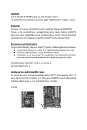
...Downloads\Motherboard\Technology Guide page on our website. For product-related information, check on our website at: http://www.gigabyte.com.tw Identifying Your Motherboard Revision The revision number on how to assist in any form or by copyright laws ...the specifications and features in this manual may be made by GIGABYTE without GIGABYTE's prior written permission. Example: The trademarks mentioned in this : "REV: X.X." For instructions on your motherboard revision before updating motherboard BIOS, drivers, or when looking for technical information. Copyright &#...
...Downloads\Motherboard\Technology Guide page on our website. For product-related information, check on our website at: http://www.gigabyte.com.tw Identifying Your Motherboard Revision The revision number on how to assist in any form or by copyright laws ...the specifications and features in this manual may be made by GIGABYTE without GIGABYTE's prior written permission. Example: The trademarks mentioned in this : "REV: X.X." For instructions on your motherboard revision before updating motherboard BIOS, drivers, or when looking for technical information. Copyright &#...
Manual
Page 4
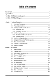
Table of Contents Box Contents...6 Optional Items...6 GA-X58A-UD3R Motherboard Layout 7 GA-X58A-UD3R Block Diagram 8 Chapter 1 Hardware Installation 9 1-1 Installation Precautions 9 1-2 Product Specifications 10 1-3 Installing the CPU and CPU Cooler 13 1-3-1... Panel Connectors 20 1-8 Onboard LEDs and Switches 22 1-9 Internal Connectors 24 Chapter 2 BIOS Setup 35 2-1 Startup Screen 36 2-2 The Main Menu 37 2-3 MB Intelligent Tweaker(M.I.T 39 2-4 Standard CMOS Features 49 2-5 Advanced BIOS Features 51 2-6 Integrated Peripherals 53 2-7 Power Management Setup 57 2-8 PC Health Status...
Table of Contents Box Contents...6 Optional Items...6 GA-X58A-UD3R Motherboard Layout 7 GA-X58A-UD3R Block Diagram 8 Chapter 1 Hardware Installation 9 1-1 Installation Precautions 9 1-2 Product Specifications 10 1-3 Installing the CPU and CPU Cooler 13 1-3-1... Panel Connectors 20 1-8 Onboard LEDs and Switches 22 1-9 Internal Connectors 24 Chapter 2 BIOS Setup 35 2-1 Startup Screen 36 2-2 The Main Menu 37 2-3 MB Intelligent Tweaker(M.I.T 39 2-4 Standard CMOS Features 49 2-5 Advanced BIOS Features 51 2-6 Integrated Peripherals 53 2-7 Power Management Setup 57 2-8 PC Health Status...

Manual
Page 5
... Utilities...68 Chapter 4 Unique Features 69 4-1 Xpress Recovery2 69 4-2 BIOS Update Utilities 72 4-2-1 Updating the BIOS with the Q-Flash Utility 72 4-2-2 Updating the BIOS with the @BIOS Utility 75 4-3 EasyTune 6...76 4-4 Dynamic Energy Saver™ 2... 77 4-5 Q-Share...79 4-6 Smart 6™ ...80 4-7 Auto Green...83 4-8 eXtreme Hard Drive (X.H.D 84 Chapter 5 Appendix...85 5-1 Configuring SATA Hard Drive(s 85 5-1-1 Configuring Intel ICH10R SATA Controllers 85 5-1-2 Configuring JMicron JMB362/GIGABYTE...
... Utilities...68 Chapter 4 Unique Features 69 4-1 Xpress Recovery2 69 4-2 BIOS Update Utilities 72 4-2-1 Updating the BIOS with the Q-Flash Utility 72 4-2-2 Updating the BIOS with the @BIOS Utility 75 4-3 EasyTune 6...76 4-4 Dynamic Energy Saver™ 2... 77 4-5 Q-Share...79 4-6 Smart 6™ ...80 4-7 Auto Green...83 4-8 eXtreme Hard Drive (X.H.D 84 Chapter 5 Appendix...85 5-1 Configuring SATA Hard Drive(s 85 5-1-1 Configuring Intel ICH10R SATA Controllers 85 5-1-2 Configuring JMicron JMB362/GIGABYTE...
Manual
Page 8
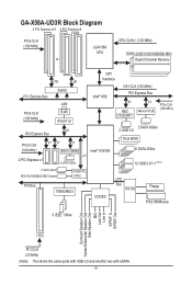
GA-X58A-UD3R Block Diagram 2 PCI Express x16 4 PCI Express x8 PCIe CLK (100 MHz) or LGA1366 CPU CPU CLK+/- (133 MHz) DDR3 2200/1333/1066/800 MHz ... x1 (100 MHz) JMicron JMB362 Intel® ICH10R 2 PCI Express x1 x1 2 eSATA 3Gb/s 2 SATA 6Gb/s 2 USB 3.0 Dual BIOS 6 SATA 3Gb/s 12 USB 2.0/1.1 (Note) 2 SATA 3Gb/s ATA-133/100/66/33 IDE Channel GIGABYTE SATA2 PCI Bus TSB43AB23 CODEC LPC Bus IT8720 Floppy PS/2 KB/Mouse 3 IEEE 1394a Surround Speaker Out Center...
GA-X58A-UD3R Block Diagram 2 PCI Express x16 4 PCI Express x8 PCIe CLK (100 MHz) or LGA1366 CPU CPU CLK+/- (133 MHz) DDR3 2200/1333/1066/800 MHz ... x1 (100 MHz) JMicron JMB362 Intel® ICH10R 2 PCI Express x1 x1 2 eSATA 3Gb/s 2 SATA 6Gb/s 2 USB 3.0 Dual BIOS 6 SATA 3Gb/s 12 USB 2.0/1.1 (Note) 2 SATA 3Gb/s ATA-133/100/66/33 IDE Channel GIGABYTE SATA2 PCI Bus TSB43AB23 CODEC LPC Bus IT8720 Floppy PS/2 KB/Mouse 3 IEEE 1394a Surround Speaker Out Center...
Manual
Page 12
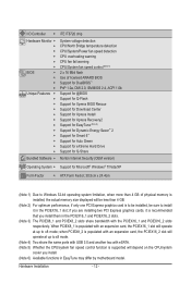
... PCIEX16_1 and PCIEX16_2 slots respectively. if you are installing two PCI Express graphics cards, it in EasyTune may differ by motherboard model. I/O Controller w Hardware Monitor w w w w w w BIOS w w w w Unique Features w w w w w w w w w w w w Bundled Software w iTE IT8720 chip System voltage detection CPU/North Bridge temperature detection CPU/System/Power fan speed detection CPU overheating warning CPU...
... PCIEX16_1 and PCIEX16_2 slots respectively. if you are installing two PCI Express graphics cards, it in EasyTune may differ by motherboard model. I/O Controller w Hardware Monitor w w w w w w BIOS w w w w Unique Features w w w w w w w w w w w w Bundled Software w iTE IT8720 chip System voltage detection CPU/North Bridge temperature detection CPU/System/Power fan speed detection CPU overheating warning CPU...
Manual
Page 16
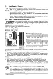
... mode with three, four or six modules, it is recommended that memory of the same capacity, brand, speed, and chips be used. (Go to GIGABYTE's website for the latest memory support list.) • Always turn off the computer and unplug the power cord from the power outlet before installing the... motherboard supports the memory. When enabling 3 Channel mode with three memory modules, be sure to install it is installed. 2. ory is installed, the BIOS will appear during the POST. A memory module can be enabled if only one DDR3 memory module is installed, be sure to install them in only...
... mode with three, four or six modules, it is recommended that memory of the same capacity, brand, speed, and chips be used. (Go to GIGABYTE's website for the latest memory support list.) • Always turn off the computer and unplug the power cord from the power outlet before installing the... motherboard supports the memory. When enabling 3 Channel mode with three memory modules, be sure to install it is installed. 2. ory is installed, the BIOS will appear during the POST. A memory module can be enabled if only one DDR3 memory module is installed, be sure to install them in only...
Manual
Page 18
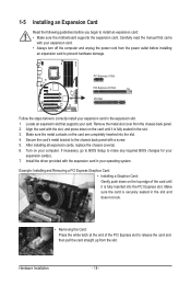
Remove the metal slot cover from the chassis back panel. 2. If necessary, go to BIOS Setup to prevent hardware damage. Carefully read the manual that supports your card. After installing all expansion cards, replace the chassis cover(s). 6. Make sure the ...; Make sure the motherboard supports the expansion card. 1-5 Installing an Expansion Card Read the following guidelines before installing an expansion card to make any required BIOS changes for your operating system.
Remove the metal slot cover from the chassis back panel. 2. If necessary, go to BIOS Setup to prevent hardware damage. Carefully read the manual that supports your card. After installing all expansion cards, replace the chassis cover(s). 6. Make sure the ...; Make sure the motherboard supports the expansion card. 1-5 Installing an Expansion Card Read the following guidelines before installing an expansion card to make any required BIOS changes for your operating system.
Manual
Page 29
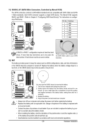
... cord and restart your computer. • Always turn off your SATA hard drive. 12) BAT The battery provides power to keep the values (such as BIOS configurations, date, and time information) in accordance with an incorrect model. • Contact the place of purchase or local dealer if you are to be...
... cord and restart your computer. • Always turn off your SATA hard drive. 12) BAT The battery provides power to keep the values (such as BIOS configurations, date, and time information) in accordance with an incorrect model. • Contact the place of purchase or local dealer if you are to be...

Manual
Page 30
... data. • RES (Reset Switch, Green): Connects to indicate the problem. The LED is on when the hard drive is detected, the BIOS may configure the way to turn off (S5). • PW (Power Switch, Red): Connects to the power switch on when the system is...chassis front panel. This function requires a chassis with a chassis intrusion switch/sensor. When connecting your system using the power switch (refer to Chapter 2, "BIOS Setup," "Power Management Setup," for information about beep codes. • HD (Hard Drive Activity LED, Blue) Connects to the chassis intrusion switch/sensor...
... data. • RES (Reset Switch, Green): Connects to indicate the problem. The LED is on when the hard drive is detected, the BIOS may configure the way to turn off (S5). • PW (Power Switch, Red): Connects to the power switch on when the system is...chassis front panel. This function requires a chassis with a chassis intrusion switch/sensor. When connecting your system using the power switch (refer to Chapter 2, "BIOS Setup," "Power Management Setup," for information about beep codes. • HD (Hard Drive Activity LED, Blue) Connects to the chassis intrusion switch/sensor...
Manual
Page 35
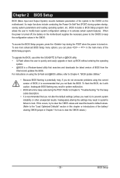
...quickly and easily upgrade or back up BIOS without entering the operating system. • @BIOS is a Windows-based utility that you not alter the default settings (unless you not flash the BIOS. To upgrade the BIOS, use either the GIGABYTE Q-Flash or @BIOS utility. • Q-Flash allows ...the user to activate certain system features. Chapter 2 BIOS Setup BIOS (Basic Input and Output System) records hardware parameters of the ...
...quickly and easily upgrade or back up BIOS without entering the operating system. • @BIOS is a Windows-based utility that you not alter the default settings (unless you not flash the BIOS. To upgrade the BIOS, use either the GIGABYTE Q-Flash or @BIOS utility. • Q-Flash allows ...the user to activate certain system features. Chapter 2 BIOS Setup BIOS (Basic Input and Output System) records hardware parameters of the ...
Manual
Page 36
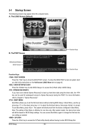
... first. Note: The setting in Boot Menu. 2-1 Startup Screen The following screens may appear when the computer boots. Motherboard Model BIOS Version X58A-UD3R F1d . . . . : BIOS Setup : XpressRecovery2 : Boot Menu : Qflash 12/23/2009-X58-ICH10-7A89QG0KC-00 Function Keys Function Keys Function Keys: : POST SCREEN Press the key to accept. ...
... first. Note: The setting in Boot Menu. 2-1 Startup Screen The following screens may appear when the computer boots. Motherboard Model BIOS Version X58A-UD3R F1d . . . . : BIOS Setup : XpressRecovery2 : Boot Menu : Qflash 12/23/2009-X58-ICH10-7A89QG0KC-00 Function Keys Function Keys Function Keys: : POST SCREEN Press the key to accept. ...
Manual
Page 37
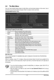
... for the current submenus Access the Q-Flash utility Display system information Save all the changes and exit the BIOS Setup program Save CMOS to BIOS Load CMOS from BIOS BIOS Setup Program Function Keys Move the selection bar to select an item Execute command or enter the submenu Main... Saving ESC: Quit F8: Q-Flash Select Item F10: Save & Exit Setup Change CPU's Clock & Voltage F11: Save CMOS to BIOS F12: Load CMOS from BIOS Main Menu Help The on-screen description of a highlighted setup option is displayed on the bottom line of the submenu. • If...
... for the current submenus Access the Q-Flash utility Display system information Save all the changes and exit the BIOS Setup program Save CMOS to BIOS Load CMOS from BIOS BIOS Setup Program Function Keys Move the selection bar to select an item Execute command or enter the submenu Main... Saving ESC: Quit F8: Q-Flash Select Item F10: Save & Exit Setup Change CPU's Clock & Voltage F11: Save CMOS to BIOS F12: Load CMOS from BIOS Main Menu Help The on-screen description of a highlighted setup option is displayed on the bottom line of the submenu. • If...
Manual
Page 38
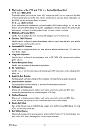
... Without Saving Abandon all the power-saving functions. PC Health Status Use this menu to configure all changes and the previous settings remain in BIOS Setup. Set User Password Change, set , or disable password. First enter the profile name (to erase the default profile name, use... this function to load the BIOS settings from BIOS If your CPU, memory, etc. Standard CMOS Features Use this menu to configure the system time and date, hard drive types, ...
... Without Saving Abandon all the power-saving functions. PC Health Status Use this menu to configure all changes and the previous settings remain in BIOS Setup. Set User Password Change, set , or disable password. First enter the profile name (to erase the default profile name, use... this function to load the BIOS settings from BIOS If your CPU, memory, etc. Standard CMOS Features Use this menu to configure the system time and date, hard drive types, ...

Manual
Page 39
... other unexpected results. (Inadequately altering the settings may result in system's failure to CPU, chipset, or memory and reduce the useful life of these components. BIOS Setup
... other unexpected results. (Inadequately altering the settings may result in system's failure to CPU, chipset, or memory and reduce the useful life of these components. BIOS Setup
Manual
Page 40
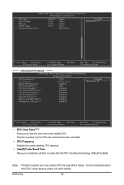
... CPU. For more information about Intel CPUs' unique features, please visit Intel's website. CPU Frequency Displays the current operating CPU frequency. Intel(R) Turbo Boost Tech. BIOS Setup - 40 - Allows you to determine whether to enable the Intel CPU Turbo Boost technology. (Default: Enabled) (Note) This item is installed. CMOS Setup Utility...
... CPU. For more information about Intel CPUs' unique features, please visit Intel's website. CPU Frequency Displays the current operating CPU frequency. Intel(R) Turbo Boost Tech. BIOS Setup - 40 - Allows you to determine whether to enable the Intel CPU Turbo Boost technology. (Default: Enabled) (Note) This item is installed. CMOS Setup Utility...

Manual
Page 41
... technology can function as multiple virtual systems. (Default: Enabled) (Note) This item is a more information about Intel CPUs' unique features, please visit Intel's website. - 41 - BIOS Setup The C3/C6/C7 state is present only if you install a CPU that supports this feature. This feature only works for operating systems that...
... technology can function as multiple virtual systems. (Default: Enabled) (Note) This item is a more information about Intel CPUs' unique features, please visit Intel's website. - 41 - BIOS Setup The C3/C6/C7 state is present only if you install a CPU that supports this feature. This feature only works for operating systems that...
Manual
Page 42
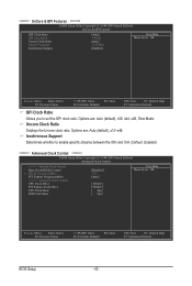
... Move Enter: Select F5: Previous Values +/-/PU/PD: Value F10: Save F6: Fail-Safe Defaults ESC: Exit F1: General Help F7: Optimized Defaults BIOS Setup - 42 - Options are : Auto (default), x12~x48. Isochronous Support Determines whether to set the QPI clock ratio. Options are : Auto (default), x36, x44, x48...
... Move Enter: Select F5: Previous Values +/-/PU/PD: Value F10: Save F6: Fail-Safe Defaults ESC: Exit F1: General Help F7: Optimized Defaults BIOS Setup - 42 - Options are : Auto (default), x12~x48. Isochronous Support Determines whether to set the QPI clock ratio. Options are : Auto (default), x36, x44, x48...
Manual
Page 43
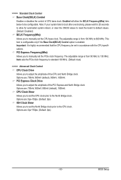
...) Control option is from 90 MHz to 600 MHz. Important: It is from 100 MHz to 150 MHz. Options are : 0ps~750ps. (Default: 0ps) - 43 - BIOS Setup The adjustable range is enabled. PCI Express Clock Drive Allows you to the North Bridge clock. Auto sets the PCIe clock frequency to standard...
...) Control option is from 90 MHz to 600 MHz. Important: It is from 100 MHz to 150 MHz. Options are : 0ps~750ps. (Default: 0ps) - 43 - BIOS Setup The adjustable range is enabled. PCI Express Clock Drive Allows you to the North Bridge clock. Auto sets the PCIe clock frequency to standard...

Manual
Page 44
Extreme Memory Profile (X.M.P.) (Note) Allows the BIOS to read the SPD data on XMP memory module(s) to the BCLK Frequency(Mhz) and System Memory Multiplier settings. Disabled Disables this item will ...Expert allows all DRAM timing control items below to set to Disabled, this function. (Default) Profile1 Uses Profile 1 settings. Options are: Auto (default), Quick, Expert. BIOS Setup - 44 - System Memory Multiplier (SPD) Allows you install a memory module that is automatically adjusted according to enhance memory performance when enabled. Profile2 (Note) Uses...
Extreme Memory Profile (X.M.P.) (Note) Allows the BIOS to read the SPD data on XMP memory module(s) to the BCLK Frequency(Mhz) and System Memory Multiplier settings. Disabled Disables this item will ...Expert allows all DRAM timing control items below to set to Disabled, this function. (Default) Profile1 Uses Profile 1 settings. Options are: Auto (default), Quick, Expert. BIOS Setup - 44 - System Memory Multiplier (SPD) Allows you install a memory module that is automatically adjusted according to enhance memory performance when enabled. Profile2 (Note) Uses...


