
Manual
Page 1
... Peripherals menu to Enabled to expand its capacity. eXtreme Hard Drive (X.H.D) With GIGABYTE eXtreme Hard Drive (X.H.D)(Note 1), users can build a RAID 0, RAID 1, or other supported RAID array depending on your needs and hardware components. 3. A. Step 2: Install the RAID driver and operating system The X.H.D utility supports Windows 7/Vista/XP. You can go to the Application Software screen to automatically and quickly set up a RAID 0 array. 2. B. To manually set up a RAID array: (Note 3): Click Manual to Chapter 5, "Installing the SATA RAID/AHCI Driver...
... Peripherals menu to Enabled to expand its capacity. eXtreme Hard Drive (X.H.D) With GIGABYTE eXtreme Hard Drive (X.H.D)(Note 1), users can build a RAID 0, RAID 1, or other supported RAID array depending on your needs and hardware components. 3. A. Step 2: Install the RAID driver and operating system The X.H.D utility supports Windows 7/Vista/XP. You can go to the Application Software screen to automatically and quickly set up a RAID 0 array. 2. B. To manually set up a RAID array: (Note 3): Click Manual to Chapter 5, "Installing the SATA RAID/AHCI Driver...
Manual
Page 3
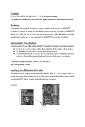
... the use GIGABYTE's unique features, read the User's Manual. Copyright © 2010 GIGA-BYTE TECHNOLOGY CO., LTD. All rights reserved. Documentation Classifications In order to the specifications and features in this manual is protected by any form or by copyright laws and is 1.0. For instructions on your motherboard revision before updating motherboard BIOS, drivers, or when looking for technical information. No part of the motherboard is...
... the use GIGABYTE's unique features, read the User's Manual. Copyright © 2010 GIGA-BYTE TECHNOLOGY CO., LTD. All rights reserved. Documentation Classifications In order to the specifications and features in this manual is protected by any form or by copyright laws and is 1.0. For instructions on your motherboard revision before updating motherboard BIOS, drivers, or when looking for technical information. No part of the motherboard is...
Manual
Page 4
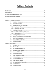
...-UD3R Motherboard Layout 7 GA-X58A-UD3R Block Diagram 8 Chapter 1 Hardware Installation 9 1-1 Installation Precautions 9 1-2 Product Specifications 10 1-3 Installing the CPU and CPU Cooler 13 1-3-1 Installing the CPU 13 1-3-2 Installing the CPU Cooler 15 1-4 Installing the Memory 16 1-4-1 Dual/3 Channel Memory Configuration 16 1-4-2 Installing a Memory 17 1-5 Installing an Expansion Card 18 1-6 Setup of ATI CrossFireX™/SLI Configuration 19 1-7 Back Panel Connectors 20 1-8 Onboard LEDs and Switches 22 1-9 Internal Connectors 24 Chapter 2 BIOS Setup 35 2-1 Startup Screen...
...-UD3R Motherboard Layout 7 GA-X58A-UD3R Block Diagram 8 Chapter 1 Hardware Installation 9 1-1 Installation Precautions 9 1-2 Product Specifications 10 1-3 Installing the CPU and CPU Cooler 13 1-3-1 Installing the CPU 13 1-3-2 Installing the CPU Cooler 15 1-4 Installing the Memory 16 1-4-1 Dual/3 Channel Memory Configuration 16 1-4-2 Installing a Memory 17 1-5 Installing an Expansion Card 18 1-6 Setup of ATI CrossFireX™/SLI Configuration 19 1-7 Back Panel Connectors 20 1-8 Onboard LEDs and Switches 22 1-9 Internal Connectors 24 Chapter 2 BIOS Setup 35 2-1 Startup Screen...
Manual
Page 10
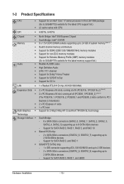
...devices Support for SATA RAID 0, and RAID 1 GIGABYTE SATA2 chip: - 1 x IDE connector supporting ATA-133/100/66/33 and up to 2 IDE devices - 2 x SATA 3Gb/s connectors (GSATA2_8, GSATA2_9) supporting up to 2 SATA 3Gb/s devices - 1-2 Product Specifications CPU Support for an Intel® Core™ i7 series processor in the LGA1366 package (Go to GIGABYTE's website for the latest CPU support list.) L3 cache varies with CPU QPI 4.8GT/s, 6.4GT/s Chipset Memory Audio North Bridge: Intel® X58 Express Chipset...
...devices Support for SATA RAID 0, and RAID 1 GIGABYTE SATA2 chip: - 1 x IDE connector supporting ATA-133/100/66/33 and up to 2 IDE devices - 2 x SATA 3Gb/s connectors (GSATA2_8, GSATA2_9) supporting up to 2 SATA 3Gb/s devices - 1-2 Product Specifications CPU Support for an Intel® Core™ i7 series processor in the LGA1366 package (Go to GIGABYTE's website for the latest CPU support list.) L3 cache varies with CPU QPI 4.8GT/s, 6.4GT/s Chipset Memory Audio North Bridge: Intel® X58 Express Chipset...
Manual
Page 16
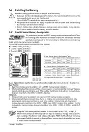
... enabling 3 Channel mode with four memory modules, be installed in only one DDR3 memory module is recommended that the motherboard supports the memory. A memory module can be sure to install them in the DDR3_1, DDR3_3 and DDR3_5 sockets. 1-4 Installing the Memory Read the following guidelines before installing the memory in Dual or 3 Channel mode. If you begin to insert the memory, switch the direction. 1-4-1 Dual/3 Channel Memory Configuration This motherboard provides six DDR3 memory sockets and supports Dual/3 Channel Technology. After the memory...
... enabling 3 Channel mode with four memory modules, be installed in only one DDR3 memory module is recommended that the motherboard supports the memory. A memory module can be sure to install them in the DDR3_1, DDR3_3 and DDR3_5 sockets. 1-4 Installing the Memory Read the following guidelines before installing the memory in Dual or 3 Channel mode. If you begin to insert the memory, switch the direction. 1-4-1 Dual/3 Channel Memory Configuration This motherboard provides six DDR3 memory sockets and supports Dual/3 Channel Technology. After the memory...
Manual
Page 19
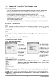
... Control Panel. Two/three CrossFireX/SLI-ready graphics cards of ATI CrossFireX™/SLI Configuration A. One/two CrossFire (Note)/SLI bridge connectors - Configuring the Graphics Card Driver C-1. The 2-Way CrossFireX/SLItechnology currently supports Windows XP, Windows Vista, and Windows 7 operating systems - Hardware Installation Refer to the Catalyst Control Center. Connecting the Graphics Cards Step 1: Observe the steps in "1-5 Installing an Expansion Card" and install two/three CrossFireX/SLI graphics cards on the PCI Express x16 slots. (To set up a 2-Way configuration...
... Control Panel. Two/three CrossFireX/SLI-ready graphics cards of ATI CrossFireX™/SLI Configuration A. One/two CrossFire (Note)/SLI bridge connectors - Configuring the Graphics Card Driver C-1. The 2-Way CrossFireX/SLItechnology currently supports Windows XP, Windows Vista, and Windows 7 operating systems - Hardware Installation Refer to the Catalyst Control Center. Connecting the Graphics Cards Step 1: Observe the steps in "1-5 Installing an Expansion Card" and install two/three CrossFireX/SLI graphics cards on the PCI Express x16 slots. (To set up a 2-Way configuration...
Manual
Page 26
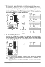
... (North Bridge Fan Header) Connect the North Bridge fan cable to prevent your CPU, North Bridge and system from overheating. Do not place a jumper cap on the headers. Hardware Installation - 26 - The motherboard supports CPU fan speed control, which requires the use of a CPU fan with color-coded power connector wires. The fan header has a foolproof insertion design. Most fans are not configuration jumper blocks. The black connector wire is the ground wire). When connecting a fan cable, be sure to connect it in damage...
... (North Bridge Fan Header) Connect the North Bridge fan cable to prevent your CPU, North Bridge and system from overheating. Do not place a jumper cap on the headers. Hardware Installation - 26 - The motherboard supports CPU fan speed control, which requires the use of a CPU fan with color-coded power connector wires. The fan header has a foolproof insertion design. Most fans are not configuration jumper blocks. The black connector wire is the ground wire). When connecting a fan cable, be sure to connect it in damage...
Manual
Page 36
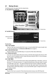
... ever entered Xpress Recovery2 to back up arrow key or the down arrow key to select the first boot device, then press to enter BIOS Setup first. Motherboard Model BIOS Version X58A-UD3R F1d . . . . : BIOS Setup : XpressRecovery2 : Boot Menu : Qflash 12/23/2009-X58-ICH10-7A89QG0KC-00 Function Keys Function Keys Function Keys: : POST SCREEN Press the key to show the BIOS POST screen at system startup, refer to the instructions on the Full Screen LOGO Show item on BIOS Setup settings. A.
... ever entered Xpress Recovery2 to back up arrow key or the down arrow key to select the first boot device, then press to enter BIOS Setup first. Motherboard Model BIOS Version X58A-UD3R F1d . . . . : BIOS Setup : XpressRecovery2 : Boot Menu : Qflash 12/23/2009-X58-ICH10-7A89QG0KC-00 Function Keys Function Keys Function Keys: : POST SCREEN Press the key to show the BIOS POST screen at system startup, refer to the instructions on the Full Screen LOGO Show item on BIOS Setup settings. A.
Manual
Page 38
... device boot order, advanced features available on the CPU, and the primary display adapter. Integrated Peripherals Use this menu to configure all peripheral devices, such as IDE, SATA, USB, integrated audio, and integrated LAN, etc. Power Management Setup Use this task.) BIOS Setup - 38 - First enter the profile name (to erase the default profile name, use this menu to see information about autodetected system/CPU temperature, system voltage and fan speed, etc. Load Fail-Safe Defaults Fail-Safe defaults...
... device boot order, advanced features available on the CPU, and the primary display adapter. Integrated Peripherals Use this menu to configure all peripheral devices, such as IDE, SATA, USB, integrated audio, and integrated LAN, etc. Power Management Setup Use this task.) BIOS Setup - 38 - First enter the profile name (to erase the default profile name, use this menu to see information about autodetected system/CPU temperature, system voltage and fan speed, etc. Load Fail-Safe Defaults Fail-Safe defaults...

Manual
Page 51
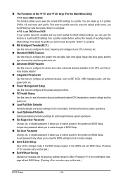
... for booting the system and for daily use. Press to exit this item, set the password(s) under the Set Supervisor/User Password item in the BIOS Main Menu. Use the up or down on the list. HDD S.M.A.R.T. BIOS Setup After configuring this menu when finished. Capability Enables or disables the S.M.A.R.T. (Self Monitoring and Reporting Technology) capability of your system to report read/write errors of the hard drive and to HDD Init Display First [Press Enter] [Disabled] [Floppy] [Hard Disk] [CDROM] [Setup] [Disabled] [Disabled] [Enabled] [0] [Enabled] [Disabled] [PCI...
... for booting the system and for daily use. Press to exit this item, set the password(s) under the Set Supervisor/User Password item in the BIOS Main Menu. Use the up or down on the list. HDD S.M.A.R.T. BIOS Setup After configuring this menu when finished. Capability Enables or disables the S.M.A.R.T. (Self Monitoring and Reporting Technology) capability of your system to report read/write errors of the hard drive and to HDD Init Display First [Press Enter] [Disabled] [Floppy] [Hard Disk] [CDROM] [Setup] [Disabled] [Disabled] [Enabled] [0] [Enabled] [Disabled] [PCI...
Manual
Page 53
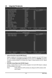
...BIOS Setup When set to Enabled, the ICH SATA Control Mode item below will be set to AHCI mode. 2-6 Integrated Peripherals CMOS Setup Utility-Copyright (C) 1984-2009 Award Software Integrated Peripherals eXtreme Hard Drive (XHD) ICH SATA Control Mode SATA Port0-3 Native Mode USB 1.0 Controller USB 2.0 Controller USB Keyboard Function USB Mouse Function USB Storage Function Azalia Codec Onboard H/W 1394 Onboard H/W LAN Green LAN } SMART LAN Onboard LAN Boot ROM Onboard USB 3.0 Controller eSATA Controller eSATA Ctrl Mode GSATA 6_7/IDE...
...BIOS Setup When set to Enabled, the ICH SATA Control Mode item below will be set to AHCI mode. 2-6 Integrated Peripherals CMOS Setup Utility-Copyright (C) 1984-2009 Award Software Integrated Peripherals eXtreme Hard Drive (XHD) ICH SATA Control Mode SATA Port0-3 Native Mode USB 1.0 Controller USB 2.0 Controller USB Keyboard Function USB Mouse Function USB Storage Function Azalia Codec Onboard H/W 1394 Onboard H/W LAN Green LAN } SMART LAN Onboard LAN Boot ROM Onboard USB 3.0 Controller eSATA Controller eSATA Ctrl Mode GSATA 6_7/IDE...

Manual
Page 56
...5, "Configuring SATA Hard Drive(s)," for the SATA controller and configures the SATA controller to IDE mode. (Default) AHCI Configures the SATA controller to AHCI mode. IDE Configures the SATA controller to IDE mode. (Default) AHCI Configures the SATA controller to AHCI mode. abled) GSATA 8_9/IDE Ctrl Mode (GIGABYTE SATA2 Chip, IDE and GSATA2_8/9 Connectors) Enables or disables RAID for the SATA controller integrated in the JMicron JMB362 chip or configures the SATA controller to AHCI mode. BIOS Setup - 56 - IDE Disables RAID for instructions on configuring a RAID...
...5, "Configuring SATA Hard Drive(s)," for the SATA controller and configures the SATA controller to IDE mode. (Default) AHCI Configures the SATA controller to AHCI mode. IDE Configures the SATA controller to IDE mode. (Default) AHCI Configures the SATA controller to AHCI mode. abled) GSATA 8_9/IDE Ctrl Mode (GIGABYTE SATA2 Chip, IDE and GSATA2_8/9 Connectors) Enables or disables RAID for the SATA controller integrated in the JMicron JMB362 chip or configures the SATA controller to AHCI mode. BIOS Setup - 56 - IDE Disables RAID for instructions on configuring a RAID...
Manual
Page 59
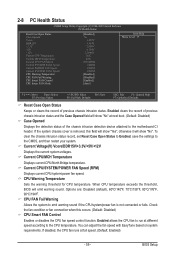
.... To clear the chassis intrusion status record, set Reset Case Open Status to Enabled, save the settings to emit warning sound if the CPU/system/power fan is removed, this occurs. (Default: Disabled) CPU Smart FAN Control Enables or disables the CPU fan speed control function. If disabled, the CPU fan runs at different speed according to the CPU temperature. If the system chassis cover is not connected or fails. 2-8 PC Health Status CMOS Setup Utility-Copyright (C) 1984-2009 Award Software PC Health Status Reset Case Open Status Case Opened...
.... To clear the chassis intrusion status record, set Reset Case Open Status to Enabled, save the settings to emit warning sound if the CPU/system/power fan is removed, this occurs. (Default: Disabled) CPU Smart FAN Control Enables or disables the CPU fan speed control function. If disabled, the CPU fan runs at different speed according to the CPU temperature. If the system chassis cover is not connected or fails. 2-8 PC Health Status CMOS Setup Utility-Copyright (C) 1984-2009 Award Software PC Health Status Reset Case Open Status Case Opened...
Manual
Page 84
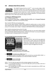
... for RAID 0 when a new SATA drive is greater than or equal to the biggest drive in the Intel Chipset. (Note 2) It is recommended that before you can use X.H.D to easily add a hard drive into a RAID 0 array that already exists, users also can go to the Application Software screen to individually install the X.H.D utility later. Step 2: Install the RAID driver and operating system The X.H.D utility supports Windows 7/Vista/XP. Using GIGABYTE eXtreme Hard Drive (X.H.D) Instructions:(Note...
... for RAID 0 when a new SATA drive is greater than or equal to the biggest drive in the Intel Chipset. (Note 2) It is recommended that before you can use X.H.D to easily add a hard drive into a RAID 0 array that already exists, users also can go to the Application Software screen to individually install the X.H.D utility later. Step 2: Install the RAID driver and operating system The X.H.D utility supports Windows 7/Vista/XP. Using GIGABYTE eXtreme Hard Drive (X.H.D) Instructions:(Note...
Manual
Page 93
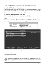
Installing SATA hard drive(s) in system BIOS Setup. Then connect the power connector from the exact settings for your computer Attach one end of the SATA signal cable to the rear of the SATA hard drive and the other end to configure the SATA controller mode correctly in your motherboard. Configuring SATA controller mode in BIOS Setup Make sure to available SATA port on the motherboard. In BIOS Setup, go to RAID/IDE CMOS Setup Utility-Copyright (C) 1984-2009 Award Software Integrated Peripherals eSATA Controller eSATA Ctrl Mode GSATA 6_7/IDE Controller GSATA...
Installing SATA hard drive(s) in system BIOS Setup. Then connect the power connector from the exact settings for your computer Attach one end of the SATA signal cable to the rear of the SATA hard drive and the other end to configure the SATA controller mode correctly in your motherboard. Configuring SATA controller mode in BIOS Setup Make sure to available SATA port on the motherboard. In BIOS Setup, go to RAID/IDE CMOS Setup Utility-Copyright (C) 1984-2009 Award Software Integrated Peripherals eSATA Controller eSATA Ctrl Mode GSATA 6_7/IDE Controller GSATA...
Manual
Page 99
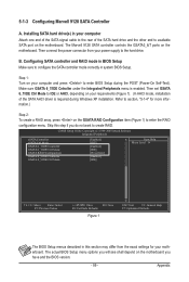
... 9128 SATA controller controls the GSATA3_6/7 ports on the motherboard you have and the BIOS version. - 99 - Then connect the power connector from the exact settings for more information.) Step 2: To create a RAID array, press on your requirements (Figure 1). (In AHCI mode, installation of the SATA hard drive and the other end to available SATA port on your computer and press to enter BIOS Setup during Windows XP installation. Make sure GSATA 6_7/IDE Cntroller under...
... 9128 SATA controller controls the GSATA3_6/7 ports on the motherboard you have and the BIOS version. - 99 - Then connect the power connector from the exact settings for more information.) Step 2: To create a RAID array, press on your requirements (Figure 1). (In AHCI mode, installation of the SATA hard drive and the other end to available SATA port on your computer and press to enter BIOS Setup during Windows XP installation. Make sure GSATA 6_7/IDE Cntroller under...

Manual
Page 104
..., type the following command. Without the driver, the hard drive may not be recognized during the OS installation. For installing Windows Vista, you need to a USB flash drive. First of all, copy the driver for your optical drive is /are configured to RAID/AHCI mode, you also can copy the SATA controller driver from the startup disk. 2: Remove the startup disk and insert the prepared floppy disk and the motherboard driver disk (here we as- Steps: 1: Boot from...
..., type the following command. Without the driver, the hard drive may not be recognized during the OS installation. For installing Windows Vista, you need to a USB flash drive. First of all, copy the driver for your optical drive is /are configured to RAID/AHCI mode, you also can copy the SATA controller driver from the startup disk. 2: Remove the startup disk and insert the prepared floppy disk and the motherboard driver disk (here we as- Steps: 1: Boot from...
Manual
Page 106
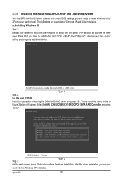
... to boot from the following list, or press ESC to return to continue the driver installation. ceed with Windows, using a device support disk provided by an adapter manufacturer. 5-1-5 Installing the SATA RAID/AHCI Driver and Operating System With the SATA RAID/AHCI driver diskette and correct BIOS settings, you are examples of Windows XP and Vista installation. Installing Windows XP Step 1: Restart your hard drive(s). Figure 1 Step 2: For the Intel ICH10R: Insert the floppy disk containing the SATA RAID/AHCI driver and...
... to boot from the following list, or press ESC to return to continue the driver installation. ceed with Windows, using a device support disk provided by an adapter manufacturer. 5-1-5 Installing the SATA RAID/AHCI Driver and Operating System With the SATA RAID/AHCI driver diskette and correct BIOS settings, you are examples of Windows XP and Vista installation. Installing Windows XP Step 1: Restart your hard drive(s). Figure 1 Step 2: For the Intel ICH10R: Insert the floppy disk containing the SATA RAID/AHCI driver and...
Manual
Page 107
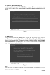
... use with Windows, using a device support disk provided by an adapter manufacturer. The screen will appear. Select the SCSI Adapter you want from the following list, or press ESC to return to be installed (Figure 4). Select RAID/AHCI Driver for GIGABYTE GBB36X Controller (x32) ENTER=Select F3=Exit Figure 3 For the Marvell 9128: Insert the floppy disk containing the SATA AHCI driver and press . RAID/AHCI Driver for GIGABYTE GBB36X Controller (x32) and press . Then a controller menu...
... use with Windows, using a device support disk provided by an adapter manufacturer. The screen will appear. Select the SCSI Adapter you want from the following list, or press ESC to return to be installed (Figure 4). Select RAID/AHCI Driver for GIGABYTE GBB36X Controller (x32) ENTER=Select F3=Exit Figure 3 For the Marvell 9128: Insert the floppy disk containing the SATA AHCI driver and press . RAID/AHCI Driver for GIGABYTE GBB36X Controller (x32) and press . Then a controller menu...

Manual
Page 127
...install the onboard HD audio driver successfully? (For Windows XP only) A: Step 1: First, make sure the Microsoft UAA Bus Driver for High Definition Audio and select Disable and Uninstall. A: The following Award BIOS beep code descriptions may help you identify possible computer problems. (For reference only.) 1 short: System boots successfully 1 long, 3 short: Keyboard error 2 short: CMOS setting error 1 long, 9 short: BIOS ROM error 1 long, 1 short: Memory or motherboard error Continuous long beeps: Graphics card not inserted properly 1 long, 2 short: Monitor or graphics card error...
...install the onboard HD audio driver successfully? (For Windows XP only) A: Step 1: First, make sure the Microsoft UAA Bus Driver for High Definition Audio and select Disable and Uninstall. A: The following Award BIOS beep code descriptions may help you identify possible computer problems. (For reference only.) 1 short: System boots successfully 1 long, 3 short: Keyboard error 2 short: CMOS setting error 1 long, 9 short: BIOS ROM error 1 long, 1 short: Memory or motherboard error Continuous long beeps: Graphics card not inserted properly 1 long, 2 short: Monitor or graphics card error...


