Manual
Page 4
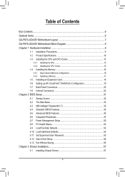
...Memory 16 1-4-1 Dual Channel Memory Configuration 16 1-4-2 Installing a Memory 17 1-5 Installing an Expansion Card 18 1-6 Setting up ATI CrossFireX™/NVIDIA SLI Configuration 19 1-7 Back Panel Connectors 20 1-8 Internal Connectors 22 Chapter 2 BIOS Setup 31 2-1 Startup Screen 32 2-2 The Main Menu 33 2-3 MB Intelligent Tweaker(M.I.T 35 2-4 Standard CMOS Features 43 2-5 Advanced BIOS Features 45 2-6 Integrated Peripherals 47 2-7 Power Management Setup 50 2-8 PC Health Status 52 2-9 Load Fail-Safe Defaults 54 2-10 Load Optimized Defaults 54 2-11 Set Supervisor/User Password...
...Memory 16 1-4-1 Dual Channel Memory Configuration 16 1-4-2 Installing a Memory 17 1-5 Installing an Expansion Card 18 1-6 Setting up ATI CrossFireX™/NVIDIA SLI Configuration 19 1-7 Back Panel Connectors 20 1-8 Internal Connectors 22 Chapter 2 BIOS Setup 31 2-1 Startup Screen 32 2-2 The Main Menu 33 2-3 MB Intelligent Tweaker(M.I.T 35 2-4 Standard CMOS Features 43 2-5 Advanced BIOS Features 45 2-6 Integrated Peripherals 47 2-7 Power Management Setup 50 2-8 PC Health Status 52 2-9 Load Fail-Safe Defaults 54 2-10 Load Optimized Defaults 54 2-11 Set Supervisor/User Password...
Manual
Page 8
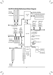
GA-P67A-UD4-B3 Motherboard Block Diagram PCIe CLK (100 MHz) 1 PCI Express x16 or 2 PCI Express x8 LGA1155 CPU CPU CLK+/- (100 MHz) DDR3 2133/1866/1600/1333/1066 MHz Dual Channel Memory x16 x8 Switch DMI Interface PCI Express Bus 2 SATA 6Gb/s LAN RJ45 Marvell Realtek 88SE9128 RTL8111E PCI Express Bus x1 x1 Intel® P67 PCIe CLK (100 MHz) x1 x1 x1 x1 3 PCI Express x1 iTE IT8892 Bridge PCI Bus CODEC 2 USB 3.0/2.0 2 USB 3.0/2.0 Renesas D720200 Renesas D720200 x1 x1...
GA-P67A-UD4-B3 Motherboard Block Diagram PCIe CLK (100 MHz) 1 PCI Express x16 or 2 PCI Express x8 LGA1155 CPU CPU CLK+/- (100 MHz) DDR3 2133/1866/1600/1333/1066 MHz Dual Channel Memory x16 x8 Switch DMI Interface PCI Express Bus 2 SATA 6Gb/s LAN RJ45 Marvell Realtek 88SE9128 RTL8111E PCI Express Bus x1 x1 Intel® P67 PCIe CLK (100 MHz) x1 x1 x1 x1 3 PCI Express x1 iTE IT8892 Bridge PCI Bus CODEC 2 USB 3.0/2.0 2 USB 3.0/2.0 Renesas D720200 Renesas D720200 x1 x1...
Manual
Page 19
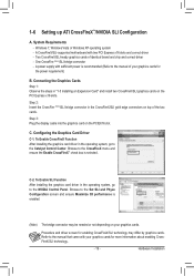
... install two CrossFireX/SLI graphics cards on the PCIEX16 slot. Procedure and driver screen for the power requirement) B. Connecting the Graphics Cards Step 1: Observe the steps in the operating system, go to the Catalyst Control Center. 1-6 Setting up ATI CrossFireX™/NVIDIA SLI Configuration A. Step 3: Plug the display cable into the graphics card on the PCI Express x16 slots. To Enable SLI Function After installing the graphics card driver in the CrossFireX/SLI gold edge connectors on your graphics cards. Browse to the manual...
... install two CrossFireX/SLI graphics cards on the PCIEX16 slot. Procedure and driver screen for the power requirement) B. Connecting the Graphics Cards Step 1: Observe the steps in the operating system, go to the Catalyst Control Center. 1-6 Setting up ATI CrossFireX™/NVIDIA SLI Configuration A. Step 3: Plug the display cable into the graphics card on the PCI Express x16 slots. To Enable SLI Function After installing the graphics card driver in the CrossFireX/SLI gold edge connectors on your graphics cards. Browse to the manual...
Manual
Page 29
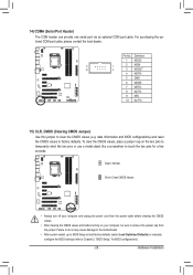
... Installation 14) COMA (Serial Port Header) The COM header can provide one serial port via an optional COM port cable. Failure to do so may cause damage to the motherboard. • After system restart, go to BIOS Setup to load factory defaults (select Load Optimized Defaults) or manually configure the BIOS settings (refer to factory defaults. Definition 1 NDCD- 9 1 2 NSIN 10 2 3 NSOUT 4 NDTR- 5 GND 6 NDSR- 7 NRTS- 8 NCTS- 9 NRI- 10 No Pin 15) CLR_CMOS (Clearing CMOS Jumper) Use this jumper to clear...
... Installation 14) COMA (Serial Port Header) The COM header can provide one serial port via an optional COM port cable. Failure to do so may cause damage to the motherboard. • After system restart, go to BIOS Setup to load factory defaults (select Load Optimized Defaults) or manually configure the BIOS settings (refer to factory defaults. Definition 1 NDCD- 9 1 2 NSIN 10 2 3 NSOUT 4 NDTR- 5 GND 6 NDSR- 7 NRTS- 8 NCTS- 9 NRI- 10 No Pin 15) CLR_CMOS (Clearing CMOS Jumper) Use this jumper to clear...
Manual
Page 32
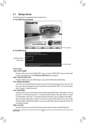
... Q-Flash utility in Boot Menu. You can be used for one time only. The system will still be based on page 46. : BIOS SETUP\Q-FLASH Press the key to enter BIOS Setup or to Xpress Recovery2 during the POST. After system restart, the device boot order will directly boot from the device configured in BIOS Setup. : XPRESS RECOVERY2 If you to the instructions on the Full Screen LOGO Show item on BIOS Setup settings. Motherboard Model BIOS Version P67A-UD4-B3 F4f . . . . : BIOS Setup...
... Q-Flash utility in Boot Menu. You can be used for one time only. The system will still be based on page 46. : BIOS SETUP\Q-FLASH Press the key to enter BIOS Setup or to Xpress Recovery2 during the POST. After system restart, the device boot order will directly boot from the device configured in BIOS Setup. : XPRESS RECOVERY2 If you to the instructions on the Full Screen LOGO Show item on BIOS Setup settings. Motherboard Model BIOS Version P67A-UD4-B3 F4f . . . . : BIOS Setup...
Manual
Page 34
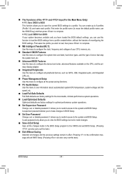
... CPU, memory, etc. Standard CMOS Features Use this menu to configure the system time and date, hard drive types, and the type of errors that stop the system boot, etc. Advanced BIOS Features Use this menu to configure the device boot order, advanced features available on the CPU, and the primary display adapter. Integrated Peripherals Use this menu to configure all peripheral devices, such as SATA, USB, integrated audio, and integrated LAN, etc. Power Management Setup Use...
... CPU, memory, etc. Standard CMOS Features Use this menu to configure the system time and date, hard drive types, and the type of errors that stop the system boot, etc. Advanced BIOS Features Use this menu to configure the device boot order, advanced features available on the CPU, and the primary display adapter. Integrated Peripherals Use this menu to configure all peripheral devices, such as SATA, USB, integrated audio, and integrated LAN, etc. Power Management Setup Use...
Manual
Page 37
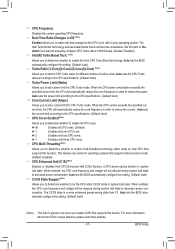
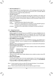
... only works for CPU Turbo mode. Set this function. Auto sets the power limit according to the CPU specifications. (Default: Auto) Core Current Limit (Amps) Allows you to determine whether to set the CPU Turbo ratios for CPU Turbo mode. CPU Multi-Threading (Note) Allows you install a CPU that support multi-processor mode. (Default: Enabled) CPU Enhanced Halt (C1E) (Note) Enables or disables Intel CPU Enhanced Halt (C1E) function, a CPU power-saving function in your operating system. When enabled, the CPU core frequency and voltage...
... only works for CPU Turbo mode. Set this function. Auto sets the power limit according to the CPU specifications. (Default: Auto) Core Current Limit (Amps) Allows you to determine whether to set the CPU Turbo ratios for CPU Turbo mode. CPU Multi-Threading (Note) Allows you install a CPU that support multi-processor mode. (Default: Enabled) CPU Enhanced Halt (C1E) (Note) Enables or disables Intel CPU Enhanced Halt (C1E) function, a CPU power-saving function in your operating system. When enabled, the CPU core frequency and voltage...
Manual
Page 38
... you install a CPU that the CPU frequency be configurable. Auto sets memory multiplier according to 2000 MHz. Disabled Disables this set the CPU base clock and DMI/PCIe bus frequency. The adjustable range is from 800 MHz to memory SPD data. (Default: Auto) Memory Frequency(Mhz) The first memory frequency value is highly recommended that supports this setting. (Default: Auto) CPU EIST Function (Note 1) Enables or disables Enhanced Intel SpeedStep Technology (EIST). Enabled will be reduced when the CPU is occurring to manually set - CPU Thermal Monitor (Note 1) Enables...
... you install a CPU that the CPU frequency be configurable. Auto sets memory multiplier according to 2000 MHz. Disabled Disables this set the CPU base clock and DMI/PCIe bus frequency. The adjustable range is from 800 MHz to memory SPD data. (Default: Auto) Memory Frequency(Mhz) The first memory frequency value is highly recommended that supports this setting. (Default: Auto) CPU EIST Function (Note 1) Enables or disables Enhanced Intel SpeedStep Technology (EIST). Enabled will be reduced when the CPU is occurring to manually set - CPU Thermal Monitor (Note 1) Enables...

Manual
Page 41
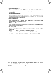
... : Auto (default), 1~255. Advanced Voltage Settings CMOS Setup Utility-Copyright (C) 1984-2010 Award Software Advanced Voltage Settings ****** Mother Board Voltage Control ****** Voltage Types Normal Current >>> CPU Load-Line Calibration [Auto] CPU Vcore 1.250V [Auto] x Dynamic Vcore(DVID) +0.000V Auto QPI/Vtt Voltage 1.050V [Auto] System Agent Voltage 0.920V [Auto] >>> MCH/ICH PCH Core 1.050V [Auto] CPU PLL 1.800V [Auto] >>> DRAM DRAM Voltage 1.500V [Auto] DRAM VRef. 0.750V [Auto] DRAM Termination 0.750V [Auto...
... : Auto (default), 1~255. Advanced Voltage Settings CMOS Setup Utility-Copyright (C) 1984-2010 Award Software Advanced Voltage Settings ****** Mother Board Voltage Control ****** Voltage Types Normal Current >>> CPU Load-Line Calibration [Auto] CPU Vcore 1.250V [Auto] x Dynamic Vcore(DVID) +0.000V Auto QPI/Vtt Voltage 1.050V [Auto] System Agent Voltage 0.920V [Auto] >>> MCH/ICH PCH Core 1.050V [Auto] CPU PLL 1.800V [Auto] >>> DRAM DRAM Voltage 1.500V [Auto] DRAM VRef. 0.750V [Auto] DRAM Termination 0.750V [Auto...

Manual
Page 42
...as multiple virtual systems. (Default: Enabled) (Note) This item is Auto. >>> DRAM DRAM Voltage The default is present only when you install a CPU that supports this feature. The default is Auto. The default is Auto. BIOS Setup - 42 - For more information about Intel CPUs' unique features, please visit Intel's website. Ch-A Address VRef. The default is Auto. Miscellaneous Settings CMOS Setup Utility-Copyright (C) 1984-2010 Award Software Miscellaneous Settings Isochronous Support Virtualization Technology (Note) [Enabled] [Enabled] Item Help Menu Level ...
...as multiple virtual systems. (Default: Enabled) (Note) This item is Auto. >>> DRAM DRAM Voltage The default is present only when you install a CPU that supports this feature. The default is Auto. The default is Auto. BIOS Setup - 42 - For more information about Intel CPUs' unique features, please visit Intel's website. Ch-A Address VRef. The default is Auto. Miscellaneous Settings CMOS Setup Utility-Copyright (C) 1984-2010 Award Software Miscellaneous Settings Isochronous Support Virtualization Technology (Note) [Enabled] [Enabled] Item Help Menu Level ...
Manual
Page 46
... display. to 3 (Note) Allows you install a CPU that supports this item to display the GIGABYTE Logo at system startup. Disabled displays normal POST message. (Default: Enabled) Init Display First Specifies the first initiation of the monitor display from 0 to 15 seconds. (Default: 0) Full Screen LOGO Show Allows you to set this feature. PCIE x8 Sets the PCI Express graphics card on the PCIEX16 slot as Windows NT4.0. (Default: Disabled) No-Execute Memory Protect (Note) Enables or disables Intel Execute Disable Bit function. BIOS Setup...
... display. to 3 (Note) Allows you install a CPU that supports this item to display the GIGABYTE Logo at system startup. Disabled displays normal POST message. (Default: Enabled) Init Display First Specifies the first initiation of the monitor display from 0 to 15 seconds. (Default: 0) Full Screen LOGO Show Allows you to set this feature. PCIE x8 Sets the PCI Express graphics card on the PCIEX16 slot as Windows NT4.0. (Default: Disabled) No-Execute Memory Protect (Note) Enables or disables Intel Execute Disable Bit function. BIOS Setup...
Manual
Page 48
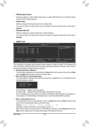
... or short. SMART LAN CMOS Setup Utility-Copyright (C) 1984-2010 Award Software SMART LAN Start detecting at Port..... Example: Part1-2 Status = Short / Length = 2m Explanation: A fault or short might occur at a normal speed of wires, the Status field will be the approximate distance to a Gigabit hub or a 10/100 Mbps hub, the following information for diagnosing your LAN cable: When No LAN Cable Is Attached... Note: Part 4-5 and Part 7-8 are not used in Windows mode...
... or short. SMART LAN CMOS Setup Utility-Copyright (C) 1984-2010 Award Software SMART LAN Start detecting at Port..... Example: Part1-2 Status = Short / Length = 2m Explanation: A fault or short might occur at a normal speed of wires, the Status field will be the approximate distance to a Gigabit hub or a 10/100 Mbps hub, the following information for diagnosing your LAN cable: When No LAN Cable Is Attached... Note: Part 4-5 and Part 7-8 are not used in Windows mode...

Manual
Page 49
...mode. Onboard Serial Port 1 Enables or disables the first serial port and specifies its base I/O address and corresponding interrupt. eSATA3 RAID Configuration (Marvell 88SE9128 Chip, eSATA Connectors on the Back Panel) Allows you to configure RAID for instructions on the Back Panel) Enables or disables the Turbo USB mode for the settings to take effect. BIOS Setup ing SATA Hard Drive(s)," for the Marvell 88SE9128 SATA controller. Auto Lets the BIOS automatically update the firmware to the latest version. (Default) Force Forces the BIOS to flash the firmware...
...mode. Onboard Serial Port 1 Enables or disables the first serial port and specifies its base I/O address and corresponding interrupt. eSATA3 RAID Configuration (Marvell 88SE9128 Chip, eSATA Connectors on the Back Panel) Allows you to configure RAID for instructions on the Back Panel) Enables or disables the Turbo USB mode for the settings to take effect. BIOS Setup ing SATA Hard Drive(s)," for the Marvell 88SE9128 SATA controller. Auto Lets the BIOS automatically update the firmware to the latest version. (Default) Force Forces the BIOS to flash the firmware...

Manual
Page 53
... fan control mode. (Default) Voltage Sets Voltage mode for CPU temperature. Current System/CPU Temperature Displays current System/CPU temperature. CPU Warning Temperature Sets the warning threshold for a 3-pin CPU fan. When CPU temperature exceeds the threshold, BIOS will emit warning sound. Check the fan condition or fan connection when this occurs. (Default: Disabled) CPU Smart FAN Control Allows you to run at full speeds. CPU/SYSTEM/POWER FAN Fail Warning Allows the system to enable the CPU fan speed control function and adjust the fan speed. This item is configurable...
... fan control mode. (Default) Voltage Sets Voltage mode for CPU temperature. Current System/CPU Temperature Displays current System/CPU temperature. CPU Warning Temperature Sets the warning threshold for a 3-pin CPU fan. When CPU temperature exceeds the threshold, BIOS will emit warning sound. Check the fan condition or fan connection when this occurs. (Default: Disabled) CPU Smart FAN Control Allows you to run at full speeds. CPU/SYSTEM/POWER FAN Fail Warning Allows the system to enable the CPU fan speed control function and adjust the fan speed. This item is configurable...
Manual
Page 65
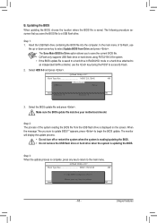
... BIOS update file is saved to a hard drive in RAID/AHCI mode or a hard drive attached to an independent SATA controller, use the up or down arrow key to select Update BIOS from Drive Save BIOS to access Q-Flash. 2. Q-Flash Utility v2.17 Flash Type/Size MXIC 25L3206E 4M Keep0 DfilMe(Is)DfaotuandEnable HDD 0-0 Loa d CMO S Default Enable Update BIOS from Drive and press . • The Save Main BIOS to Drive option allows you sure to the main menu. Make sure the BIOS update file matches your motherboard model. Unique Features B. Updating the BIOS When updating...
... BIOS update file is saved to a hard drive in RAID/AHCI mode or a hard drive attached to an independent SATA controller, use the up or down arrow key to select Update BIOS from Drive Save BIOS to access Q-Flash. 2. Q-Flash Utility v2.17 Flash Type/Size MXIC 25L3206E 4M Keep0 DfilMe(Is)DfaotuandEnable HDD 0-0 Loa d CMO S Default Enable Update BIOS from Drive and press . • The Save Main BIOS to Drive option allows you sure to the main menu. Make sure the BIOS update file matches your motherboard model. Unique Features B. Updating the BIOS When updating...
Manual
Page 77
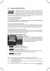
... time-consuming configurations. Step 2: Install the RAID driver and operating system The X.H.D utility supports Windows 7/Vista/XP. Without the driver, the hard drive may not be able to automatically set eXtreme Hard Drive (X.H.D) under the Integrated Peripherals menu to Enabled to enable RAID for RAID 0. To automatically set up a RAID 0 array: Click Auto to automatically and quickly set up a RAID array: (Note 3) Click Manual to access the Intel Rapid Storage Technology, with a simple click of a button, X.H.D helps to...
... time-consuming configurations. Step 2: Install the RAID driver and operating system The X.H.D utility supports Windows 7/Vista/XP. Without the driver, the hard drive may not be able to automatically set eXtreme Hard Drive (X.H.D) under the Integrated Peripherals menu to Enabled to enable RAID for RAID 0. To automatically set up a RAID 0 array: Click Auto to automatically and quickly set up a RAID array: (Note 3) Click Manual to access the Intel Rapid Storage Technology, with a simple click of a button, X.H.D helps to...

Manual
Page 87
...to the hard drive. Then set to Fw Mode. The actual BIOS Setup menu options you will see shall depend on the motherboard you do not want to available SATA port on your computer Attach one end of the SATA signal cable to the rear of the SATA AHCI driver is enabled. CMOS Setup Utility-Copyright (C) 1984-2010 Award Software Integrated Peripherals eXtreme Hard Drive (XHD) PCH SATA Control Mode SATA Port0-3 Native Mode USB Controllers USB Legacy Function USB Storage Function Azalia Codec Onboard H/W LAN } SMART LAN Onboard LAN Boot ROM R_USB30 Controller...
...to the hard drive. Then set to Fw Mode. The actual BIOS Setup menu options you will see shall depend on the motherboard you do not want to available SATA port on your computer Attach one end of the SATA signal cable to the rear of the SATA AHCI driver is enabled. CMOS Setup Utility-Copyright (C) 1984-2010 Award Software Integrated Peripherals eXtreme Hard Drive (XHD) PCH SATA Control Mode SATA Port0-3 Native Mode USB Controllers USB Legacy Function USB Storage Function Azalia Codec Onboard H/W LAN } SMART LAN Onboard LAN Boot ROM R_USB30 Controller...
Manual
Page 92
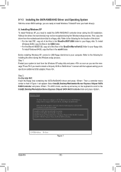
... recognized during the Windows setup process. 5-1-3 Installing the SATA RAID/AHCI Driver and Operating System With the correct BIOS settings, you to specify an additional SCSI adapter. Refer to install a 3rd party SCSI or RAID driver." Before installing Windows XP, connect a USB floppy disk drive to configure a SCSI Adapter for installing the driver during the Windows setup process. Installing Windows XP To install Windows XP, you need to install the SATA RAID/AHCI controller driver during the OS installation. To install Windows 64-Bit, copy the files in the...
... recognized during the Windows setup process. 5-1-3 Installing the SATA RAID/AHCI Driver and Operating System With the correct BIOS settings, you to specify an additional SCSI adapter. Refer to install a 3rd party SCSI or RAID driver." Before installing Windows XP, connect a USB floppy disk drive to configure a SCSI Adapter for installing the driver during the Windows setup process. Installing Windows XP To install Windows XP, you need to install the SATA RAID/AHCI controller driver during the OS installation. To install Windows 64-Bit, copy the files in the...

Manual
Page 93
... return to continue the driver installation. After the driver installation, you want from the motherboard driver disk using a device support disk provided by an adapter manufacturer. Appendix Installing Windows 7/Vista As Windows 7 and Vista already include SATA RAID/AHCI controller driver, you install all required drivers from the following list, or press ESC to return to continue the driver installation. Then select Marvell 91xx SATA Controller 32bit Driver and press . The screen will display two drivers, both of which need...
... return to continue the driver installation. After the driver installation, you want from the motherboard driver disk using a device support disk provided by an adapter manufacturer. Appendix Installing Windows 7/Vista As Windows 7 and Vista already include SATA RAID/AHCI controller driver, you install all required drivers from the following list, or press ESC to return to continue the driver installation. Then select Marvell 91xx SATA Controller 32bit Driver and press . The screen will display two drivers, both of which need...
Manual
Page 106
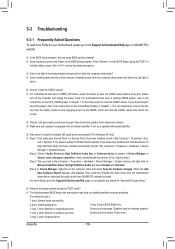
... install the onboard HD audio driver from the motherboard driver disk or download the audio driver from Microsoft's website. Q: In the BIOS Setup program, why are hidden in Device Manager or Sound, video, and game controllers. A: The following Award BIOS beep code descriptions may help you identify possible computer problems. (For reference only.) 1 short: System boots successfully 2 short: CMOS setting error 1 long, 9 short: BIOS ROM error 1 long, 1 short: Memory or motherboard error Continuous long beeps: Graphics card not inserted properly 1 long, 2 short: Monitor or graphics...
... install the onboard HD audio driver from the motherboard driver disk or download the audio driver from Microsoft's website. Q: In the BIOS Setup program, why are hidden in Device Manager or Sound, video, and game controllers. A: The following Award BIOS beep code descriptions may help you identify possible computer problems. (For reference only.) 1 short: System boots successfully 2 short: CMOS setting error 1 long, 9 short: BIOS ROM error 1 long, 1 short: Memory or motherboard error Continuous long beeps: Graphics card not inserted properly 1 long, 2 short: Monitor or graphics...


