Manual
Page 4
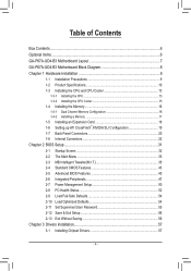
Table of Contents Box Contents...6 Optional Items...6 GA-P67A-UD4-B3 Motherboard Layout 7 GA-P67A-UD4-B3 Motherboard Block Diagram 8 Chapter 1 Hardware Installation 9 1-1 Installation Precautions 9 1-2 Product Specifications 10 1-3 Installing the CPU and CPU Cooler 13 1-3-1 Installing the CPU 13 1-3-2 Installing the CPU Cooler 15 1-4 Installing the Memory 16 1-4-1 Dual Channel Memory Configuration 16 1-4-2 Installing a Memory 17 1-5 Installing an Expansion Card 18 1-6 Setting...
Table of Contents Box Contents...6 Optional Items...6 GA-P67A-UD4-B3 Motherboard Layout 7 GA-P67A-UD4-B3 Motherboard Block Diagram 8 Chapter 1 Hardware Installation 9 1-1 Installation Precautions 9 1-2 Product Specifications 10 1-3 Installing the CPU and CPU Cooler 13 1-3-1 Installing the CPU 13 1-3-2 Installing the CPU Cooler 15 1-4 Installing the Memory 16 1-4-1 Dual Channel Memory Configuration 16 1-4-2 Installing a Memory 17 1-5 Installing an Expansion Card 18 1-6 Setting...
Manual
Page 8
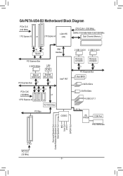
GA-P67A-UD4-B3 Motherboard Block Diagram PCIe CLK (100 MHz) 1 PCI Express x16 or 2 PCI Express x8 LGA1155 CPU CPU CLK+/- (100 MHz) DDR3 2133/1866/1600/1333/1066 MHz Dual Channel Memory x16 x8 Switch DMI Interface PCI Express Bus 2 SATA 6Gb/s LAN RJ45 Marvell Realtek 88SE9128 RTL8111E PCI Express Bus x1 x1 Intel...
GA-P67A-UD4-B3 Motherboard Block Diagram PCIe CLK (100 MHz) 1 PCI Express x16 or 2 PCI Express x8 LGA1155 CPU CPU CLK+/- (100 MHz) DDR3 2133/1866/1600/1333/1066 MHz Dual Channel Memory x16 x8 Switch DMI Interface PCI Express Bus 2 SATA 6Gb/s LAN RJ45 Marvell Realtek 88SE9128 RTL8111E PCI Express Bus x1 x1 Intel...

Manual
Page 9
... allow screws to come in a high-temperature environment. • Turning on the computer power during the installation process can become damaged as a motherboard, CPU or memory. Hardware Installation If you do not have an ESD wrist strap, keep your dealer. These stickers are no leftover screws or metal components placed on...
... allow screws to come in a high-temperature environment. • Turning on the computer power during the installation process can become damaged as a motherboard, CPU or memory. Hardware Installation If you do not have an ESD wrist strap, keep your dealer. These stickers are no leftover screws or metal components placed on...

Manual
Page 10
... Support for DDR3 2133/1866/1600/1333/1066 MHz memory modules Support for non-ECC memory modules Support for Extreme Memory Profile (XMP) memory modules (Go to GIGABYTE's website for the latest supported memory speeds and memory modules) Realtek ALC892/889 codec High Definition Audio 2/4/5.1/7.1-channel Support for Dolby®...Express graphics card is to be installed, be less than 4 GB of physical memory is installed, the actual memory size displayed will be sure to install it in the LGA1155 package (Go to GIGABYTE's website for the latest CPU support list.) L3 cache varies with the PCIEX16...
... Support for DDR3 2133/1866/1600/1333/1066 MHz memory modules Support for non-ECC memory modules Support for Extreme Memory Profile (XMP) memory modules (Go to GIGABYTE's website for the latest supported memory speeds and memory modules) Realtek ALC892/889 codec High Definition Audio 2/4/5.1/7.1-channel Support for Dolby®...Express graphics card is to be installed, be less than 4 GB of physical memory is installed, the actual memory size displayed will be sure to install it in the LGA1155 package (Go to GIGABYTE's website for the latest CPU support list.) L3 cache varies with the PCIEX16...
Manual
Page 13
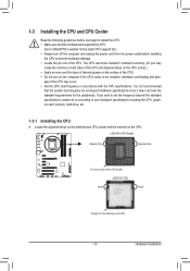
... the CPU. 1-3 Installing the CPU and CPU Cooler Read the following guidelines before installing the CPU to your hardware specifications including the CPU, graphics card, memory, hard drive, etc. 1-3-1 Installing the CPU A. The CPU cannot be set the frequency beyond hardware specifications since it does not meet the standard requirements ...bus frequency be inserted if oriented incorrectly. (Or you begin to install the CPU: • Make sure that the motherboard supports the CPU. (Go to GIGABYTE's website for the peripherals. It is not installed, otherwise overheating and dam-
... the CPU. 1-3 Installing the CPU and CPU Cooler Read the following guidelines before installing the CPU to your hardware specifications including the CPU, graphics card, memory, hard drive, etc. 1-3-1 Installing the CPU A. The CPU cannot be set the frequency beyond hardware specifications since it does not meet the standard requirements ...bus frequency be inserted if oriented incorrectly. (Or you begin to install the CPU: • Make sure that the motherboard supports the CPU. (Go to GIGABYTE's website for the peripherals. It is not installed, otherwise overheating and dam-

Manual
Page 16
...SS DDR3_2 - DS/SS DS/SS (SS=Single-Sided, DS=Double-Sided, "- -"=No Memory) DDR3_1 DDR3_2 DDR3_3 DDR3_4 Due to GIGABYTE's website for optimum performance. Enabling Dual Channel memory mode will automatically detect the specifications and capacity of the same capacity, brand, speed, and ...chips be installed in Dual Channel mode. 1. A memory module can be used . (Go to...
...SS DDR3_2 - DS/SS DS/SS (SS=Single-Sided, DS=Double-Sided, "- -"=No Memory) DDR3_1 DDR3_2 DDR3_3 DDR3_4 Due to GIGABYTE's website for optimum performance. Enabling Dual Channel memory mode will automatically detect the specifications and capacity of the same capacity, brand, speed, and ...chips be installed in Dual Channel mode. 1. A memory module can be used . (Go to...

Manual
Page 17
... steps below to correctly install your fingers on the top edge of the memory socket. Step 1: Note the orientation of the socket will snap into the memory socket. Spread the retaining clips at both ends of the memory, push down on the socket. DDR3 and DDR2 DIMMs are not compatible ...to each other or DDR DIMMs. Be sure to the memory module. 1-4-2 Installing a Memory Before installing a memory module, make sure to turn off the computer and unplug the power cord from the power outlet to prevent damage to install DDR3...
... steps below to correctly install your fingers on the top edge of the memory socket. Step 1: Note the orientation of the socket will snap into the memory socket. Spread the retaining clips at both ends of the memory, push down on the socket. DDR3 and DDR2 DIMMs are not compatible ...to each other or DDR DIMMs. Be sure to the memory module. 1-4-2 Installing a Memory Before installing a memory module, make sure to turn off the computer and unplug the power cord from the power outlet to prevent damage to install DDR3...
Manual
Page 34
... Without Saving Abandon all the power-saving functions. PC Health Status Use this function to load the BIOS settings from BIOS If your CPU, memory, etc. Standard CMOS Features Use this menu to configure the system time and date, hard drive types, and the type of reconfiguring the BIOS...
... Without Saving Abandon all the power-saving functions. PC Health Status Use this function to load the BIOS settings from BIOS If your CPU, memory, etc. Standard CMOS Features Use this menu to configure the system time and date, hard drive types, and the type of reconfiguring the BIOS...

Manual
Page 35
...Press Enter] [Press Enter] [Press Enter] [Press Enter] Item Help Menu Level BIOS Version BCLK CPU Frequency Memory Frequency Total Memory Size F4f 99.80 MHz 3094.12 MHz 1332.71 MHz 1024 MB CPU Temperature 45oC Vcore DRAM Voltage 1.280V 1.696V ...Press Enter] [Press Enter] [Press Enter] [Press Enter] Item Help Menu Level BIOS Version BCLK CPU Frequency Memory Frequency Total Memory Size F4f 99.80 MHz 3094.12 MHz 1332.71 MHz 1024 MB CPU Temperature 45oC Vcore DRAM Voltage 1.280V 1.696V...
...Press Enter] [Press Enter] [Press Enter] [Press Enter] Item Help Menu Level BIOS Version BCLK CPU Frequency Memory Frequency Total Memory Size F4f 99.80 MHz 3094.12 MHz 1332.71 MHz 1024 MB CPU Temperature 45oC Vcore DRAM Voltage 1.280V 1.696V ...Press Enter] [Press Enter] [Press Enter] [Press Enter] Item Help Menu Level BIOS Version BCLK CPU Frequency Memory Frequency Total Memory Size F4f 99.80 MHz 3094.12 MHz 1332.71 MHz 1024 MB CPU Temperature 45oC Vcore DRAM Voltage 1.280V 1.696V...

Manual
Page 36
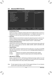
...only when you to alter the clock ratio for the installed CPU. M.I.T. The adjustable range is dependent on CPU/memory frequencies/parameters. Advanced Frequency Settings CMOS Setup Utility-Copyright (C) 1984-2010 Award Software Advanced Frequency Settings CPU Clock ...} Advanced CPU Core Features >>>>> Standard Clock Control BCLK/DMI/PEG Clock Control x BCLK/DMI/PEG Frequency (0.1MHz) Extreme Memory Profile (X.M.P.) (Note 1) System Memory Multiplier (SPD) Memory Frequency (Mhz) 1333 [31X] 3.10GHz (100x31) [Press Enter] [Disabled] 1000 100.0MHz [Disabled] [Auto] ...
...only when you to alter the clock ratio for the installed CPU. M.I.T. The adjustable range is dependent on CPU/memory frequencies/parameters. Advanced Frequency Settings CMOS Setup Utility-Copyright (C) 1984-2010 Award Software Advanced Frequency Settings CPU Clock ...} Advanced CPU Core Features >>>>> Standard Clock Control BCLK/DMI/PEG Clock Control x BCLK/DMI/PEG Frequency (0.1MHz) Extreme Memory Profile (X.M.P.) (Note 1) System Memory Multiplier (SPD) Memory Frequency (Mhz) 1333 [31X] 3.10GHz (100x31) [Press Enter] [Disabled] 1000 100.0MHz [Disabled] [Auto] ...
Manual
Page 38
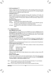
... loading, Intel EIST technology can dynamically and effectively lower the CPU voltage and core frequency to the BCLK/DMI/PEG Frequency(0.1MHz) and System Memory Multiplier settings. (Note 1) This item is present only when you to be set - Profile2 (Note 2) Uses Profile 2 settings. the...enabled, the CPU core frequency and voltage will be reduced when the CPU is present only when you to 2000 MHz. Depending on XMP memory module(s) to decrease heat production. The adjustable range is enabled. CPU Thermal Monitor (Note 1) Enables or disables Intel CPU Thermal Monitor ...
... loading, Intel EIST technology can dynamically and effectively lower the CPU voltage and core frequency to the BCLK/DMI/PEG Frequency(0.1MHz) and System Memory Multiplier settings. (Note 1) This item is present only when you to be set - Profile2 (Note 2) Uses Profile 2 settings. the...enabled, the CPU core frequency and voltage will be reduced when the CPU is present only when you to 2000 MHz. Depending on XMP memory module(s) to decrease heat production. The adjustable range is enabled. CPU Thermal Monitor (Note 1) Enables or disables Intel CPU Thermal Monitor ...

Manual
Page 39
... Value F10: Save F6: Fail-Safe Defaults ESC: Exit F1: General Help F7: Optimized Defaults Extreme Memory Profile (X.M.P.) , (Note) System Memory Multiplier (SPD), Memory Frequency(Mhz) The settings under the three items above are : Auto (default), Quick, Expert. Performance Enhance...Channel B Timing Settings items to Profile1 or Profile2, this setting. (Default: Auto) Rank Interleaving Enables or disables memory rank interleaving. When Extreme Memory Profile (X.M.P.) is dependent on the Advanced Frequency Settings menu. Turbo Lets the system operate at its good performance ...
... Value F10: Save F6: Fail-Safe Defaults ESC: Exit F1: General Help F7: Optimized Defaults Extreme Memory Profile (X.M.P.) , (Note) System Memory Multiplier (SPD), Memory Frequency(Mhz) The settings under the three items above are : Auto (default), Quick, Expert. Performance Enhance...Channel B Timing Settings items to Profile1 or Profile2, this setting. (Default: Auto) Rank Interleaving Enables or disables memory rank interleaving. When Extreme Memory Profile (X.M.P.) is dependent on the Advanced Frequency Settings menu. Turbo Lets the system operate at its good performance ...

Manual
Page 43
... } IDE Channel 4 Master } IDE Channel 4 Slave } IDE Channel 5 Master [None] [None] [None] [None] [None] [None] [None] [None] [None] Halt On [All, But Keyboard] Base Memory Extended Memory Total Memory 640K 1022M 1024M Move Enter: Select F5: Previous Values +/-/PU/PD: Value F10: Save F6: Fail-Safe Defaults ESC: Exit F1: General Help F7...
... } IDE Channel 4 Master } IDE Channel 4 Slave } IDE Channel 5 Master [None] [None] [None] [None] [None] [None] [None] [None] [None] Halt On [All, But Keyboard] Base Memory Extended Memory Total Memory 640K 1022M 1024M Move Enter: Select F5: Previous Values +/-/PU/PD: Value F10: Save F6: Fail-Safe Defaults ESC: Exit F1: General Help F7...
Manual
Page 44
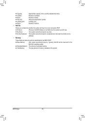
... whether the system will stop for any error. Extended Memory The amount of cylinders. Landing zone. No Errors The system boot will be reserved for a keyboard error but stop . Base Memory Also called conventional memory. Write precompensation cylinder. BIOS Setup - 44 - Typically..., 640 KB will not stop for all other errors. (Default) Memory These fields are read-only and are determined by the BIOS...
... whether the system will stop for any error. Extended Memory The amount of cylinders. Landing zone. No Errors The system boot will be reserved for a keyboard error but stop . Base Memory Also called conventional memory. Write precompensation cylinder. BIOS Setup - 44 - Typically..., 640 KB will not stop for all other errors. (Default) Memory These fields are read-only and are determined by the BIOS...
Manual
Page 45
... disables the quick boot function to speed up the system boot-up or down arrow key to select a device and press to 3 (Note) No-Execute Memory Protect (Note) Delay For HDD (Secs) Full Screen LOGO Show Init Display First [Press Enter] [Disabled] [Hard Disk] [CDROM] [USB-FDD] [Setup] [Disabled] [Disabled] [Enabled...
... disables the quick boot function to speed up the system boot-up or down arrow key to select a device and press to 3 (Note) No-Execute Memory Protect (Note) Delay For HDD (Secs) Full Screen LOGO Show Init Display First [Press Enter] [Disabled] [Hard Disk] [CDROM] [USB-FDD] [Setup] [Disabled] [Disabled] [Enabled...
Manual
Page 46
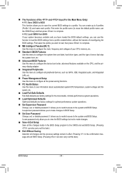
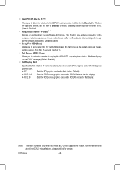
This function may enhance protection for the computer, reducing exposure to display the GIGABYTE Logo at system startup. PCIE x8 Sets the PCI Express graphics card on the PCIEX16 slot as the system boots up. For more information about ... card as the first display. (Default) PCIE x16 Sets the PCI Express graphics card on the PCIEX8 slot as Windows NT4.0. (Default: Disabled) No-Execute Memory Protect (Note) Enables or disables Intel Execute Disable Bit function. Disabled displays normal POST message. (Default: Enabled) Init Display First Specifies the first initiation of...
This function may enhance protection for the computer, reducing exposure to display the GIGABYTE Logo at system startup. PCIE x8 Sets the PCI Express graphics card on the PCIEX16 slot as the system boots up. For more information about ... card as the first display. (Default) PCIE x16 Sets the PCI Express graphics card on the PCIEX8 slot as Windows NT4.0. (Default: Disabled) No-Execute Memory Protect (Note) Enables or disables Intel Execute Disable Bit function. Disabled displays normal POST message. (Default: Enabled) Init Display First Specifies the first initiation of...

Manual
Page 51
... Windows 7/Vista; Note: To use this function, you need an ATX power supply providing at least 1A on the system, enter the password and press . Memory The system returns to its last known awake state upon the return of the AC power. (Default) Full-On The system is turned on this...
... Windows 7/Vista; Note: To use this function, you need an ATX power supply providing at least 1A on the system, enter the password and press . Memory The system returns to its last known awake state upon the return of the AC power. (Default) Full-On The system is turned on this...

Manual
Page 61
... Recovery2 will save the backup file at which the data is the first physical drive. - 61 - System Requirements: • At least 512 MB of system memory • VESA compatible graphics card • Windows XP with Xpress Recovery cannot be restored using Xpress Recovery2. • USB hard drives are not supported. •...
... Recovery2 will save the backup file at which the data is the first physical drive. - 61 - System Requirements: • At least 512 MB of system memory • VESA compatible graphics card • Windows XP with Xpress Recovery cannot be restored using Xpress Recovery2. • USB hard drives are not supported. •...

Manual
Page 68
... CPU and memory information, letting users read their system settings or do the overclock/overvoltage, make sure that the item is not configurable or the function is a simple and easy-to-use your ATI or NVIDIA graphics card. The HW Monitor tab allows you set temperature/fan speed alarm. 4-3 EasyTune 6 GIGABYTE's EasyTune...
... CPU and memory information, letting users read their system settings or do the overclock/overvoltage, make sure that the item is not configurable or the function is a simple and easy-to-use your ATI or NVIDIA graphics card. The HW Monitor tab allows you set temperature/fan speed alarm. 4-3 EasyTune 6 GIGABYTE's EasyTune...

Manual
Page 70
... power savings they have accumulated in a set to Enabled. (Note 2) 1: Smart FAN/CPU (default); 2: Smart FAN/CPU/VGA/HDD; 3: Smart FAN/CPU/VGA/HDD/Chipset/ Memory. (Note 3) The total amount of the devices currently in taskbar) 14 INFO/Help 15 Motherboard Phase LED On/Off Switch (Default: On) 16 Live Utility...
... power savings they have accumulated in a set to Enabled. (Note 2) 1: Smart FAN/CPU (default); 2: Smart FAN/CPU/VGA/HDD; 3: Smart FAN/CPU/VGA/HDD/Chipset/ Memory. (Note 3) The total amount of the devices currently in taskbar) 14 INFO/Help 15 Motherboard Phase LED On/Off Switch (Default: On) 16 Live Utility...


