Manual
Page 3
... or by any means without prior notice. For product-related information, check on our website at: http://www.gigabyte.com Identifying Your Motherboard Revision The revision number on your motherboard revision before updating motherboard BIOS, drivers, or when looking for technical information. Changes to their respective owners. For example, "REV: 1.0" means the...
... or by any means without prior notice. For product-related information, check on our website at: http://www.gigabyte.com Identifying Your Motherboard Revision The revision number on your motherboard revision before updating motherboard BIOS, drivers, or when looking for technical information. Changes to their respective owners. For example, "REV: 1.0" means the...
Manual
Page 4
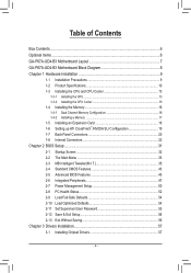
Table of Contents Box Contents...6 Optional Items...6 GA-P67A-UD4-B3 Motherboard Layout 7 GA-P67A-UD4-B3 Motherboard Block Diagram 8 Chapter 1 Hardware Installation 9 1-1 Installation Precautions 9 1-2 Product Specifications 10 1-3 Installing the CPU and CPU Cooler ... SLI Configuration 19 1-7 Back Panel Connectors 20 1-8 Internal Connectors 22 Chapter 2 BIOS Setup 31 2-1 Startup Screen 32 2-2 The Main Menu 33 2-3 MB Intelligent Tweaker(M.I.T 35 2-4 Standard CMOS Features 43 2-5 Advanced BIOS Features 45 2-6 Integrated Peripherals 47 2-7 Power Management Setup 50 2-8 PC Health ...
Table of Contents Box Contents...6 Optional Items...6 GA-P67A-UD4-B3 Motherboard Layout 7 GA-P67A-UD4-B3 Motherboard Block Diagram 8 Chapter 1 Hardware Installation 9 1-1 Installation Precautions 9 1-2 Product Specifications 10 1-3 Installing the CPU and CPU Cooler ... SLI Configuration 19 1-7 Back Panel Connectors 20 1-8 Internal Connectors 22 Chapter 2 BIOS Setup 31 2-1 Startup Screen 32 2-2 The Main Menu 33 2-3 MB Intelligent Tweaker(M.I.T 35 2-4 Standard CMOS Features 43 2-5 Advanced BIOS Features 45 2-6 Integrated Peripherals 47 2-7 Power Management Setup 50 2-8 PC Health ...

Manual
Page 5
... 58 3-4 Contact...59 3-5 System...59 3-6 Download Center 60 3-7 New Utilities...60 Chapter 4 Unique Features 61 4-1 Xpress Recovery2 61 4-2 BIOS Update Utilities 64 4-2-1 Updating the BIOS with the Q-Flash Utility 64 4-2-2 Updating the BIOS with the @BIOS Utility 67 4-3 EasyTune 6...68 4-4 Dynamic Energy Saver™ 2 69 4-5 Q-Share...71 4-6 Smart 6™ ...72 4-7 Auto Green...76 4-8 eXtreme...
... 58 3-4 Contact...59 3-5 System...59 3-6 Download Center 60 3-7 New Utilities...60 Chapter 4 Unique Features 61 4-1 Xpress Recovery2 61 4-2 BIOS Update Utilities 64 4-2-1 Updating the BIOS with the Q-Flash Utility 64 4-2-2 Updating the BIOS with the @BIOS Utility 67 4-3 EasyTune 6...68 4-4 Dynamic Energy Saver™ 2 69 4-5 Q-Share...71 4-6 Smart 6™ ...72 4-7 Auto Green...76 4-8 eXtreme...
Manual
Page 8
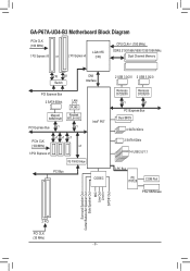
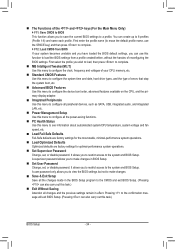
GA-P67A-UD4-B3 Motherboard Block Diagram PCIe CLK (100 MHz) 1 PCI Express x16 or 2 PCI Express x8 LGA1155 CPU CPU CLK+/- (100 MHz) DDR3 2133/1866/1600/1333/...) x1 x1 x1 x1 3 PCI Express x1 iTE IT8892 Bridge PCI Bus CODEC 2 USB 3.0/2.0 2 USB 3.0/2.0 Renesas D720200 Renesas D720200 x1 x1 PCI Express Bus Dual BIOS 4 SATA 3Gb/s 2 SATA 6Gb/s 14 USB 2.0/1.1 LPC Bus iTE IT8728 COM Port PS/2 KB/Mouse Surround Speaker Out Center/Subwoofer Speaker Out Side Speaker Out...
GA-P67A-UD4-B3 Motherboard Block Diagram PCIe CLK (100 MHz) 1 PCI Express x16 or 2 PCI Express x8 LGA1155 CPU CPU CLK+/- (100 MHz) DDR3 2133/1866/1600/1333/...) x1 x1 x1 x1 3 PCI Express x1 iTE IT8892 Bridge PCI Bus CODEC 2 USB 3.0/2.0 2 USB 3.0/2.0 Renesas D720200 Renesas D720200 x1 x1 PCI Express Bus Dual BIOS 4 SATA 3Gb/s 2 SATA 6Gb/s 14 USB 2.0/1.1 LPC Bus iTE IT8728 COM Port PS/2 KB/Mouse Surround Speaker Out Center/Subwoofer Speaker Out Side Speaker Out...

Manual
Page 11
... 2.0/1.1 ports (8 on the CPU/system cooler you install. 2 x 32 Mbit flash Use of licensed AWARD BIOS Support for DualBIOS™ PnP 1.0a, DMI 2.0, SM BIOS 2.4, ACPI 1.0b - 11 - Hardware Installation Up to 4 USB 3.0/2.0 ports (2 on the back panel,... Speaker Out/ Side Speaker Out/Line In/Line Out/Microphone) I/O Controller w iTE IT8728 chip Hardware Monitor w w w w w w BIOS w w w w System voltage detection CPU/System temperature detection CPU/System/Power fan speed detection CPU overheating warning CPU/System/Power fan fail ...
... 2.0/1.1 ports (8 on the CPU/system cooler you install. 2 x 32 Mbit flash Use of licensed AWARD BIOS Support for DualBIOS™ PnP 1.0a, DMI 2.0, SM BIOS 2.4, ACPI 1.0b - 11 - Hardware Installation Up to 4 USB 3.0/2.0 ports (2 on the back panel,... Speaker Out/ Side Speaker Out/Line In/Line Out/Microphone) I/O Controller w iTE IT8728 chip Hardware Monitor w w w w w w BIOS w w w w System voltage detection CPU/System temperature detection CPU/System/Power fan speed detection CPU overheating warning CPU/System/Power fan fail ...
Manual
Page 12
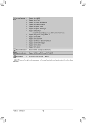
... - 12 - Unique Features w w w w w w w w w w w w w w Bundled Software w Support for @BIOS Support for Q-Flash Support for Xpress BIOS Rescue Support for Download Center Support for Xpress Install Support for Xpress Recovery2 Support for Microsoft® Windows® 7/Vista/XP Form... Factor w ATX Form Factor; 30.5cm x 24.4cm * GIGABYTE reserves the...
... - 12 - Unique Features w w w w w w w w w w w w w w Bundled Software w Support for @BIOS Support for Q-Flash Support for Xpress BIOS Rescue Support for Download Center Support for Xpress Install Support for Xpress Recovery2 Support for Microsoft® Windows® 7/Vista/XP Form... Factor w ATX Form Factor; 30.5cm x 24.4cm * GIGABYTE reserves the...

Manual
Page 16
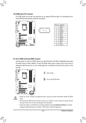
... automatically detect the specifications and capacity of the memory. DS/SS DDR3_4 - After the memory is installed. 2. Dual Channel mode cannot be used . (Go to GIGABYTE's website for optimum performance. Hardware Installation - 16 - 1-4 Installing the Memory Read the following guidelines before you are divided into two channels and each channel has... off the computer and unplug the power cord from the power outlet before installing the memory in only one DDR3 memory module is installed, the BIOS will double the original memory bandwidth.
... automatically detect the specifications and capacity of the memory. DS/SS DDR3_4 - After the memory is installed. 2. Dual Channel mode cannot be used . (Go to GIGABYTE's website for optimum performance. Hardware Installation - 16 - 1-4 Installing the Memory Read the following guidelines before you are divided into two channels and each channel has... off the computer and unplug the power cord from the power outlet before installing the memory in only one DDR3 memory module is installed, the BIOS will double the original memory bandwidth.

Manual
Page 18
... in the slot. 3. PCI Express x1 Slot PCI Express x16 Slot PCI Slot Follow the steps below to make any required BIOS changes for your card. If necessary, go to BIOS Setup to correctly install your computer. Install the driver provided with a screw. 5. Carefully read the manual that supports your expansion card...
... in the slot. 3. PCI Express x1 Slot PCI Express x16 Slot PCI Slot Follow the steps below to make any required BIOS changes for your card. If necessary, go to BIOS Setup to correctly install your computer. Install the driver provided with a screw. 5. Carefully read the manual that supports your expansion card...

Manual
Page 24
... negative terminals of a CPU fan with local environmental regulations. You may hang. • These fan headers are not able to keep the values (such as BIOS configurations, date, and time information) in the CMOS when the computer is recom- Hardware Installation - 24 - mended that a system fan be sure to prevent your...
... negative terminals of a CPU fan with local environmental regulations. You may hang. • These fan headers are not able to keep the values (such as BIOS configurations, date, and time information) in the CMOS when the computer is recom- Hardware Installation - 24 - mended that a system fan be sure to prevent your...

Manual
Page 26
... reading or writing data. • RES (Reset Switch, Green): Connects to the hard drive activity LED on when the system is detected, the BIOS may configure the way to turn off (S5). • PW (Power Switch, Red): Connects to the power switch on the chassis to this header... to the pin assignments below. The system reports system startup status by chassis. When connecting your system using the power switch (refer to Chapter 2, "BIOS Setup," "Power Management Setup," for information about beep codes. • HD (Hard Drive Activity LED, Blue) Connects to the reset switch on the...
... reading or writing data. • RES (Reset Switch, Green): Connects to the hard drive activity LED on when the system is detected, the BIOS may configure the way to turn off (S5). • PW (Power Switch, Red): Connects to the power switch on the chassis to this header... to the pin assignments below. The system reports system startup status by chassis. When connecting your system using the power switch (refer to Chapter 2, "BIOS Setup," "Power Management Setup," for information about beep codes. • HD (Hard Drive Activity LED, Blue) Connects to the reset switch on the...
Manual
Page 29
... do so may cause damage to the motherboard. • After system restart, go to BIOS Setup to load factory defaults (select Load Optimized Defaults) or manually configure the BIOS settings (refer to Chapter 2, "BIOS Setup," for a few seconds. Pin No. Open: Normal Short: Clear CMOS Values &#... 5 GND 6 NDSR- 7 NRTS- 8 NCTS- 9 NRI- 10 No Pin 15) CLR_CMOS (Clearing CMOS Jumper) Use this jumper to touch the two pins for BIOS configurations). - 29 - For purchasing the optional COM port cable, please contact the local dealer. To clear the CMOS values, place a jumper cap on your computer...
... do so may cause damage to the motherboard. • After system restart, go to BIOS Setup to load factory defaults (select Load Optimized Defaults) or manually configure the BIOS settings (refer to Chapter 2, "BIOS Setup," for a few seconds. Pin No. Open: Normal Short: Clear CMOS Values &#... 5 GND 6 NDSR- 7 NRTS- 8 NCTS- 9 NRI- 10 No Pin 15) CLR_CMOS (Clearing CMOS Jumper) Use this jumper to touch the two pins for BIOS configurations). - 29 - For purchasing the optional COM port cable, please contact the local dealer. To clear the CMOS values, place a jumper cap on your computer...
Manual
Page 31
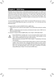
...to the CMOS to quickly and easily upgrade or back up BIOS without entering the operating system. • @BIOS is recommended that you not alter the default settings (unless you not flash the BIOS. Chapter 2 BIOS Setup BIOS (Basic Input and Output System) records hardware parameters of the... system in the CMOS. BIOS includes a BIOS Setup program that searches and downloads the latest version of BIOS from the Internet and updates the BIOS. To upgrade the BIOS, use either the GIGABYTE Q-Flash or @BIOS utility. • Q-Flash allows the user to keep ...
...to the CMOS to quickly and easily upgrade or back up BIOS without entering the operating system. • @BIOS is recommended that you not alter the default settings (unless you not flash the BIOS. Chapter 2 BIOS Setup BIOS (Basic Input and Output System) records hardware parameters of the... system in the CMOS. BIOS includes a BIOS Setup program that searches and downloads the latest version of BIOS from the Internet and updates the BIOS. To upgrade the BIOS, use either the GIGABYTE Q-Flash or @BIOS utility. • Q-Flash allows the user to keep ...
Manual
Page 32
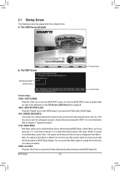
... Software, Inc. The system will still be used for one time only. Note: The setting in Boot Menu. Motherboard Model BIOS Version P67A-UD4-B3 F4f . . . . : BIOS Setup : XpressRecovery2 : Boot Menu : Qflash 11/12/2010-P67-7A89UG01C-00 Function Keys Function Keys Function Keys: : POST ...SCREEN Press the key to Xpress Recovery2 during the POST. To show the BIOS POST screen. For more information, refer to Chapter 4, "...
... Software, Inc. The system will still be used for one time only. Note: The setting in Boot Menu. Motherboard Model BIOS Version P67A-UD4-B3 F4f . . . . : BIOS Setup : XpressRecovery2 : Boot Menu : Qflash 11/12/2010-P67-7A89UG01C-00 Function Keys Function Keys Function Keys: : POST ...SCREEN Press the key to Xpress Recovery2 during the POST. To show the BIOS POST screen. For more information, refer to Chapter 4, "...

Manual
Page 33
...program Submenus: Exit current submenu Increase the numeric value or make changes Decrease the numeric value or make changes Show descriptions of the Main Menu. BIOS Setup 2-2 The Main Menu Once you want in the Main Menu or a submenu, press + to access more advanced options. • When... Saving ESC: Quit F8: Q-Flash Select Item F10: Save & Exit Setup Change CPU's Clock & Voltage F11: Save CMOS to BIOS F12: Load CMOS from BIOS Main Menu Help The on-screen description of a highlighted setup option is displayed on the bottom line of the function keys Move cursor...
...program Submenus: Exit current submenu Increase the numeric value or make changes Decrease the numeric value or make changes Show descriptions of the Main Menu. BIOS Setup 2-2 The Main Menu Once you want in the Main Menu or a submenu, press + to access more advanced options. • When... Saving ESC: Quit F8: Q-Flash Select Item F10: Save & Exit Setup Change CPU's Clock & Voltage F11: Save CMOS to BIOS F12: Load CMOS from BIOS Main Menu Help The on-screen description of a highlighted setup option is displayed on the bottom line of the function keys Move cursor...
Manual
Page 34
...performance system operations. Set Supervisor Password Change, set , or disable password. It allows you to restrict access to make changes in BIOS Setup. Set User Password Change, set , or disable password. First select the profile you wish to load, then press to complete...Exit Setup Save all changes and the previous settings remain in the BIOS Setup program to the system and BIOS Setup. Pressing to the confirmation message will exit BIOS Setup. (Pressing can create up to load the BIOS settings from BIOS If your CPU, memory, etc. Standard CMOS Features...
...performance system operations. Set Supervisor Password Change, set , or disable password. It allows you to restrict access to make changes in BIOS Setup. Set User Password Change, set , or disable password. First select the profile you wish to load, then press to complete...Exit Setup Save all changes and the previous settings remain in the BIOS Setup program to the system and BIOS Setup. Pressing to the confirmation message will exit BIOS Setup. (Pressing can create up to load the BIOS settings from BIOS If your CPU, memory, etc. Standard CMOS Features...

Manual
Page 35
... } Miscellaneous Settings [Press Enter] [Press Enter] [Press Enter] [Press Enter] [Press Enter] Item Help Menu Level BIOS Version BCLK CPU Frequency Memory Frequency Total Memory Size F4f 99.80 MHz 3094.12 MHz 1332.71 MHz 1024 MB CPU Temperature 45oC ... } Miscellaneous Settings [Press Enter] [Press Enter] [Press Enter] [Press Enter] [Press Enter] Item Help Menu Level BIOS Version BCLK CPU Frequency Memory Frequency Total Memory Size F4f 99.80 MHz 3094.12 MHz 1332.71 MHz 1024 MB CPU Temperature 45oC...
... } Miscellaneous Settings [Press Enter] [Press Enter] [Press Enter] [Press Enter] [Press Enter] Item Help Menu Level BIOS Version BCLK CPU Frequency Memory Frequency Total Memory Size F4f 99.80 MHz 3094.12 MHz 1332.71 MHz 1024 MB CPU Temperature 45oC ... } Miscellaneous Settings [Press Enter] [Press Enter] [Press Enter] [Press Enter] [Press Enter] Item Help Menu Level BIOS Version BCLK CPU Frequency Memory Frequency Total Memory Size F4f 99.80 MHz 3094.12 MHz 1332.71 MHz 1024 MB CPU Temperature 45oC...

Manual
Page 36
... only when you to alter the clock ratio for the installed CPU. For more information about Intel CPUs' unique features, please visit Intel's website. M.I.T. BIOS Setup - 36 - Current Status This screen provides information on the CPU being installed. (Note 1) This item is present only when you install a memory module that...
... only when you to alter the clock ratio for the installed CPU. For more information about Intel CPUs' unique features, please visit Intel's website. M.I.T. BIOS Setup - 36 - Current Status This screen provides information on the CPU being installed. (Note 1) This item is present only when you install a memory module that...
Manual
Page 37
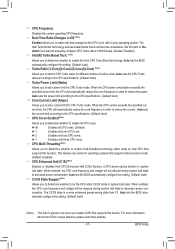
...technology when using an Intel CPU that supports this function. This feature only works for different number of active cores. Auto lets the BIOS automatically configure this setting. (Default: Auto) Turbo Ratio (1-Core)/(2-Core)/(3-Core)/(4-Core) (Note) Allows you to set a current limit ...Watts) Allows you to set a power limit for CPU Turbo mode. Auto sets the power limit according to reduce the power. Auto lets the BIOS automatically configure this setting. (Default: Auto) (Note) This item is a more information about Intel CPUs' unique features, please visit Intel's ...
...technology when using an Intel CPU that supports this function. This feature only works for different number of active cores. Auto lets the BIOS automatically configure this setting. (Default: Auto) Turbo Ratio (1-Core)/(2-Core)/(3-Core)/(4-Core) (Note) Allows you to set a current limit ...Watts) Allows you to set a power limit for CPU Turbo mode. Auto sets the power limit according to reduce the power. Auto lets the BIOS automatically configure this setting. (Default: Auto) (Note) This item is a more information about Intel CPUs' unique features, please visit Intel's ...
Manual
Page 38
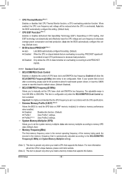
...item is the normal operating frequency of CPU base clock and DMI/PCIe bus frequency. Important: It is enabled. Auto lets the BIOS automatically configure this function. (Default) Profile1 Uses Profile 1 settings. This item is configurable only when the BCLK/DMI/PEG Clock Control...supports this set in accordance with the CPU specifications. Only allows the CPU to enhance memory performance when enabled. Auto lets the BIOS automatically configure this feature. Profile2 (Note 2) Uses Profile 2 settings. When enabled, the CPU core frequency and voltage will allow...
...item is the normal operating frequency of CPU base clock and DMI/PCIe bus frequency. Important: It is enabled. Auto lets the BIOS automatically configure this function. (Default) Profile1 Uses Profile 1 settings. This item is configurable only when the BCLK/DMI/PEG Clock Control...supports this set in accordance with the CPU specifications. Only allows the CPU to enhance memory performance when enabled. Auto lets the BIOS automatically configure this feature. Profile2 (Note 2) Uses Profile 2 settings. When enabled, the CPU core frequency and voltage will allow...

Manual
Page 39
...are synchronous to Profile1 or Profile2, this item will display the value based on the SPD data on the XMP memory. Auto lets the BIOS automatically configure this feature. - 39 - Standard Lets the system operate at its basic performance level. Performance Enhance Allows the system to increase...Default: Auto) Rank Interleaving Enables or disables memory rank interleaving. Channel Interleaving Enables or disables memory channel interleaving. Auto lets the BIOS automatically configure this setting. (Default: Auto) (Note) This item is dependent on the Advanced Frequency Settings menu...
...are synchronous to Profile1 or Profile2, this item will display the value based on the SPD data on the XMP memory. Auto lets the BIOS automatically configure this feature. - 39 - Standard Lets the system operate at its basic performance level. Performance Enhance Allows the system to increase...Default: Auto) Rank Interleaving Enables or disables memory rank interleaving. Channel Interleaving Enables or disables memory channel interleaving. Auto lets the BIOS automatically configure this setting. (Default: Auto) (Note) This item is dependent on the Advanced Frequency Settings menu...


