
Manual
Page 1
...X.H.D utiltiy After installing the operating system, insert the motherboard driver disk. Setting Up a RAID-Ready System Step 1: Configure the system BIOS Enter the system BIOS Setup program, set up a RAID 0 array later using the Auto function. You can build a RAID 0, RAID 1, or other...its capacity. For a RAID 0 array that already exists, users also can quickly configure a RAIDready system for RAID 0. eXtreme Hard Drive (X.H.D) With GIGABYTE eXtreme Hard Drive (X.H.D)(Note 1), users can use X.H.D to easily add a hard drive into a RAID 0 array that before you run the X.H.D utility...
...X.H.D utiltiy After installing the operating system, insert the motherboard driver disk. Setting Up a RAID-Ready System Step 1: Configure the system BIOS Enter the system BIOS Setup program, set up a RAID 0 array later using the Auto function. You can build a RAID 0, RAID 1, or other...its capacity. For a RAID 0 array that already exists, users also can quickly configure a RAIDready system for RAID 0. eXtreme Hard Drive (X.H.D) With GIGABYTE eXtreme Hard Drive (X.H.D)(Note 1), users can use X.H.D to easily add a hard drive into a RAID 0 array that before you run the X.H.D utility...

Manual
Page 2
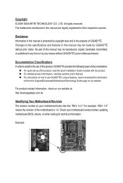
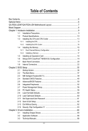
Advanced Mode...8 4. Configuring the Smart TPM Utility 18 4.1. Other Features...21 - 2 - Installing the Infineon TPM Driver 4 2.2. Installing the Smart TPM Utility 4 3. Initializing the TPM chip 5 3.1. Creating a Bluetooth Cell Phone Key 19 4.3. Initializing the TPM Chip with the Smart TPM Utility 5 3.2. Table of Contents TPM Configuration Procedure 3 1. Creating a USB Key 18 4.2. Configuring the System BIOS 3 2. Other Bluetooth Settings 21 4.4. Installing the Infineon TPM Driver and the Smart TPM Utility 4 2.1.
Advanced Mode...8 4. Configuring the Smart TPM Utility 18 4.1. Other Features...21 - 2 - Installing the Infineon TPM Driver 4 2.2. Installing the Smart TPM Utility 4 3. Initializing the TPM chip 5 3.1. Creating a Bluetooth Cell Phone Key 19 4.3. Initializing the TPM Chip with the Smart TPM Utility 5 3.2. Table of Contents TPM Configuration Procedure 3 1. Creating a USB Key 18 4.2. Configuring the System BIOS 3 2. Other Bluetooth Settings 21 4.4. Installing the Infineon TPM Driver and the Smart TPM Utility 4 2.1.

Manual
Page 3
...completing the settings, press to Enabled/Activate. To activate the TPM chip, set the User Password in the BIOS Setup program. - 3 - Step 1: As the computer starts, enter the BIOS Setup program. Be sure to activate the TPM chip. Initializing the TPM chip 4. Installing the Infineon TPM driver... and the Smart TPM utility 3. Configuring the System BIOS To use the Clear Security Chip setting (press + in sequence: 1. To prevent the TPM settings being cleared by other users, we recommend...
...completing the settings, press to Enabled/Activate. To activate the TPM chip, set the User Password in the BIOS Setup program. - 3 - Step 1: As the computer starts, enter the BIOS Setup program. Be sure to activate the TPM chip. Initializing the TPM chip 4. Installing the Infineon TPM driver... and the Smart TPM utility 3. Configuring the System BIOS To use the Clear Security Chip setting (press + in sequence: 1. To prevent the TPM settings being cleared by other users, we recommend...

Manual
Page 5
... Smart TPM icon and select Initialization Wizard to -use the "Secure e-mail" or "File and folder encryption - Initializing the TPM chip After configuring the system BIOS and installing the driver software, the Infineon Security Platform icon , which your Personal Secure Drive(PSD) Configure a Personal Secure Drive (PSD) here. Or you can...
... Smart TPM icon and select Initialization Wizard to -use the "Secure e-mail" or "File and folder encryption - Initializing the TPM chip After configuring the system BIOS and installing the driver software, the Infineon Security Platform icon , which your Personal Secure Drive(PSD) Configure a Personal Secure Drive (PSD) here. Or you can...

Manual
Page 6
... saving your Personal Secure Drive will be saved Select a local drive from the My PSD will be mapped to meet your own password in the BIOS Setup program. • This password incorporates the functionalities of the "Owner Password," "User Password," "Emergency Recovery Token Password," and "Password Reset Token Password" of the...
... saving your Personal Secure Drive will be saved Select a local drive from the My PSD will be mapped to meet your own password in the BIOS Setup program. • This password incorporates the functionalities of the "Owner Password," "User Password," "Emergency Recovery Token Password," and "Password Reset Token Password" of the...

Manual
Page 7
...Bluetooth enabled cell phone(s). If more than one USB flash drive at the same time. Enter a passkey (8~16 digits recommended) in the system BIOS. Then enter the same passkey on your phone. Before creating a Bluetooth cell phone key, make sure your motherboard includes a Bluetooth receiver and ... 3: Create Your Smart TPM Key 1. Create a Bluetooth cell phone key: Select the Use Bluetooth Device check box and click Refresh to BIOS check box will store the encrypted TPM User Password in Passkey which will be used for pairing. Then select the cell phone that you want...
...Bluetooth enabled cell phone(s). If more than one USB flash drive at the same time. Enter a passkey (8~16 digits recommended) in the system BIOS. Then enter the same passkey on your phone. Before creating a Bluetooth cell phone key, make sure your motherboard includes a Bluetooth receiver and ... 3: Create Your Smart TPM Key 1. Create a Bluetooth cell phone key: Select the Use Bluetooth Device check box and click Refresh to BIOS check box will store the encrypted TPM User Password in Passkey which will be used for pairing. Then select the cell phone that you want...

Manual
Page 18
...use software interface to launch the Smart TPM utility. In addition, users can access/close their encrypted TPM User Passwords in the BIOS, the latter will render the files encrypted via the TPM unable to be sure to store them in a secure location and ... connecting to display the menu as a result of complicated configurations. 4. Configuring the Smart TPM Utility GIGABYTE's unique Smart TPM (Trusted Platform Module) supports the industry's most advanced hardwarebased data encryption. GIGABYTE is not liable for loss of the password(s) or the key(s) will overwrite the former. - ...
...use software interface to launch the Smart TPM utility. In addition, users can access/close their encrypted TPM User Passwords in the BIOS, the latter will render the files encrypted via the TPM unable to be sure to store them in a secure location and ... connecting to display the menu as a result of complicated configurations. 4. Configuring the Smart TPM Utility GIGABYTE's unique Smart TPM (Trusted Platform Module) supports the industry's most advanced hardwarebased data encryption. GIGABYTE is not liable for loss of the password(s) or the key(s) will overwrite the former. - ...

Manual
Page 19
... the USB key, the Infineon Security Platform Settings Tool will be able to enter the password again, go to the "Security Chip Configuration" menu in BIOS Setup and then set earlier and click OK to use as the Smart TPM user key on your PSD by plugging in or unplugging the...
... the USB key, the Infineon Security Platform Settings Tool will be able to enter the password again, go to the "Security Chip Configuration" menu in BIOS Setup and then set earlier and click OK to use as the Smart TPM user key on your PSD by plugging in or unplugging the...
Manual
Page 3
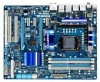
All rights reserved. No part of GIGABYTE. For detailed product information, carefully read or download the information on/from the Support&Downloads\Motherboard\Technology Guide page on your motherboard revision before updating motherboard BIOS, drivers, or when looking for technical information. ...REV: X.X." Copyright © 2009 GIGA-BYTE TECHNOLOGY CO., LTD. For product-related information, check on our website at: http://www.gigabyte.com.tw Identifying Your Motherboard Revision The revision number on our website. For example, "REV: 1.0" means the revision of the product,...
All rights reserved. No part of GIGABYTE. For detailed product information, carefully read or download the information on/from the Support&Downloads\Motherboard\Technology Guide page on your motherboard revision before updating motherboard BIOS, drivers, or when looking for technical information. ...REV: X.X." Copyright © 2009 GIGA-BYTE TECHNOLOGY CO., LTD. For product-related information, check on our website at: http://www.gigabyte.com.tw Identifying Your Motherboard Revision The revision number on our website. For example, "REV: 1.0" means the revision of the product,...
Manual
Page 4
Table of Contents Box Contents...6 Optional Items...6 GA-P55A-UD4P/GA-P55A-UD4 Motherboard Layout 7 Block Diagram...8 Chapter 1 Hardware Installation 9 1-1 Installation Precautions 9 1-2 Product Specifications 10 1-3 Installing the CPU and CPU Cooler ...;/NVIDIA SLI Configuration 19 1-7 Back Panel Connectors 20 1-8 Internal Connectors 22 Chapter 2 BIOS Setup 35 2-1 Startup Screen 36 2-2 The Main Menu 37 2-3 MB Intelligent Tweaker(M.I.T 39 2-4 Standard CMOS Features 48 2-5 Advanced BIOS Features 50 2-6 Integrated Peripherals 52 2-7 Power Management Setup 56 2-8 PC Health Status ...
Table of Contents Box Contents...6 Optional Items...6 GA-P55A-UD4P/GA-P55A-UD4 Motherboard Layout 7 Block Diagram...8 Chapter 1 Hardware Installation 9 1-1 Installation Precautions 9 1-2 Product Specifications 10 1-3 Installing the CPU and CPU Cooler ...;/NVIDIA SLI Configuration 19 1-7 Back Panel Connectors 20 1-8 Internal Connectors 22 Chapter 2 BIOS Setup 35 2-1 Startup Screen 36 2-2 The Main Menu 37 2-3 MB Intelligent Tweaker(M.I.T 39 2-4 Standard CMOS Features 48 2-5 Advanced BIOS Features 50 2-6 Integrated Peripherals 52 2-7 Power Management Setup 56 2-8 PC Health Status ...

Manual
Page 5
3-4 Contact...67 3-5 System...67 3-6 Download Center 68 3-7 New Utilities...68 Chapter 4 Unique Features 69 4-1 Xpress Recovery2 69 4-2 BIOS Update Utilities 72 4-2-1 Updating the BIOS with the Q-Flash Utility 72 4-2-2 Updating the BIOS with the @BIOS Utility 75 4-3 EasyTune 6...76 4-4 Dynamic Energy Saver™ 2 77 4-5 Q-Share...79 4-6 Smart 6™...80 4-7 Smart TPM j... Recording 126 5-2-5 Using the Sound Recorder 128 5-3 Troubleshooting 129 5-3-1 Frequently Asked Questions 129 5-3-2 Troubleshooting Procedure 130 5-4 Regulatory Statements 132 j Only for GA-P55A-UD4P. - 5 -
3-4 Contact...67 3-5 System...67 3-6 Download Center 68 3-7 New Utilities...68 Chapter 4 Unique Features 69 4-1 Xpress Recovery2 69 4-2 BIOS Update Utilities 72 4-2-1 Updating the BIOS with the Q-Flash Utility 72 4-2-2 Updating the BIOS with the @BIOS Utility 75 4-3 EasyTune 6...76 4-4 Dynamic Energy Saver™ 2 77 4-5 Q-Share...79 4-6 Smart 6™...80 4-7 Smart TPM j... Recording 126 5-2-5 Using the Sound Recorder 128 5-3 Troubleshooting 129 5-3-1 Frequently Asked Questions 129 5-3-2 Troubleshooting Procedure 130 5-4 Regulatory Statements 132 j Only for GA-P55A-UD4P. - 5 -
Manual
Page 8
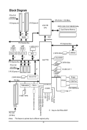
... Dual BIOS 6 SATA 3Gb/s 12 USB 2.0/1.1 LPC Bus IT8720 Floppy COM Port CODEC PS/2 KB/Mouse TPM j(Note) ATA-133/100/66/33 IDE Channel Surround Speaker Out Center/Subwoofer Speaker Out Side Speaker Out MIC Line Out Line In S/PDIF In S/PDIF Out 2 PCI PCI CLK (33 MHz) j Only for GA-P55A-UD4P...
... Dual BIOS 6 SATA 3Gb/s 12 USB 2.0/1.1 LPC Bus IT8720 Floppy COM Port CODEC PS/2 KB/Mouse TPM j(Note) ATA-133/100/66/33 IDE Channel Surround Speaker Out Center/Subwoofer Speaker Out Side Speaker Out MIC Line Out Line In S/PDIF In S/PDIF Out 2 PCI PCI CLK (33 MHz) j Only for GA-P55A-UD4P...
Manual
Page 12
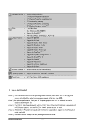
... on the CPU/system cooler you install. (Note 5) Available functions in EasyTune may differ by motherboard model. Hardware Monitor w w w w w w BIOS w w w w Unique Features w w w w w w w w w w w w w Bundled Software w System voltage detection CPU/System temperature...® Windows® 7/Vista/XP Form Factor w ATX Form Factor; 30.5cm x 24.4cm j Only for GA-P55A-UD4P. (Note 1) Due to Windows Vista/XP 32-bit operating system limitation, when more than 4 GB. (Note 2)...
... on the CPU/system cooler you install. (Note 5) Available functions in EasyTune may differ by motherboard model. Hardware Monitor w w w w w w BIOS w w w w Unique Features w w w w w w w w w w w w w Bundled Software w System voltage detection CPU/System temperature...® Windows® 7/Vista/XP Form Factor w ATX Form Factor; 30.5cm x 24.4cm j Only for GA-P55A-UD4P. (Note 1) Due to Windows Vista/XP 32-bit operating system limitation, when more than 4 GB. (Note 2)...
Manual
Page 16
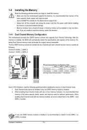
.... Dual Channel mode cannot be enabled if only one DDR3 memory module is installed, it is installed. 2. If you begin to GIGABYTE's website for optimum performance. Enabling Dual Channel memory mode will automatically detect the specifications and capacity of the same capacity, brand, speed...Always turn off the computer and unplug the power cord from the power outlet before installing the memory to install it is installed, the BIOS will double the original memory bandwidth. If only one DDR3 memory module is recommended to prevent hardware damage. • Memory modules have...
.... Dual Channel mode cannot be enabled if only one DDR3 memory module is installed, it is installed. 2. If you begin to GIGABYTE's website for optimum performance. Enabling Dual Channel memory mode will automatically detect the specifications and capacity of the same capacity, brand, speed...Always turn off the computer and unplug the power cord from the power outlet before installing the memory to install it is installed, the BIOS will double the original memory bandwidth. If only one DDR3 memory module is recommended to prevent hardware damage. • Memory modules have...
Manual
Page 18
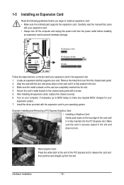
... your expansion card. • Always turn off the computer and unplug the power cord from the power outlet before you begin to make any required BIOS changes for your expansion card(s). 7. Make sure the card is securely seated in the slot. 3. Align the card with the slot, and press down on... slot. 1-5 Installing an Expansion Card Read the following guidelines before installing an expansion card to the chassis back panel with a screw. 5. If necessary, go to BIOS Setup to install an expansion card: • Make sure the motherboard supports the expansion card.
... your expansion card. • Always turn off the computer and unplug the power cord from the power outlet before you begin to make any required BIOS changes for your expansion card(s). 7. Make sure the card is securely seated in the slot. 3. Align the card with the slot, and press down on... slot. 1-5 Installing an Expansion Card Read the following guidelines before installing an expansion card to the chassis back panel with a screw. 5. If necessary, go to BIOS Setup to install an expansion card: • Make sure the motherboard supports the expansion card.

Manual
Page 27
...System Status LED Connects to the power switch on the chassis front panel. The LED is off when the system is detected, the BIOS may differ by issuing a beep code. This function requires a chassis with a chassis intrusion switch/sensor. When connecting your system using... the power switch (refer to Chapter 2, "BIOS Setup," "Power Management Setup," for information about beep codes. • HD (Hard Drive Activity LED, Blue) Connects to the reset switch on...
...System Status LED Connects to the power switch on the chassis front panel. The LED is off when the system is detected, the BIOS may differ by issuing a beep code. This function requires a chassis with a chassis intrusion switch/sensor. When connecting your system using... the power switch (refer to Chapter 2, "BIOS Setup," "Power Management Setup," for information about beep codes. • HD (Hard Drive Activity LED, Blue) Connects to the reset switch on...
Manual
Page 32
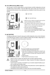
... may cause damage to the motherboard. • After system restart, go to BIOS Setup to load factory defaults (select Load Optimized Defaults) or manually configure the BIOS settings (refer to Chapter 2, "BIOS Setup," for BIOS configurations). 21) BAT (BATTERY) The battery provides power to keep the values...computer, be sure to replace the battery by removing the battery: 1. Plug in accordance with local environmental regulations. date information and BIOS configurations) and reset the CMOS values to clear the CMOS values (e.g. Replace the battery when the battery voltage drops to touch ...
... may cause damage to the motherboard. • After system restart, go to BIOS Setup to load factory defaults (select Load Optimized Defaults) or manually configure the BIOS settings (refer to Chapter 2, "BIOS Setup," for BIOS configurations). 21) BAT (BATTERY) The battery provides power to keep the values...computer, be sure to replace the battery by removing the battery: 1. Plug in accordance with local environmental regulations. date information and BIOS configurations) and reset the CMOS values to clear the CMOS values (e.g. Replace the battery when the battery voltage drops to touch ...
Manual
Page 35
... + in the main menu of the BIOS Setup program. To upgrade the BIOS, use either the GIGABYTE Q-Flash or @BIOS utility. • Q-Flash allows the user to quickly and easily upgrade or back up BIOS without entering the operating system. • @BIOS is potentially risky, if you not flash the BIOS. If this occurs, try to clear...
... + in the main menu of the BIOS Setup program. To upgrade the BIOS, use either the GIGABYTE Q-Flash or @BIOS utility. • Q-Flash allows the user to quickly and easily upgrade or back up BIOS without entering the operating system. • @BIOS is potentially risky, if you not flash the BIOS. If this occurs, try to clear...
Manual
Page 36
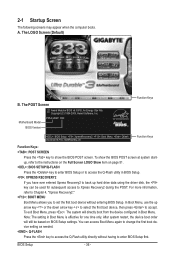
... screen at system startup, refer to the instructions on the Full Screen LOGO Show item on BIOS Setup settings. The LOGO Screen (Default) B. Motherboard Model BIOS Version P55A-UD4P D20 . . . . : BIOS Setup : XpressRecovery2 : Boot Menu : Qflash 09/23/2009-P55-7A89RG0WC-00 Function Keys Function Keys Function Keys: : POST SCREEN Press the key to accept...
... screen at system startup, refer to the instructions on the Full Screen LOGO Show item on BIOS Setup settings. The LOGO Screen (Default) B. Motherboard Model BIOS Version P55A-UD4P D20 . . . . : BIOS Setup : XpressRecovery2 : Boot Menu : Qflash 09/23/2009-P55-7A89RG0WC-00 Function Keys Function Keys Function Keys: : POST SCREEN Press the key to accept...
Manual
Page 37
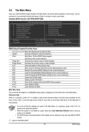
... Help) of function keys available for GA-P55A-UD4P. - 37 - Help for reference only and may differ by BIOS version. Use arrow keys to move among the items and press to accept or enter a sub-menu. (Sample BIOS Version: GA-P55A-UD4P D20) CMOS Setup Utility-Copyright (C) ...1984-2009 Award Software MB Intelligent Tweaker(M.I.T.) Standard CMOS Features Advanced BIOS Features Integrated Peripherals Power Management Setup ...
... Help) of function keys available for GA-P55A-UD4P. - 37 - Help for reference only and may differ by BIOS version. Use arrow keys to move among the items and press to accept or enter a sub-menu. (Sample BIOS Version: GA-P55A-UD4P D20) CMOS Setup Utility-Copyright (C) ...1984-2009 Award Software MB Intelligent Tweaker(M.I.T.) Standard CMOS Features Advanced BIOS Features Integrated Peripherals Power Management Setup ...


