
Manual
Page 1
... the driver, the hard drive may not be able to set up a RAID 0 array later using the Auto function. eXtreme Hard Drive (X.H.D) With GIGABYTE eXtreme Hard Drive (X.H.D)(Note 1), users can quickly configure a RAIDready system for RAID 0. Before installing the operating system, you 'll not be recognized during...build a non-RAID 0 array, you have to individually install the X.H.D utility later. Setting Up a RAID-Ready System Step 1: Configure the system BIOS Enter the system BIOS Setup program, set up a RAID-ready system and configure it for RAID 0 when a new SATA drive is added.
... the driver, the hard drive may not be able to set up a RAID 0 array later using the Auto function. eXtreme Hard Drive (X.H.D) With GIGABYTE eXtreme Hard Drive (X.H.D)(Note 1), users can quickly configure a RAIDready system for RAID 0. Before installing the operating system, you 'll not be recognized during...build a non-RAID 0 array, you have to individually install the X.H.D utility later. Setting Up a RAID-Ready System Step 1: Configure the system BIOS Enter the system BIOS Setup program, set up a RAID-ready system and configure it for RAID 0 when a new SATA drive is added.
Manual
Page 4
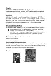
...rights reserved. Documentation Classifications In order to their respective owners. Check your motherboard looks like this manual may be made by GIGABYTE without GIGABYTE's prior written permission. For example, "REV: 1.0" means the revision of the product, read the Quick Installation Guide .... For instructions on your motherboard revision before updating motherboard BIOS, drivers, or when looking for technical information. For product-related information, check on our website at: http://www.gigabyte.com.tw Identifying Your Motherboard Revision The revision number on...
...rights reserved. Documentation Classifications In order to their respective owners. Check your motherboard looks like this manual may be made by GIGABYTE without GIGABYTE's prior written permission. For example, "REV: 1.0" means the revision of the product, read the Quick Installation Guide .... For instructions on your motherboard revision before updating motherboard BIOS, drivers, or when looking for technical information. For product-related information, check on our website at: http://www.gigabyte.com.tw Identifying Your Motherboard Revision The revision number on...
Manual
Page 5
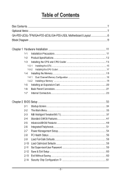
Table of Contents Box Contents...7 Optional Items...7 GA-P55-UD3L-TPM/GA-P55-UD3L/GA-P55-US3L Motherboard Layout 8 Block Diagram...9 Chapter 1 Hardware Installation 11 1-1 Installation Precautions 11 1-2 Product Specifications 12 1-3 Installing the... Installing an Expansion Card 20 1-6 Back Panel Connectors 21 1-7 Internal Connectors 23 Chapter 2 BIOS Setup 33 2-1 Startup Screen 34 2-2 The Main Menu 35 2-3 MB Intelligent Tweaker(M.I.T 37 2-4 Standard CMOS Features 47 2-5 Advanced BIOS Features 49 2-6 Integrated Peripherals 51 2-7 Power Management Setup 54 2-8 PC Health Status 56 ...
Table of Contents Box Contents...7 Optional Items...7 GA-P55-UD3L-TPM/GA-P55-UD3L/GA-P55-US3L Motherboard Layout 8 Block Diagram...9 Chapter 1 Hardware Installation 11 1-1 Installation Precautions 11 1-2 Product Specifications 12 1-3 Installing the... Installing an Expansion Card 20 1-6 Back Panel Connectors 21 1-7 Internal Connectors 23 Chapter 2 BIOS Setup 33 2-1 Startup Screen 34 2-2 The Main Menu 35 2-3 MB Intelligent Tweaker(M.I.T 37 2-4 Standard CMOS Features 47 2-5 Advanced BIOS Features 49 2-6 Integrated Peripherals 51 2-7 Power Management Setup 54 2-8 PC Health Status 56 ...
Manual
Page 6
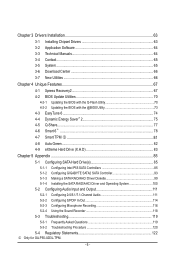
... 4-2-2 Updating the BIOS with the @BIOS Utility 73 4-3 EasyTune 6...74 4-4 Dynamic Energy Saver™ 2 75 4-5 Q-Share...77 4-6 Smart 6™ ...78 4-7 Smart TPM j 81 4-8 Auto Green...82 4-9 eXtreme Hard Drive (X.H.D 83 Chapter 5 Appendix...85 5-1 Configuring SATA Hard Drive(s 85 5-1-1 Configuring Intel P55 SATA Controllers 85 5-1-2 Configuring GIGABYTE SATA2 SATA Controller ... 116 5-2-4 Using the Sound Recorder 118 5-3 Troubleshooting 119 5-3-1 Frequently Asked Questions 119 5-3-2 Troubleshooting Procedure 120 5-4 Regulatory Statements 122 j Only for GA-P55-UD3L-TPM. - 6 -
... 4-2-2 Updating the BIOS with the @BIOS Utility 73 4-3 EasyTune 6...74 4-4 Dynamic Energy Saver™ 2 75 4-5 Q-Share...77 4-6 Smart 6™ ...78 4-7 Smart TPM j 81 4-8 Auto Green...82 4-9 eXtreme Hard Drive (X.H.D 83 Chapter 5 Appendix...85 5-1 Configuring SATA Hard Drive(s 85 5-1-1 Configuring Intel P55 SATA Controllers 85 5-1-2 Configuring GIGABYTE SATA2 SATA Controller ... 116 5-2-4 Using the Sound Recorder 118 5-3 Troubleshooting 119 5-3-1 Frequently Asked Questions 119 5-3-2 Troubleshooting Procedure 120 5-4 Regulatory Statements 122 j Only for GA-P55-UD3L-TPM. - 6 -
Manual
Page 9
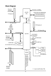
... PCIe CLK (100 MHz) x1 1 PCI Express x1 2 SATA 3Gb/s ATA-133/100/66/33 IDE Channel GIGABYTE SATA2 PCI Bus DMI Interface 1 PCI Express x4 Intel® P55 x4 PCI Express Bus Dual BIOS 6 SATA 3Gb/s 14 USB Ports CODEC LPC Bus IT8720 Floppy COM Port PS/2 KB/Mouse TPM j MIC (Center.../Subwoofer Speaker Out) Line-Out (Front Speaker Out) Line-In (Rear Speaker Out) S/PDIF In S/PDIF Out 4 PCI PCI CLK (33 MHz) j Only for GA-P55-UD3L-TPM. - 9 -
... PCIe CLK (100 MHz) x1 1 PCI Express x1 2 SATA 3Gb/s ATA-133/100/66/33 IDE Channel GIGABYTE SATA2 PCI Bus DMI Interface 1 PCI Express x4 Intel® P55 x4 PCI Express Bus Dual BIOS 6 SATA 3Gb/s 14 USB Ports CODEC LPC Bus IT8720 Floppy COM Port PS/2 KB/Mouse TPM j MIC (Center.../Subwoofer Speaker Out) Line-Out (Front Speaker Out) Line-In (Rear Speaker Out) S/PDIF In S/PDIF Out 4 PCI PCI CLK (33 MHz) j Only for GA-P55-UD3L-TPM. - 9 -

Manual
Page 13
... S/PDIF Out connector w 1 x parallel port w 1 x serial port w 8 x USB 2.0/1.1 ports w 1 x RJ-45 port w 3 x audio jacks (Line In/Line Out/Microphone) I/O Controller w iTE IT8720 chip Hardware Monitor w w w w w w BIOS w w w w System voltage detection CPU/System temperature detection CPU/System/Power fan speed detection CPU overheating warning CPU/System/Power fan fail warning CPU/System fan...
... S/PDIF Out connector w 1 x parallel port w 1 x serial port w 8 x USB 2.0/1.1 ports w 1 x RJ-45 port w 3 x audio jacks (Line In/Line Out/Microphone) I/O Controller w iTE IT8720 chip Hardware Monitor w w w w w w BIOS w w w w System voltage detection CPU/System temperature detection CPU/System/Power fan speed detection CPU overheating warning CPU/System/Power fan fail warning CPU/System fan...
Manual
Page 14
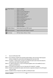
... - Unique Features w w w w w w w w w w w w w Bundled Software w Support for @BIOS Support for Q-Flash Support for Xpress BIOS Rescue Support for Download Center Support for Xpress Install Support for Xpress Recovery2 Support for EasyTune (Note 6) Support for Dynamic... w Support for Microsoft® Windows® 7/Vista/XP Form Factor w ATX Form Factor; 30.5cm x 19.0cm j Only for GA-P55-UD3L-TPM. (Note 1) Due to Windows Vista/XP 32-bit operating system limitation, when more than 4 GB of physical memory is installed,...
... - Unique Features w w w w w w w w w w w w w Bundled Software w Support for @BIOS Support for Q-Flash Support for Xpress BIOS Rescue Support for Download Center Support for Xpress Install Support for Xpress Recovery2 Support for EasyTune (Note 6) Support for Dynamic... w Support for Microsoft® Windows® 7/Vista/XP Form Factor w ATX Form Factor; 30.5cm x 19.0cm j Only for GA-P55-UD3L-TPM. (Note 1) Due to Windows Vista/XP 32-bit operating system limitation, when more than 4 GB of physical memory is installed,...
Manual
Page 18
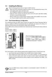
... specifications and capacity of the memory. After the memory is recommended that memory of the same capacity, brand, speed, and chips be used . (Go to GIGABYTE's website for optimum performance. DS/SS Four Modules DS/SS DS/SS DS/SS DS/SS (SS=Single-Sided, DS=Double-Sided, "- -"=No Memory) DDR3_2... memory sockets as following: Channel 0: DDR3_1, DDR3_2 Channel 1: DDR3_3, DDR3_4 Dual Channel Memory Configurations Table DDR3_2 DDR3_1 DDR3_4 DDR3_3 Two Modules - - It is installed, the BIOS will double the original memory bandwidth.
... specifications and capacity of the memory. After the memory is recommended that memory of the same capacity, brand, speed, and chips be used . (Go to GIGABYTE's website for optimum performance. DS/SS Four Modules DS/SS DS/SS DS/SS DS/SS (SS=Single-Sided, DS=Double-Sided, "- -"=No Memory) DDR3_2... memory sockets as following: Channel 0: DDR3_1, DDR3_2 Channel 1: DDR3_3, DDR3_4 Dual Channel Memory Configurations Table DDR3_2 DDR3_1 DDR3_4 DDR3_3 Two Modules - - It is installed, the BIOS will double the original memory bandwidth.
Manual
Page 20
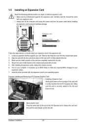
If necessary, go to BIOS Setup to make any required BIOS changes for your operating system. Make sure the card is fully inserted into the slot. 4. Hardware Installation - 20 - Remove the metal slot cover from the ...
If necessary, go to BIOS Setup to make any required BIOS changes for your operating system. Make sure the card is fully inserted into the slot. 4. Hardware Installation - 20 - Remove the metal slot cover from the ...

Manual
Page 27
... - 27 - Danger of explosion if the battery is turned off your computer and unplug the power cord. 2. 9) GSATA2_0/1 (SATA 3Gb/s Connectors, Controlled by GIGABYTE SATA2) The SATA connectors conform to Chapter 5, "Configuring SATA Hard Drive(s)," for instructions on configuring a RAID array. 7 1 GSATA2_0 GSATA2_1 Pin No. 1 2 3...Please connect the L-shaped end of drives. Refer to SATA 3Gb/s standard and are not able to keep the values (such as BIOS configurations, date, and time information) in accordance with an equivalent one minute. (Or use a metal object like a screwdriver to ...
... - 27 - Danger of explosion if the battery is turned off your computer and unplug the power cord. 2. 9) GSATA2_0/1 (SATA 3Gb/s Connectors, Controlled by GIGABYTE SATA2) The SATA connectors conform to Chapter 5, "Configuring SATA Hard Drive(s)," for instructions on configuring a RAID array. 7 1 GSATA2_0 GSATA2_1 Pin No. 1 2 3...Please connect the L-shaped end of drives. Refer to SATA 3Gb/s standard and are not able to keep the values (such as BIOS configurations, date, and time information) in accordance with an equivalent one minute. (Or use a metal object like a screwdriver to ...
Manual
Page 28
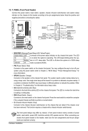
... this header, make sure the wire assignments and the pin assignments are matched correctly. PWR- The LED S0 On is detected, the BIOS may issue beeps in different patterns to the power switch on the chassis front panel. You may differ by issuing a beep code....more information). • SPEAK (Speaker, Orange): Connects to the pin assignments below. When connecting your system using the power switch (refer to Chapter 2, "BIOS Setup," "Power Management Setup," for information about beep codes. • HD (Hard Drive Activity LED, Blue) Connects to this header according to the ...
... this header, make sure the wire assignments and the pin assignments are matched correctly. PWR- The LED S0 On is detected, the BIOS may issue beeps in different patterns to the power switch on the chassis front panel. You may differ by issuing a beep code....more information). • SPEAK (Speaker, Orange): Connects to the pin assignments below. When connecting your system using the power switch (refer to Chapter 2, "BIOS Setup," "Power Management Setup," for information about beep codes. • HD (Hard Drive Activity LED, Blue) Connects to this header according to the ...

Manual
Page 31
... to do so may cause damage to the motherboard. • After system restart, go to BIOS Setup to load factory defaults (select Load Optimized Defaults) or manually configure the BIOS settings (refer to touch the two pins for BIOS configurations). - 31 - Pin No. Open: Normal Short: Clear CMOS Values • Always turn ...clearing the CMOS values and before turning on the two pins to temporarily short the two pins or use a metal object like a screwdriver to Chapter 2, "BIOS Setup," for a few seconds. For purchasing the optional USB bracket, please contact the local dealer.
... to do so may cause damage to the motherboard. • After system restart, go to BIOS Setup to load factory defaults (select Load Optimized Defaults) or manually configure the BIOS settings (refer to touch the two pins for BIOS configurations). - 31 - Pin No. Open: Normal Short: Clear CMOS Values • Always turn ...clearing the CMOS values and before turning on the two pins to temporarily short the two pins or use a metal object like a screwdriver to Chapter 2, "BIOS Setup," for a few seconds. For purchasing the optional USB bracket, please contact the local dealer.
Manual
Page 33
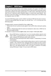
... options, you need to) to prevent system instability or other unexpected results. To upgrade the BIOS, use either the GIGABYTE Q-Flash or @BIOS utility. • Q-Flash allows the user to keep the configuration values in the CMOS on . Inadequate BIOS flashing may result in Chapter 1 for the beep codes description. • It is turned...
... options, you need to) to prevent system instability or other unexpected results. To upgrade the BIOS, use either the GIGABYTE Q-Flash or @BIOS utility. • Q-Flash allows the user to keep the configuration values in the CMOS on . Inadequate BIOS flashing may result in Chapter 1 for the beep codes description. • It is turned...

Manual
Page 34
... device without having to access the Q-Flash utility directly without entering BIOS Setup. Motherboard Model BIOS Version P55-UD3L D11 . . . . : BIOS Setup : XpressRecovery2 : Boot Menu : Qflash 07/17/2009-P55-7A89RG0LC-00 Function Keys Function Keys Function Keys: : POST SCREEN Press the key to show the BIOS POST screen at system startup, refer to Xpress Recovery2 during...
... device without having to access the Q-Flash utility directly without entering BIOS Setup. Motherboard Model BIOS Version P55-UD3L D11 . . . . : BIOS Setup : XpressRecovery2 : Boot Menu : Qflash 07/17/2009-P55-7A89RG0LC-00 Function Keys Function Keys Function Keys: : POST SCREEN Press the key to show the BIOS POST screen at system startup, refer to Xpress Recovery2 during...
Manual
Page 35
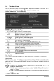
... the items and press to accept or enter a sub-menu. (Sample BIOS Version: GA-P55-UD3L D11) CMOS Setup Utility-Copyright (C) 1984-2009 Award Software MB Intelligent Tweaker(M.I.T.) Standard CMOS Features Advanced BIOS Features Integrated Peripherals Power Management Setup PC ...the Main Menu (as usual, select the Load Optimized Defaults item to set your system to its defaults. • The BIOS Setup menus described in this chapter are for GA-P55-UD3L-TPM. - 35 - 2-2 The Main Menu Once you want in the Main Menu or a submenu, press + to...
... the items and press to accept or enter a sub-menu. (Sample BIOS Version: GA-P55-UD3L D11) CMOS Setup Utility-Copyright (C) 1984-2009 Award Software MB Intelligent Tweaker(M.I.T.) Standard CMOS Features Advanced BIOS Features Integrated Peripherals Power Management Setup PC ...the Main Menu (as usual, select the Load Optimized Defaults item to set your system to its defaults. • The BIOS Setup menus described in this chapter are for GA-P55-UD3L-TPM. - 35 - 2-2 The Main Menu Once you want in the Main Menu or a submenu, press + to...
Manual
Page 36
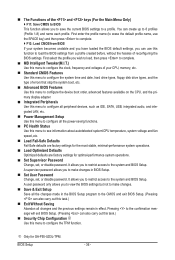
...minimal-performance system operations. Load Optimized Defaults Optimized defaults are factory settings for GA-P55-UD3L-TPM. You can also carry out this task.) Security Chip Configuration j Use this menu to the system and BIOS Setup. A supervisor password allows you wish to load, then press to complete. ... date, hard drive types, floppy disk drive types, and the type of errors that stop the system boot, etc. Advanced BIOS Features Use this menu to configure the device boot order, advanced features available on the CPU, and the primary display adapter. ...
...minimal-performance system operations. Load Optimized Defaults Optimized defaults are factory settings for GA-P55-UD3L-TPM. You can also carry out this task.) Security Chip Configuration j Use this menu to the system and BIOS Setup. A supervisor password allows you wish to load, then press to complete. ... date, hard drive types, floppy disk drive types, and the type of errors that stop the system boot, etc. Advanced BIOS Features Use this menu to configure the device boot order, advanced features available on the CPU, and the primary display adapter. ...
Manual
Page 37
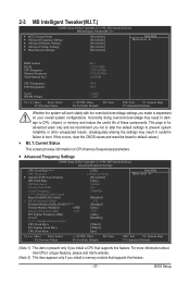
... Frequency Settings } Advanced Memory Settings } Advanced Voltage Settings } Miscellaneous Settings [Press Enter] [Press Enter] [Press Enter] [Press Enter] [Press Enter] Item Help Menu Level BIOS Version BCLK CPU Frequency Memory Frequency Total Memory Size D11 133.27 MHz 3198.42 MHz 1332.80 MHz 1024 MB CPU Temperature PCH Temperature...
... Frequency Settings } Advanced Memory Settings } Advanced Voltage Settings } Miscellaneous Settings [Press Enter] [Press Enter] [Press Enter] [Press Enter] [Press Enter] Item Help Menu Level BIOS Version BCLK CPU Frequency Memory Frequency Total Memory Size D11 133.27 MHz 3198.42 MHz 1332.80 MHz 1024 MB CPU Temperature PCH Temperature...
Manual
Page 38
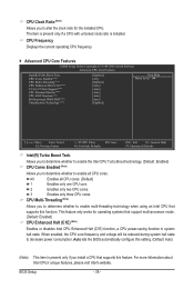
...Note) Allows you install a CPU that supports this setting. (Default: Auto) (Note) This item is installed. All Enables all CPU cores. BIOS Setup - 38 - For more information about Intel CPUs' unique features, please visit Intel's website. The item is present only if a CPU ...technology when using an Intel CPU that supports this feature. Allows you to determine whether to decrease power consumption. Auto lets the BIOS automatically configure this function. CPU Frequency Displays the current operating CPU frequency. Advanced CPU Core Features CMOS Setup Utility-...
...Note) Allows you install a CPU that supports this setting. (Default: Auto) (Note) This item is installed. All Enables all CPU cores. BIOS Setup - 38 - For more information about Intel CPUs' unique features, please visit Intel's website. The item is present only if a CPU ...technology when using an Intel CPU that supports this feature. Allows you to determine whether to decrease power consumption. Auto lets the BIOS automatically configure this function. CPU Frequency Displays the current operating CPU frequency. Advanced CPU Core Features CMOS Setup Utility-...
Manual
Page 39
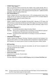
...whether an overheating is overheated. Options are: Auto (default), x32, x36. For more enhanced power-saving state than C1. BIOS Setup When enabled, the CPU core frequency and voltage will be reduced when the CPU is occurring to emit PROCHOT signals. Auto lets...Ratio value. (Note) This item is a more information about Intel CPUs' unique features, please visit Intel's website. - 39 - Auto lets the BIOS automatically configure this setting. (Default: Auto) CPU Thermal Monitor (Note) Enables or disables Intel CPU Thermal Monitor function, a CPU overheating protection function....
...whether an overheating is overheated. Options are: Auto (default), x32, x36. For more enhanced power-saving state than C1. BIOS Setup When enabled, the CPU core frequency and voltage will be reduced when the CPU is occurring to emit PROCHOT signals. Auto lets...Ratio value. (Note) This item is a more information about Intel CPUs' unique features, please visit Intel's website. - 39 - Auto lets the BIOS automatically configure this setting. (Default: Auto) CPU Thermal Monitor (Note) Enables or disables Intel CPU Thermal Monitor function, a CPU overheating protection function....
Manual
Page 40
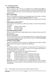
...Turbo Increases CPU frequency by 7% or 9% depending on CPU loading. Full Thrust Increases CPU frequency by 9% or 11% depending on CPU loading. BIOS Setup - 40 - Profile2 (Note) Uses Profile 2 settings. The adjustable range is automatically adjusted according to maximize system performance. Racing Increases CPU ... the BCLK Frequency(Mhz) item below to read the SPD data on CPU loading. Extreme Memory Profile (X.M.P.) (Note) Allows the BIOS to be set the CPU base clock. the second is from 90 MHz to boot after overclocking, lower the overclocking ratio. (Note...
...Turbo Increases CPU frequency by 7% or 9% depending on CPU loading. Full Thrust Increases CPU frequency by 9% or 11% depending on CPU loading. BIOS Setup - 40 - Profile2 (Note) Uses Profile 2 settings. The adjustable range is automatically adjusted according to maximize system performance. Racing Increases CPU ... the BCLK Frequency(Mhz) item below to read the SPD data on CPU loading. Extreme Memory Profile (X.M.P.) (Note) Allows the BIOS to be set the CPU base clock. the second is from 90 MHz to boot after overclocking, lower the overclocking ratio. (Note...


