
Manual
Page 1
... 3: Install the motherboard drivers and the X.H.D utiltiy After installing the operating system, insert the motherboard driver disk. Exits the X.H.D utility: Click Cancel to exit the X.H.D utility. (Note 1) The X.H.D utility only supports the SATA controllers integrated in the array. ) 1. Step 2: Install the RAID driver and operating system The X.H.D utility supports Windows 7/Vista/XP. To manually set eXtreme Hard Drive (X.H.D) under the Integrated Peripherals menu to Enabled to enable RAID for complex and time-consuming configurations. B. Using GIGABYTE eXtreme Hard Drive...
... 3: Install the motherboard drivers and the X.H.D utiltiy After installing the operating system, insert the motherboard driver disk. Exits the X.H.D utility: Click Cancel to exit the X.H.D utility. (Note 1) The X.H.D utility only supports the SATA controllers integrated in the array. ) 1. Step 2: Install the RAID driver and operating system The X.H.D utility supports Windows 7/Vista/XP. To manually set eXtreme Hard Drive (X.H.D) under the Integrated Peripherals menu to Enabled to enable RAID for complex and time-consuming configurations. B. Using GIGABYTE eXtreme Hard Drive...
Manual
Page 4
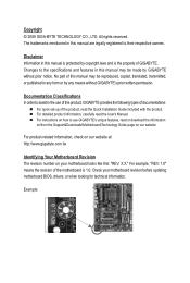
..., carefully read or download the information on/from the Support&Downloads\Motherboard\Technology Guide page on our website. Changes to their respective owners. Documentation Classifications In order to use of this product, GIGABYTE provides the following types of documentations: For quick set-up of the product, read the Quick Installation Guide included with the product. Check your motherboard looks like this manual is protected by...
..., carefully read or download the information on/from the Support&Downloads\Motherboard\Technology Guide page on our website. Changes to their respective owners. Documentation Classifications In order to use of this product, GIGABYTE provides the following types of documentations: For quick set-up of the product, read the Quick Installation Guide included with the product. Check your motherboard looks like this manual is protected by...
Manual
Page 5
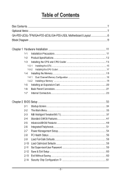
... Box Contents...7 Optional Items...7 GA-P55-UD3L-TPM/GA-P55-UD3L/GA-P55-US3L Motherboard Layout 8 Block Diagram...9 Chapter 1 Hardware Installation 11 1-1 Installation Precautions 11 1-2 Product Specifications 12 1-3 Installing the CPU and CPU Cooler 15 1-3-1 Installing the CPU 15 1-3-2 Installing the CPU Cooler 17 1-4 Installing the Memory 18 1-4-1 Dual Channel Memory Configuration 18 1-4-2 Installing a Memory 19 1-5 Installing an Expansion Card 20 1-6 Back Panel Connectors 21 1-7 Internal Connectors 23 Chapter 2 BIOS Setup 33 2-1 Startup Screen 34 2-2 The Main Menu 35 2-3 MB...
... Box Contents...7 Optional Items...7 GA-P55-UD3L-TPM/GA-P55-UD3L/GA-P55-US3L Motherboard Layout 8 Block Diagram...9 Chapter 1 Hardware Installation 11 1-1 Installation Precautions 11 1-2 Product Specifications 12 1-3 Installing the CPU and CPU Cooler 15 1-3-1 Installing the CPU 15 1-3-2 Installing the CPU Cooler 17 1-4 Installing the Memory 18 1-4-1 Dual Channel Memory Configuration 18 1-4-2 Installing a Memory 19 1-5 Installing an Expansion Card 20 1-6 Back Panel Connectors 21 1-7 Internal Connectors 23 Chapter 2 BIOS Setup 33 2-1 Startup Screen 34 2-2 The Main Menu 35 2-3 MB...
Manual
Page 12
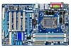
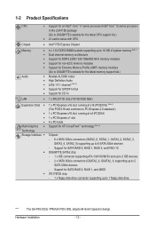
.... Support for SATA RAID 0, RAID 1, RAID 5, and RAID 10 GIGABYTE SATA2 chip: - 1 x IDE connector supporting ATA-133/100/66/33 and up to 2 IDE devices - 2 x SATA 3Gb/s connectors (GSATA2_0, GSATA2_1) supporting up to 6 SATA 3Gb/s devices - 1-2 Product Specifications CPU Support for an Intel® Core™ i7 series processor/Intel® Core™ i5 series processor in the LGA1156 package (Go to GIGABYTE's website for the latest CPU support list.) L3 cache varies with CPU Chipset Intel® P55 Express Chipset Memory Audio...
.... Support for SATA RAID 0, RAID 1, RAID 5, and RAID 10 GIGABYTE SATA2 chip: - 1 x IDE connector supporting ATA-133/100/66/33 and up to 2 IDE devices - 2 x SATA 3Gb/s connectors (GSATA2_0, GSATA2_1) supporting up to 6 SATA 3Gb/s devices - 1-2 Product Specifications CPU Support for an Intel® Core™ i7 series processor/Intel® Core™ i5 series processor in the LGA1156 package (Go to GIGABYTE's website for the latest CPU support list.) L3 cache varies with CPU Chipset Intel® P55 Express Chipset Memory Audio...

Manual
Page 31
... two pins for BIOS configurations). - 31 - To clear the CMOS values, place a jumper cap on your computer and unplug the power cord from the jumper. Failure to do so may cause damage to the motherboard. • After system restart, go to BIOS Setup to load factory defaults (select Load Optimized Defaults) or manually configure the BIOS settings (refer to clear the CMOS values (e.g. Hardware Installation date information and BIOS configurations) and reset the CMOS values to USB 2.0/1.1 specification. 16...
... two pins for BIOS configurations). - 31 - To clear the CMOS values, place a jumper cap on your computer and unplug the power cord from the jumper. Failure to do so may cause damage to the motherboard. • After system restart, go to BIOS Setup to load factory defaults (select Load Optimized Defaults) or manually configure the BIOS settings (refer to clear the CMOS values (e.g. Hardware Installation date information and BIOS configurations) and reset the CMOS values to USB 2.0/1.1 specification. 16...

Manual
Page 34
... used for one time only. Motherboard Model BIOS Version P55-UD3L D11 . . . . : BIOS Setup : XpressRecovery2 : Boot Menu : Qflash 07/17/2009-P55-7A89RG0LC-00 Function Keys Function Keys Function Keys: : POST SCREEN Press the key to show the BIOS POST screen at system startup, refer to Xpress Recovery2 during the POST. To exit Boot Menu, press . In Boot Menu, use the up hard drive data using the driver disk, the key can access Boot Menu again to change the first boot device setting as needed. : Q-FLASH Press the key to access the Q-Flash utility in Boot Menu...
... used for one time only. Motherboard Model BIOS Version P55-UD3L D11 . . . . : BIOS Setup : XpressRecovery2 : Boot Menu : Qflash 07/17/2009-P55-7A89RG0LC-00 Function Keys Function Keys Function Keys: : POST SCREEN Press the key to show the BIOS POST screen at system startup, refer to Xpress Recovery2 during the POST. To exit Boot Menu, press . In Boot Menu, use the up hard drive data using the driver disk, the key can access Boot Menu again to change the first boot device setting as needed. : Q-FLASH Press the key to access the Q-Flash utility in Boot Menu...
Manual
Page 36
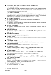
... CPU, memory, etc. Standard CMOS Features Use this menu to configure the system time and date, hard drive types, floppy disk drive types, and the type of errors that stop the system boot, etc. Advanced BIOS Features Use this menu to configure the device boot order, advanced features available on the CPU, and the primary display adapter. Integrated Peripherals Use this menu to configure all peripheral devices, such as IDE, SATA, USB, integrated audio, and integrated LAN, etc. Power Management Setup Use...
... CPU, memory, etc. Standard CMOS Features Use this menu to configure the system time and date, hard drive types, floppy disk drive types, and the type of errors that stop the system boot, etc. Advanced BIOS Features Use this menu to configure the device boot order, advanced features available on the CPU, and the primary display adapter. Integrated Peripherals Use this menu to configure all peripheral devices, such as IDE, SATA, USB, integrated audio, and integrated LAN, etc. Power Management Setup Use...
Manual
Page 39
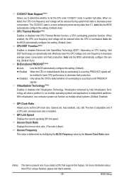
... CPU loading, Intel EIST technology can function as multiple virtual systems. (Default: Enabled) QPI Clock Ratio Allows you to determine whether to let the CPU enter C3/C6/C7 mode in independent partitions. Auto lets the BIOS automatically configure this setting. (Default: Auto) Bi-Directional PROCHOT (Note) Auto Lets the BIOS automatically configure this setting. (Default) Enabled When the CPU or chipset detects that supports this feature. C3/C6/C7 State Support (Note) Allows you to set...
... CPU loading, Intel EIST technology can function as multiple virtual systems. (Default: Enabled) QPI Clock Ratio Allows you to determine whether to let the CPU enter C3/C6/C7 mode in independent partitions. Auto lets the BIOS automatically configure this setting. (Default: Auto) Bi-Directional PROCHOT (Note) Auto Lets the BIOS automatically configure this setting. (Default) Enabled When the CPU or chipset detects that supports this feature. C3/C6/C7 State Support (Note) Allows you to set...
Manual
Page 46
... the CPU and Chipset. (Default: Enabled) CMOS Setup Utility-Copyright (C) 1984-2009 Award Software MB Intelligent Tweaker(M.I.T.) } M.I.T Current Status } Advanced Frequency Settings } Advanced Memory Settings } Advanced Voltage Settings } Miscellaneous Settings [Press Enter] [Press Enter] [Press Enter] [Press Enter] [Press Enter] Item Help Menu Level BIOS Version BCLK CPU Frequency Memory Frequency Total Memory Size D11 133.27 MHz 3198.42 MHz 1332.80 MHz 1024 MB CPU Temperature PCH Temperature 45oC 40oC Vcore DRAM Voltage...
... the CPU and Chipset. (Default: Enabled) CMOS Setup Utility-Copyright (C) 1984-2009 Award Software MB Intelligent Tweaker(M.I.T.) } M.I.T Current Status } Advanced Frequency Settings } Advanced Memory Settings } Advanced Voltage Settings } Miscellaneous Settings [Press Enter] [Press Enter] [Press Enter] [Press Enter] [Press Enter] Item Help Menu Level BIOS Version BCLK CPU Frequency Memory Frequency Total Memory Size D11 133.27 MHz 3198.42 MHz 1332.80 MHz 1024 MB CPU Temperature PCH Temperature 45oC 40oC Vcore DRAM Voltage...
Manual
Page 49
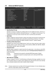
... key to select a device and press to deliver greater efficiency for daily use. Options are: Floppy, LS120, Hard Disk, CDROM, ZIP, USB-FDD, USB-ZIP, USB-CDROM, USB-HDD, Legacy LAN, Disabled. Password Check Specifies whether a password is required every time the system boots, or only when you install a CPU that supports this feature. BIOS Setup Use the up process to shorten the waiting time for entering the operating system and to accept. After configuring this menu...
... key to select a device and press to deliver greater efficiency for daily use. Options are: Floppy, LS120, Hard Disk, CDROM, ZIP, USB-FDD, USB-ZIP, USB-CDROM, USB-HDD, Legacy LAN, Disabled. Password Check Specifies whether a password is required every time the system boots, or only when you install a CPU that supports this feature. BIOS Setup Use the up process to shorten the waiting time for entering the operating system and to accept. After configuring this menu...
Manual
Page 51
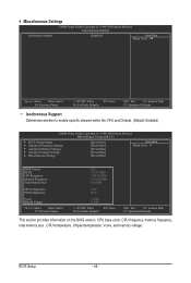
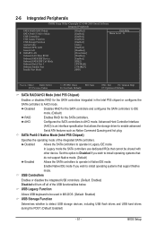
... Legacy IDE mode. USB Legacy Function Allows USB keyboard to AHCI mode. 2-6 Integrated Peripherals CMOS Setup Utility-Copyright (C) 1984-2009 Award Software Integrated Peripherals SATA RAID/AHCI Mode SATA Port0-3 Native Mode USB Controllers USB Legacy Function USB Storage Function Azalia Codec Onboard H/W LAN Green LAN } SMART LAN Onboard LAN Boot ROM Onboard SATA/IDE Device Onboard SATA/IDE Ctrl Mode Onboard Serial Port 1 Onboard Parallel Port Parallel Port Mode [Disabled] [Enabled] [Enabled] [Enabled] [Enabled] [Auto] [Enabled] [Disabled...
... Legacy IDE mode. USB Legacy Function Allows USB keyboard to AHCI mode. 2-6 Integrated Peripherals CMOS Setup Utility-Copyright (C) 1984-2009 Award Software Integrated Peripherals SATA RAID/AHCI Mode SATA Port0-3 Native Mode USB Controllers USB Legacy Function USB Storage Function Azalia Codec Onboard H/W LAN Green LAN } SMART LAN Onboard LAN Boot ROM Onboard SATA/IDE Device Onboard SATA/IDE Ctrl Mode Onboard Serial Port 1 Onboard Parallel Port Parallel Port Mode [Disabled] [Enabled] [Enabled] [Enabled] [Enabled] [Auto] [Enabled] [Disabled...
Manual
Page 53
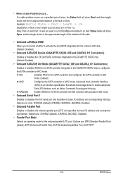
... the onboard LAN chip. (Default: Disabled) Onboard SATA/IDE Device (GIGABYTE SATA2, IDE and GSATA2_0/1 Connectors) Enables or disables the IDE and SATA controllers integrated in the GIGABYTE SATA2 chip. (Default: Enabled) Onboard SATA/IDE Ctrl Mode (GIGABYTE SATA2, IDE and GSATA2_0/1 Connectors) Enables or disables RAID for the onboard parallel (LPT) port. When a Cable Problem Occurs... RAID/IDE Enables RAID for the SATA controller and configures the SATA controller to IDE mode. (Default) AHCI Configures the SATA controller to the fault or short. Options are : Auto, 3F8...
... the onboard LAN chip. (Default: Disabled) Onboard SATA/IDE Device (GIGABYTE SATA2, IDE and GSATA2_0/1 Connectors) Enables or disables the IDE and SATA controllers integrated in the GIGABYTE SATA2 chip. (Default: Enabled) Onboard SATA/IDE Ctrl Mode (GIGABYTE SATA2, IDE and GSATA2_0/1 Connectors) Enables or disables RAID for the onboard parallel (LPT) port. When a Cable Problem Occurs... RAID/IDE Enables RAID for the SATA controller and configures the SATA controller to IDE mode. (Default) AHCI Configures the SATA controller to the fault or short. Options are : Auto, 3F8...
Manual
Page 56
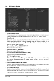
... CPU temperature exceeds the threshold, BIOS will show "No" at next boot. (Default: Disabled) Case Opened Displays the detection status of the chassis intrusion detection device attached to the motherboard CI header. You can adjust the fan speed with EasyTune based on system requirements. Enabled allows the CPU fan to emit warning sound if the CPU/system/power fan is removed, this occurs. (Default: Disabled) CPU Smart FAN Control Enables or disables the CPU fan speed control function. Enabled clears the record of previous chassis intrusion status. CPU...
... CPU temperature exceeds the threshold, BIOS will show "No" at next boot. (Default: Disabled) Case Opened Displays the detection status of the chassis intrusion detection device attached to the motherboard CI header. You can adjust the fan speed with EasyTune based on system requirements. Enabled allows the CPU fan to emit warning sound if the CPU/system/power fan is removed, this occurs. (Default: Disabled) CPU Smart FAN Control Enables or disables the CPU fan speed control function. Enabled clears the record of previous chassis intrusion status. CPU...
Manual
Page 81
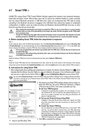
... Clear Security Chip setting (press + in the BIOS main menu to display this password because it to store them in the system BIOS. j Only for using a Bluetooth cell phone or USB flash drive. Unique Features GIGABYTE is not liable for loss of the autorun screen and you set up a Personal Secure Drive (PSD). Before installing Smart TPM, follow the steps below in the BIOS Setup program. Step 3: Install the Smart TPM utility from the motherboard driver disk...
... Clear Security Chip setting (press + in the BIOS main menu to display this password because it to store them in the system BIOS. j Only for using a Bluetooth cell phone or USB flash drive. Unique Features GIGABYTE is not liable for loss of the autorun screen and you set up a Personal Secure Drive (PSD). Before installing Smart TPM, follow the steps below in the BIOS Setup program. Step 3: Install the Smart TPM utility from the motherboard driver disk...

Manual
Page 83
... Application Software screen to automatically set up a RAID-ready system and configure it for RAID 0. Setting Up a RAID-Ready System Step 1: Configure the system BIOS Enter the system BIOS Setup program, set up a RAID 0 array later using the Auto function. - 83 - Step 2: Install the RAID driver and operating system The X.H.D utility supports Windows 7/Vista/XP. Without the driver, the hard drive may not be able to individually install the X.H.D utility later. Exits the X.H.D utility: Click Cancel to load the SATA controller driver first...
... Application Software screen to automatically set up a RAID-ready system and configure it for RAID 0. Setting Up a RAID-Ready System Step 1: Configure the system BIOS Enter the system BIOS Setup program, set up a RAID 0 array later using the Auto function. - 83 - Step 2: Install the RAID driver and operating system The X.H.D utility supports Windows 7/Vista/XP. Without the driver, the hard drive may not be able to individually install the X.H.D utility later. Exits the X.H.D utility: Click Cancel to load the SATA controller driver first...
Manual
Page 86
...Setup Utility-Copyright (C) 1984-2009 Award Software Integrated Peripherals SATA RAID/AHCI Mode SATA Port0-3 Native Mode USB Controllers USB Legacy Function USB Storage Function Azalia Codec Onboard H/W LAN Green LAN } SMART LAN Onboard LAN Boot ROM Onboard SATA/IDE Device Onboard SATA/IDE Ctrl Mode Onboard Serial Port 1 Onboard Parallel Port Parallel Port Mode [RAID] [Enabled] [Enabled] [Enabled] [Enabled] [Auto] [Enabled] [Disabled] [Press Enter] [Disabled] [Enabled] [IDE] [3F8/IRQ4] [378/IRQ7] [SPP] Item Help Menu Level Move Enter...
...Setup Utility-Copyright (C) 1984-2009 Award Software Integrated Peripherals SATA RAID/AHCI Mode SATA Port0-3 Native Mode USB Controllers USB Legacy Function USB Storage Function Azalia Codec Onboard H/W LAN Green LAN } SMART LAN Onboard LAN Boot ROM Onboard SATA/IDE Device Onboard SATA/IDE Ctrl Mode Onboard Serial Port 1 Onboard Parallel Port Parallel Port Mode [RAID] [Enabled] [Enabled] [Enabled] [Enabled] [Auto] [Enabled] [Disabled] [Press Enter] [Disabled] [Enabled] [IDE] [3F8/IRQ4] [378/IRQ7] [SPP] Item Help Menu Level Move Enter...
Manual
Page 93
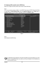
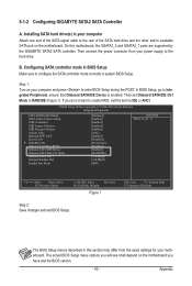
... POST. Then connect the power connector from the exact settings for your computer and press to Integrated Peripherals, ensure that Onboard SATA/IDE Device is enabled. 5-1-2 Configuring GIGABYTE SATA2 SATA Controller A. CMOS Setup Utility-Copyright (C) 1984-2009 Award Software Integrated Peripherals SATA RAID/AHCI Mode SATA Port0-3 Native Mode USB Controllers USB Legacy Function USB Storage Function Azalia Codec Onboard H/W LAN Green LAN } SMART LAN Onboard LAN Boot ROM Onboard SATA/IDE Device Onboard SATA/IDE Ctrl Mode Onboard Serial Port...
... POST. Then connect the power connector from the exact settings for your computer and press to Integrated Peripherals, ensure that Onboard SATA/IDE Device is enabled. 5-1-2 Configuring GIGABYTE SATA2 SATA Controller A. CMOS Setup Utility-Copyright (C) 1984-2009 Award Software Integrated Peripherals SATA RAID/AHCI Mode SATA Port0-3 Native Mode USB Controllers USB Legacy Function USB Storage Function Azalia Codec Onboard H/W LAN Green LAN } SMART LAN Onboard LAN Boot ROM Onboard SATA/IDE Device Onboard SATA/IDE Ctrl Mode Onboard Serial Port...

Manual
Page 99
..., from the motherboard driver disk to a USB flash drive. 5-1-3 Making a SATA RAID/AHCI Driver Diskette (Required for AHCI and RAID Mode) To successfully install operating system onto SATA hard drive(s) that is D:\). 3: At the A:\> prompt, type the following command. For installing Windows Vista, you also can copy the SATA controller driver from the menu in Figure 4. 3: Insert the blank formatted disk. Steps: 1: Boot from \32bit to \64bit if you need to install the SATA controller driver during the Windows setup process. See...
..., from the motherboard driver disk to a USB flash drive. 5-1-3 Making a SATA RAID/AHCI Driver Diskette (Required for AHCI and RAID Mode) To successfully install operating system onto SATA hard drive(s) that is D:\). 3: At the A:\> prompt, type the following command. For installing Windows Vista, you also can copy the SATA controller driver from the menu in Figure 4. 3: Insert the blank formatted disk. Steps: 1: Boot from \32bit to \64bit if you need to install the SATA controller driver during the Windows setup process. See...
Manual
Page 101
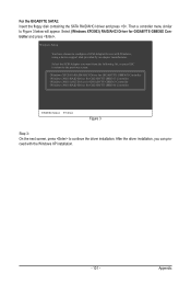
... you can proceed with Windows, using a device support disk provided by an adapter manufacturer. Then a controller menu similar to configure a SCSI Adapter for use with the Windows XP installation. - 101 - Windows Setup You have chosen to Figure 3 below will appear. Select (Windows XP/2003) RAID/AHCI Driver for GIGABYTE GBB360 Controller ENTER=Select F3=Exit Figure 3 Step 3: On the next screen, press to continue the driver installation. After the driver installation, you want from the...
... you can proceed with Windows, using a device support disk provided by an adapter manufacturer. Then a controller menu similar to configure a SCSI Adapter for use with the Windows XP installation. - 101 - Windows Setup You have chosen to Figure 3 below will appear. Select (Windows XP/2003) RAID/AHCI Driver for GIGABYTE GBB360 Controller ENTER=Select F3=Exit Figure 3 Step 3: On the next screen, press to continue the driver installation. After the driver installation, you want from the...
Manual
Page 119
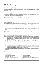
... install the onboard HD audio driver from the motherboard driver disk or download the audio driver from GIGABYTE's website to show the advanced options. A: The following Award BIOS beep code descriptions may help you identify possible computer problems. (For reference only.) 1 short: System boots successfully 1 long, 3 short: Keyboard error 2 short: CMOS setting error 1 long, 9 short: BIOS ROM error 1 long, 1 short: Memory or motherboard error Continuous long beeps: Graphics card not inserted properly 1 long, 2 short: Monitor or graphics card error Continuous short beeps: Power error...
... install the onboard HD audio driver from the motherboard driver disk or download the audio driver from GIGABYTE's website to show the advanced options. A: The following Award BIOS beep code descriptions may help you identify possible computer problems. (For reference only.) 1 short: System boots successfully 1 long, 3 short: Keyboard error 2 short: CMOS setting error 1 long, 9 short: BIOS ROM error 1 long, 1 short: Memory or motherboard error Continuous long beeps: Graphics card not inserted properly 1 long, 2 short: Monitor or graphics card error Continuous short beeps: Power error...


