
Manual
Page 1
... function. Or you can build a RAID 0, RAID 1, or other supported RAID array depending on your needs and hardware components. 3. A. To manually set up a RAID 0 array. 2. Setting Up a RAID-Ready System Step 1: Configure the system BIOS Enter the system BIOS Setup program, ... System." ) Step 3: Install the motherboard drivers and the X.H.D utiltiy After installing the operating system, insert the motherboard driver disk. Using GIGABYTE eXtreme Hard Drive (X.H.D) Instructions:(Note 2) Before launching X.H.D, make sure the new drive is added. To automatically set up a RAID 0 ...
... function. Or you can build a RAID 0, RAID 1, or other supported RAID array depending on your needs and hardware components. 3. A. To manually set up a RAID 0 array. 2. Setting Up a RAID-Ready System Step 1: Configure the system BIOS Enter the system BIOS Setup program, ... System." ) Step 3: Install the motherboard drivers and the X.H.D utiltiy After installing the operating system, insert the motherboard driver disk. Using GIGABYTE eXtreme Hard Drive (X.H.D) Instructions:(Note 2) Before launching X.H.D, make sure the new drive is added. To automatically set up a RAID 0 ...
Manual
Page 1
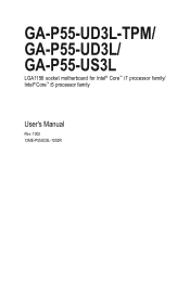
GA-P55-UD3L-TPM/ GA-P55-UD3L/ GA-P55-US3L LGA1156 socket motherboard for Intel® Core™ i7 processor family/ Intel® Core™ i5 processor family User's Manual Rev. 1002 12ME-P55UD3L-1002R
GA-P55-UD3L-TPM/ GA-P55-UD3L/ GA-P55-US3L LGA1156 socket motherboard for Intel® Core™ i7 processor family/ Intel® Core™ i5 processor family User's Manual Rev. 1002 12ME-P55UD3L-1002R
Manual
Page 4
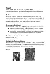
Changes to assist in any means without prior notice. Documentation Classifications In order to the specifications and features in this manual may be made by GIGABYTE without GIGABYTE's prior written permission. For detailed product information, carefully read or download the information on/from the Support&Downloads\Motherboard\Technology Guide page on your motherboard ...
Changes to assist in any means without prior notice. Documentation Classifications In order to the specifications and features in this manual may be made by GIGABYTE without GIGABYTE's prior written permission. For detailed product information, carefully read or download the information on/from the Support&Downloads\Motherboard\Technology Guide page on your motherboard ...
Manual
Page 6
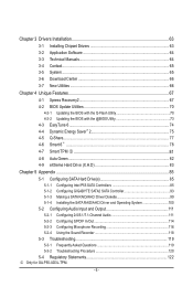
... Drivers Installation 63 3-1 Installing Chipset Drivers 63 3-2 Application Software 64 3-3 Technical Manuals 64 3-4 Contact...65 3-5 System...65 3-6 Download Center 66 3-7 New Utilities...66...82 4-9 eXtreme Hard Drive (X.H.D 83 Chapter 5 Appendix...85 5-1 Configuring SATA Hard Drive(s 85 5-1-1 Configuring Intel P55 SATA Controllers 85 5-1-2 Configuring GIGABYTE SATA2 SATA Controller 93 5-1-3 Making a SATA RAID/AHCI Driver Diskette 99 5-1-4 Installing the SATA RAID/AHCI Driver and... 119 5-3-2 Troubleshooting Procedure 120 5-4 Regulatory Statements 122 j Only for GA-P55-UD3L-TPM. - 6 -
... Drivers Installation 63 3-1 Installing Chipset Drivers 63 3-2 Application Software 64 3-3 Technical Manuals 64 3-4 Contact...65 3-5 System...65 3-6 Download Center 66 3-7 New Utilities...66...82 4-9 eXtreme Hard Drive (X.H.D 83 Chapter 5 Appendix...85 5-1 Configuring SATA Hard Drive(s 85 5-1-1 Configuring Intel P55 SATA Controllers 85 5-1-2 Configuring GIGABYTE SATA2 SATA Controller 93 5-1-3 Making a SATA RAID/AHCI Driver Diskette 99 5-1-4 Installing the SATA RAID/AHCI Driver and... 119 5-3-2 Troubleshooting Procedure 120 5-4 Regulatory Statements 122 j Only for GA-P55-UD3L-TPM. - 6 -
Manual
Page 7
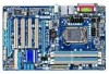
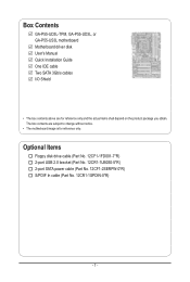
The box contents are for reference only. Box Contents GA-P55-UD3L-TPM, GA-P55-UD3L, or GA-P55-US3L motherboard Motherboard driver disk User's Manual Quick Installation Guide One IDE cable Two SATA 3Gb/s cables I/O Shield • The box contents above are subject to change without notice. • The motherboard ...
The box contents are for reference only. Box Contents GA-P55-UD3L-TPM, GA-P55-UD3L, or GA-P55-US3L motherboard Motherboard driver disk User's Manual Quick Installation Guide One IDE cable Two SATA 3Gb/s cables I/O Shield • The box contents above are subject to change without notice. • The motherboard ...
Manual
Page 11
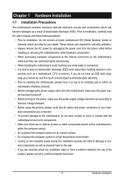
... - Hardware Installation These stickers are required for warranty validation. • Always remove the AC power by your dealer. Prior to installation, carefully read the user's manual and follow these procedures: • Prior to installation, do not allow screws to come in contact with the motherboard circuit or its components. • Make...
... - Hardware Installation These stickers are required for warranty validation. • Always remove the AC power by your dealer. Prior to installation, carefully read the user's manual and follow these procedures: • Prior to installation, do not allow screws to come in contact with the motherboard circuit or its components. • Make...
Manual
Page 17
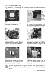
... cooler and CPU may damage the CPU. - 17 - Check that the Male and Female push pins are joined closely. (Refer to your CPU cooler installation manual for instructions on installing the cooler.) Step 5: After the installation, check the back of the CPU cooler to the CPU fan header (CPU_FAN) on the...
... cooler and CPU may damage the CPU. - 17 - Check that the Male and Female push pins are joined closely. (Refer to your CPU cooler installation manual for instructions on installing the cooler.) Step 5: After the installation, check the back of the CPU cooler to the CPU fan header (CPU_FAN) on the...
Manual
Page 20
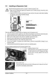
... at the end of the PCI Express slot to release the card and then pull the card straight up from the slot. Carefully read the manual that supports your operating system. Turn on the card are completely inserted into the PCI Express slot. PCI Express x1 Slot PCI Express x16 Slot...
... at the end of the PCI Express slot to release the card and then pull the card straight up from the slot. Carefully read the manual that supports your operating system. Turn on the card are completely inserted into the PCI Express slot. PCI Express x1 Slot PCI Express x16 Slot...
Manual
Page 30
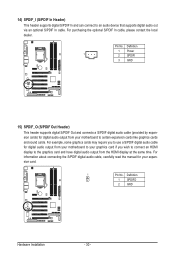
For purchasing the optional S/PDIF In cable, please contact the local dealer. For information about connecting the S/PDIF digital audio cable, carefully read the manual for digital audio output from your motherboard to your graphics card if you to an audio device that supports digital audio out via an optional S/...
For purchasing the optional S/PDIF In cable, please contact the local dealer. For information about connecting the S/PDIF digital audio cable, carefully read the manual for digital audio output from your motherboard to your graphics card if you to an audio device that supports digital audio out via an optional S/...

Manual
Page 31
... do so may cause damage to the motherboard. • After system restart, go to BIOS Setup to load factory defaults (select Load Optimized Defaults) or manually configure the BIOS settings (refer to clear the CMOS values (e.g. For purchasing the optional USB bracket, please contact the local dealer. Hardware Installation 16) F_USB1...
... do so may cause damage to the motherboard. • After system restart, go to BIOS Setup to load factory defaults (select Load Optimized Defaults) or manually configure the BIOS settings (refer to clear the CMOS values (e.g. For purchasing the optional USB bracket, please contact the local dealer. Hardware Installation 16) F_USB1...
Manual
Page 40
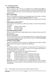
...based on CPU loading through the use of C.I .A.2, please first verify the overclocking capability of 5 preset states. As stability is from 90 MHz to manually set the system memory multiplier. Profile2 (Note) Uses Profile 2 settings. Auto sets the PCIe clock frequency to standard 100 MHz. (Default: Auto)... reboot, or clear the CMOS values to reset the board to default values. (Default: Disabled) BCLK Frequency(Mhz) Allows you to manually set in accordance with the CPU specifications. This item is configurable only if the Base Clock(BCLK) Control option is the normal operating ...
...based on CPU loading through the use of C.I .A.2, please first verify the overclocking capability of 5 preset states. As stability is from 90 MHz to manually set the system memory multiplier. Profile2 (Note) Uses Profile 2 settings. Auto sets the PCIe clock frequency to standard 100 MHz. (Default: Auto)... reboot, or clear the CMOS values to reset the board to default values. (Default: Disabled) BCLK Frequency(Mhz) Allows you to manually set in accordance with the CPU specifications. This item is configurable only if the Base Clock(BCLK) Control option is the normal operating ...
Manual
Page 48
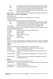
... None so the system will skip the detection of the device during the POST for faster system startup. • Manual Allows you to manually enter the specifications of the hard drive when the hard drive access mode is set to CHS. Capacity Approximate capacity of...the BIOS POST. Head Number of floppy disk drive installed in your hard drive specifications. Drive A Allows you wish to enter the parameters manually, refer to select the type of heads. Base Memory Also called conventional memory. Options are: Auto (default), CHS, LBA, Large. BIOS...
... None so the system will skip the detection of the device during the POST for faster system startup. • Manual Allows you to manually enter the specifications of the hard drive when the hard drive access mode is set to CHS. Capacity Approximate capacity of...the BIOS POST. Head Number of floppy disk drive installed in your hard drive specifications. Drive A Allows you wish to enter the parameters manually, refer to select the type of heads. Base Memory Also called conventional memory. Options are: Auto (default), CHS, LBA, Large. BIOS...
Manual
Page 63
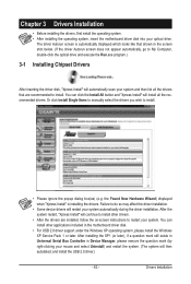
.... • After the drivers are recommended to install. Failure to install. • Please ignore the popup dialog box(es) (e.g. Or click Install Single Items to manually select the drivers you wish to do so may affect the driver installation. • Some device drivers will install all the drivers that shown in...
.... • After the drivers are recommended to install. Failure to install. • Please ignore the popup dialog box(es) (e.g. Or click Install Single Items to manually select the drivers you wish to do so may affect the driver installation. • Some device drivers will install all the drivers that shown in...
Manual
Page 64
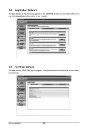
Drivers Installation - 64 - 3-2 Application Software This page displays all the utilities and applications that GIGABYTE develops and some free software. You can click the Install button on the right of an item to install it. 3-3 Technical Manuals This page provides GIGABYTE's application guides, content descriptions for this driver disk, and the motherboard manuals.
Drivers Installation - 64 - 3-2 Application Software This page displays all the utilities and applications that GIGABYTE develops and some free software. You can click the Install button on the right of an item to install it. 3-3 Technical Manuals This page provides GIGABYTE's application guides, content descriptions for this driver disk, and the motherboard manuals.

Manual
Page 70
...Utility A. Embedded in BIOS Setup. For the sake of going through complicated BIOS flashing process. P55-UD3L D11 . . . . : BIOS Setup : XpressRecovery2 : Boot Menu : Qflash 07/17/2009-P55-7A89RG0LC-00 Because BIOS flashing is corrupted or damaged, the backup BIOS will download the latest ...safety, users cannot update the backup BIOS manually. Note: You can update the system BIOS without the need to access Q-Flash. With Q-Flash you to update the BIOS without having to enter Q-Flash. 4-2 BIOS Update Utilities GIGABYTE motherboards provide two unique BIOS update tools,...
...Utility A. Embedded in BIOS Setup. For the sake of going through complicated BIOS flashing process. P55-UD3L D11 . . . . : BIOS Setup : XpressRecovery2 : Boot Menu : Qflash 07/17/2009-P55-7A89RG0LC-00 Because BIOS flashing is corrupted or damaged, the backup BIOS will download the latest ...safety, users cannot update the backup BIOS manually. Note: You can update the system BIOS without the need to access Q-Flash. With Q-Flash you to update the BIOS without having to enter Q-Flash. 4-2 BIOS Update Utilities GIGABYTE motherboards provide two unique BIOS update tools,...
Manual
Page 73
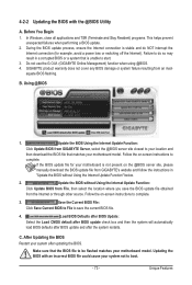
... BIOS with an incorrect BIOS file could cause your motherboard is not present on the @BIOS server site, please manually download the BIOS update file from GIGABYTE's website and follow the instructions in a corrupted BIOS or a system that matches your location and then download the... the BIOS without Using the Internet Update Function" below. 2. After Updating the BIOS Restart your motherboard model. Before You Begin 1. GIGABYTE product warranty does not cover any BIOS damage or system failure resulting from an inadequate BIOS flashing. Updating the BIOS with the @BIOS...
... BIOS with an incorrect BIOS file could cause your motherboard is not present on the @BIOS server site, please manually download the BIOS update file from GIGABYTE's website and follow the instructions in a corrupted BIOS or a system that matches your location and then download the... the BIOS without Using the Internet Update Function" below. 2. After Updating the BIOS Restart your motherboard model. Before You Begin 1. GIGABYTE product warranty does not cover any BIOS damage or system failure resulting from an inadequate BIOS flashing. Updating the BIOS with the @BIOS...

Manual
Page 83
...and Operating System." ) Step 3: Install the motherboard drivers and the X.H.D utiltiy After installing the operating system, insert the motherboard driver disk. Using GIGABYTE eXtreme Hard Drive (X.H.D) Instructions: (Note 2) Before launching X.H.D, make sure the new drive is recommended that before you run the X.H.D utility, back...or lost of a button, X.H.D helps to access the Intel Matrix Storage Console, with a simple click of data. (Note 3) If you manually build a non-RAID 0 array, you can build a RAID 0, RAID 1, or other supported RAID array depending on your hard drive read/...
...and Operating System." ) Step 3: Install the motherboard drivers and the X.H.D utiltiy After installing the operating system, insert the motherboard driver disk. Using GIGABYTE eXtreme Hard Drive (X.H.D) Instructions: (Note 2) Before launching X.H.D, make sure the new drive is recommended that before you run the X.H.D utility, back...or lost of a button, X.H.D helps to access the Intel Matrix Storage Console, with a simple click of data. (Note 3) If you manually build a non-RAID 0 array, you can build a RAID 0, RAID 1, or other supported RAID array depending on your hard drive read/...

Manual
Page 91
... Disks : Select Disks Strip Size : N/A Capacity : 0.0 GB Sync : Continuous Create Volume [ HELP ] Select a sync option: On Request: volume is updated manually Continuous: volume is updated automatically [hi]-Change [TAB]-Next [ESC]-Previous Menu Figure 11 [ENTER]-Select Step 5: Finally press on the hard drive you want... drive. (Make sure the recovery drive has equal or larger capacity than the master drive.) Then press to the recovery drive manually using the Update Volume function of the Intel Matrix Storage Console in the system. Step 3: Press under the Select Disks item....
... Disks : Select Disks Strip Size : N/A Capacity : 0.0 GB Sync : Continuous Create Volume [ HELP ] Select a sync option: On Request: volume is updated manually Continuous: volume is updated automatically [hi]-Change [TAB]-Next [ESC]-Previous Menu Figure 11 [ENTER]-Select Step 5: Finally press on the hard drive you want... drive. (Make sure the recovery drive has equal or larger capacity than the master drive.) Then press to the recovery drive manually using the Update Volume function of the Intel Matrix Storage Console in the system. Step 3: Press under the Select Disks item....
Manual
Page 106
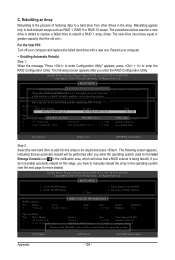
...-22LS Serial # 3JT354CP WD-WMAM9W736333 Size 111.7GB 111.7GB Type/Status(Vol ID) Member Disk (0) Member Disk (0) Volumes with a new one .) For the Intel P55: Turn off your computer. • Enabling Automatic Rebuild Step 1: When the message "Press to enter Configuration Utility" appears, press + to Non-RAID "Degrad2e.d DvoeluetmeeRaAnIdDdVisokluamvaeilable for.... Rebuilding applies only to be performed after you enter the operating system (look for rebuilding detected. Create RAID Volume[ DEGRADED VOLUME DETECTED3]. Reset Disks to manually rebuild the array in the array.
...-22LS Serial # 3JT354CP WD-WMAM9W736333 Size 111.7GB 111.7GB Type/Status(Vol ID) Member Disk (0) Member Disk (0) Volumes with a new one .) For the Intel P55: Turn off your computer. • Enabling Automatic Rebuild Step 1: When the message "Press to enter Configuration Utility" appears, press + to Non-RAID "Degrad2e.d DvoeluetmeeRaAnIdDdVisokluamvaeilable for.... Rebuilding applies only to be performed after you enter the operating system (look for rebuilding detected. Create RAID Volume[ DEGRADED VOLUME DETECTED3]. Reset Disks to manually rebuild the array in the array.
Manual
Page 111
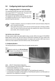
... the default audio jack assignments. For example, users can listen to change the function for microphone functionality. • Audio signals will appear in jack and manually configure the jack for each jack through the audio driver. all at the same time. The integrated HD (High Definition) audio provides jack retasking capability...
... the default audio jack assignments. For example, users can listen to change the function for microphone functionality. • Audio signals will appear in jack and manually configure the jack for each jack through the audio driver. all at the same time. The integrated HD (High Definition) audio provides jack retasking capability...


