Manual
Page 1
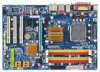
GA-P35-DS3L/ GA-P35-S3L LGA775 socket motherboard for Intel® CoreTM processor family/ Intel® Pentium® processor family/Intel® Celeron® processor family User's Manual Rev. 2001 12ME-P35DS3L-2001R * The WEEE marking on the product indicates this product must not be disposed of with user's other household waste and must be handed over to a designated collection point for the recycling of waste electrical and electronic equipment!! * The WEEE marking applies only in European Union's member states.
GA-P35-DS3L/ GA-P35-S3L LGA775 socket motherboard for Intel® CoreTM processor family/ Intel® Pentium® processor family/Intel® Celeron® processor family User's Manual Rev. 2001 12ME-P35DS3L-2001R * The WEEE marking on the product indicates this product must not be disposed of with user's other household waste and must be handed over to a designated collection point for the recycling of waste electrical and electronic equipment!! * The WEEE marking applies only in European Union's member states.

Manual
Page 2
Motherboard GA-P35-DS3L/GA-P35-S3L Jul. 31, 2007 Motherboard GA-P35-DS3L/GA-P35-S3L Jul. 31, 2007
Motherboard GA-P35-DS3L/GA-P35-S3L Jul. 31, 2007 Motherboard GA-P35-DS3L/GA-P35-S3L Jul. 31, 2007
Manual
Page 4
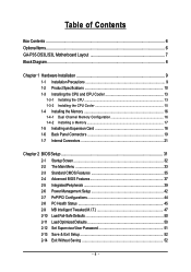
Table of Contents Box Contents ...6 OptionalItems ...6 GA-P35-DS3L/S3L Motherboard Layout 7 Block Diagram ...8 Chapter 1 Hardware Installation 9 1-1 Installation Precautions 9 1-2 Product Specifications 10 1-3 Installing the CPU and CPU Cooler 13 1-3-1 Installing the CPU 13 1-3-2 Installing ...
Table of Contents Box Contents ...6 OptionalItems ...6 GA-P35-DS3L/S3L Motherboard Layout 7 Block Diagram ...8 Chapter 1 Hardware Installation 9 1-1 Installation Precautions 9 1-2 Product Specifications 10 1-3 Installing the CPU and CPU Cooler 13 1-3-1 Installing the CPU 13 1-3-2 Installing ...
Manual
Page 6
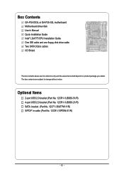
... USB 2.0 bracket (Part No. 12CR1-1UB030-21/R) SATA bracket (Part No. 12CF1-3SATPW-11R) S/PDIF in cable (Part No. 12CR1-1SPDIN-01/R) - 6 - Box Contents GA-P35-DS3L or GA-P35-S3L motherboard Motherboard driver disk User's Manual Quick Installation Guide Intel® LGA775 CPU Installation Guide One IDE cable and one floppy disk drive cable...
... USB 2.0 bracket (Part No. 12CR1-1UB030-21/R) SATA bracket (Part No. 12CF1-3SATPW-11R) S/PDIF in cable (Part No. 12CR1-1SPDIN-01/R) - 6 - Box Contents GA-P35-DS3L or GA-P35-S3L motherboard Motherboard driver disk User's Manual Quick Installation Guide Intel® LGA775 CPU Installation Guide One IDE cable and one floppy disk drive cable...

Manual
Page 7
GA-P35-DS3L/S3L Motherboard Layout KB_MS COAXIAL OPTICAL ATX_12V LGA775 CPU_FAN ATX COM LPT DDRII1 GA-P35-DS3L/S3L R_USB SYS_FAN2 USB LAN F_AUDIO AUDIO SYS_FAN1 PCIE_3 RTL8111B PCIE_16 PCIE_1 SPDIF_O CODEC PCIE_2 SPDIF_I PCI1 PCI2 IT8718 PCI3 CD_IN Intel® P35 FDD DDRII3 DDRII4 DDRII2 PWR_FAN Intel® ICH9 BATTERY CLR_CMOS SATAII0 SATAII1 JMicron 368 SATAII4 BIOS SATAII5 IDE1 F_USB3 F_USB2 F_USB1 CI F_PANEL PWR_LED "*" Only the GA-P35-DS3L adopts All-Solid Capacitor design. - 7 -
GA-P35-DS3L/S3L Motherboard Layout KB_MS COAXIAL OPTICAL ATX_12V LGA775 CPU_FAN ATX COM LPT DDRII1 GA-P35-DS3L/S3L R_USB SYS_FAN2 USB LAN F_AUDIO AUDIO SYS_FAN1 PCIE_3 RTL8111B PCIE_16 PCIE_1 SPDIF_O CODEC PCIE_2 SPDIF_I PCI1 PCI2 IT8718 PCI3 CD_IN Intel® P35 FDD DDRII3 DDRII4 DDRII2 PWR_FAN Intel® ICH9 BATTERY CLR_CMOS SATAII0 SATAII1 JMicron 368 SATAII4 BIOS SATAII5 IDE1 F_USB3 F_USB2 F_USB1 CI F_PANEL PWR_LED "*" Only the GA-P35-DS3L adopts All-Solid Capacitor design. - 7 -
Manual
Page 8
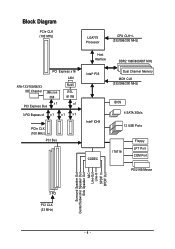
Block Diagram PCIe CLK (100 MHz) LGA775 Processor CPU CLK+/(333/266/200 MHz) PCI Express x16 LAN ATA-133/100/66/33 IDE Channel JMicron 368 x1 PCI Express Bus RJ45 RTL 8111B x1 3 PCI Express x1 x 1 x1 x1 PCIe CLK (100 MHz) PCI Bus Host Interface DDR2 1066/800/667 MHz Intel® P35 Dual Channel Memory MCH CLK (333/266/200 MHz) Intel® ICH9 BIOS 4 SATA 3Gb/s 12 USB Ports CODEC IT8718 Floppy LPT Port COM Port PS/2 KB/Mouse Surround Speaker Out Center/Subwoofer Speaker Out Side Speaker Out MIC Line-Out Line-In SPDIF In SPDIF Out 3 PCI PCI CLK (33 MHz) - 8 -
Block Diagram PCIe CLK (100 MHz) LGA775 Processor CPU CLK+/(333/266/200 MHz) PCI Express x16 LAN ATA-133/100/66/33 IDE Channel JMicron 368 x1 PCI Express Bus RJ45 RTL 8111B x1 3 PCI Express x1 x 1 x1 x1 PCIe CLK (100 MHz) PCI Bus Host Interface DDR2 1066/800/667 MHz Intel® P35 Dual Channel Memory MCH CLK (333/266/200 MHz) Intel® ICH9 BIOS 4 SATA 3Gb/s 12 USB Ports CODEC IT8718 Floppy LPT Port COM Port PS/2 KB/Mouse Surround Speaker Out Center/Subwoofer Speaker Out Side Speaker Out MIC Line-Out Line-In SPDIF In SPDIF Out 3 PCI PCI CLK (33 MHz) - 8 -
Manual
Page 10
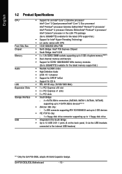
.../Intel® Pentium® 4 processor/ Intel® Celeron® processor in the LGA 775 package (Go to GIGABYTE's website for the latest CPU support list.) Š Support for Intel® Hyper-Threading Technology Š L2 cache...Note 1) Š Dual channel memory architecture Š Support for DDR2 1066/800/667 MHz memory modules (Go to GIGABYTE's website for the latest memory support list.) Š Realtek ALC888 codec Š High Definition Audio Š 2/4/5.1/7.1-channel... USB brackets connected to the internal USB headers) "*" Only the GA-P35-DS3L adopts All-Solid Capacitor design.
.../Intel® Pentium® 4 processor/ Intel® Celeron® processor in the LGA 775 package (Go to GIGABYTE's website for the latest CPU support list.) Š Support for Intel® Hyper-Threading Technology Š L2 cache...Note 1) Š Dual channel memory architecture Š Support for DDR2 1066/800/667 MHz memory modules (Go to GIGABYTE's website for the latest memory support list.) Š Realtek ALC888 codec Š High Definition Audio Š 2/4/5.1/7.1-channel... USB brackets connected to the internal USB headers) "*" Only the GA-P35-DS3L adopts All-Solid Capacitor design.
Manual
Page 12
... for AHCI mode. (Refer to Chapter 2, "BIOS Setup," "Integrated Peripherals," for details on enabling AHCI.) (Note 3) Available functions in Easytune may differ by motherboard model. GA-P35-DS3L/S3L Motherboard - 12 -
... for AHCI mode. (Refer to Chapter 2, "BIOS Setup," "Integrated Peripherals," for details on enabling AHCI.) (Note 3) Available functions in Easytune may differ by motherboard model. GA-P35-DS3L/S3L Motherboard - 12 -

Manual
Page 14
... the CPU into the motherboard CPU socket. Step 4: Hold the CPU with the socket alignment keys) and gently insert the CPU into its locked position. GA-P35-DS3L/S3L Motherboard - 14 - CPU Socket Lever Step 1: Completely raise the CPU socket lever. Align the CPU pin one marking (triangle) with the pin one corner...
... the CPU into the motherboard CPU socket. Step 4: Hold the CPU with the socket alignment keys) and gently insert the CPU into its locked position. GA-P35-DS3L/S3L Motherboard - 14 - CPU Socket Lever Step 1: Completely raise the CPU socket lever. Align the CPU pin one marking (triangle) with the pin one corner...
Manual
Page 16
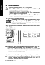
...the memory is operating in only one DDR2 memory module is installed. 2. Dual Channel mode cannot be used and installed in Dual Channel mode. 1. GA-P35-DS3L/S3L Motherboard - 16 - DS/SS - - When memory modules of the same capacity, brand, speed, and chips be enabled if only one ...direction. Intel® Flex Memory Technology offers greater flexibility to upgrade by allowing different memory sizes to GIGABYTE's website for the latest memory support list.) • Always turn off the computer and unplug the power cord from the power outlet...
...the memory is operating in only one DDR2 memory module is installed. 2. Dual Channel mode cannot be used and installed in Dual Channel mode. 1. GA-P35-DS3L/S3L Motherboard - 16 - DS/SS - - When memory modules of the same capacity, brand, speed, and chips be enabled if only one ...direction. Intel® Flex Memory Technology offers greater flexibility to upgrade by allowing different memory sizes to GIGABYTE's website for the latest memory support list.) • Always turn off the computer and unplug the power cord from the power outlet...
Manual
Page 18
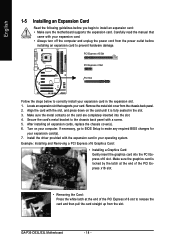
... from the chassis back panel. 2. If necessary, go to BIOS Setup to make any required BIOS changes for your expansion card in the expansion slot. 1. GA-P35-DS3L/S3L Motherboard - 18 - Make sure the metal contacts on your expansion card. • Always turn off the computer and unplug the power cord from the...
... from the chassis back panel. 2. If necessary, go to BIOS Setup to make any required BIOS changes for your expansion card in the expansion slot. 1. GA-P35-DS3L/S3L Motherboard - 18 - Make sure the metal contacts on your expansion card. • Always turn off the computer and unplug the power cord from the...
Manual
Page 20
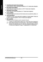
... audio jack to the instructions on setting up a 2/4/5.1/ 7.1-channel audio configuration in Chapter 5, "Configuring 2/4/5.1/7.1-Channel Audio." Refer to connect side speakers in a 4/5.1/7.1-channel audio configuration. GA-P35-DS3L/S3L Motherboard - 20 - English Center/Subwoofer Speaker Out Jack (Orange) Use this audio jack to perform different functions via the audio software. Use this audio...
... audio jack to the instructions on setting up a 2/4/5.1/ 7.1-channel audio configuration in Chapter 5, "Configuring 2/4/5.1/7.1-Channel Audio." Refer to connect side speakers in a 4/5.1/7.1-channel audio configuration. GA-P35-DS3L/S3L Motherboard - 20 - English Center/Subwoofer Speaker Out Jack (Orange) Use this audio jack to perform different functions via the audio software. Use this audio...

Manual
Page 22
... Definition 3.3V -12V GND PS_ON(soft On/Off) GND GND GND -5V +5V +5V +5V (Only for 2x12-pinATX) GND (Only for 2x12-pin ATX) GA-P35-DS3L/S3L Motherboard - 22 -
... Definition 3.3V -12V GND PS_ON(soft On/Off) GND GND GND -5V +5V +5V +5V (Only for 2x12-pinATX) GND (Only for 2x12-pin ATX) GA-P35-DS3L/S3L Motherboard - 22 -
Manual
Page 24
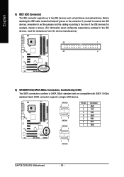
... drives and optical drives. Each SATA connector supports a single SATA device. SATAII0 7 1 1 7 SATAII1 SATAII4 7 1 Pin No. 1 2 3 4 5 6 7 Definition GND TXP TXN GND RXN RXP GND 1 7 SATAII5 GA-P35-DS3L/S3L Motherboard - 24 - Before attaching the IDE cable, locate the foolproof groove on the connector.
... drives and optical drives. Each SATA connector supports a single SATA device. SATAII0 7 1 1 7 SATAII1 SATAII4 7 1 Pin No. 1 2 3 4 5 6 7 Definition GND TXP TXN GND RXN RXP GND 1 7 SATAII5 GA-P35-DS3L/S3L Motherboard - 24 - Before attaching the IDE cable, locate the foolproof groove on the connector.
Manual
Page 26
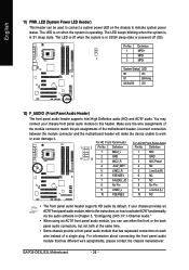
...." • When using an AC'97 front panel audio module, you can be used to connect a system power LED on the chassis to this header. GA-P35-DS3L/S3L Motherboard - 26 - The LED keeps blinking when the system is in S1 sleep state. If your chassis front panel audio module to indicate system...
...." • When using an AC'97 front panel audio module, you can be used to connect a system power LED on the chassis to this header. GA-P35-DS3L/S3L Motherboard - 26 - The LED keeps blinking when the system is in S1 sleep state. If your chassis front panel audio module to indicate system...

Manual
Page 28
... IEEE 1394 bracket (2x5-pin) cable into the USB header. • Prior to installing the USB bracket, be sure to turn off your expansion card. GA-P35-DS3L/S3L Motherboard - 28 - Pin No.
... IEEE 1394 bracket (2x5-pin) cable into the USB header. • Prior to installing the USB bracket, be sure to turn off your expansion card. GA-P35-DS3L/S3L Motherboard - 28 - Pin No.
Manual
Page 30
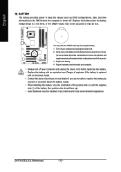
... the battery: 1. English 19) BATTERY The battery provides power to touch the positive and negative terminals of the battery holder, making them short for one . GA-P35-DS3L/S3L Motherboard - 30 - You may be handled in the CMOS when the computer is replaced with local environmental regulations.
... the battery: 1. English 19) BATTERY The battery provides power to touch the positive and negative terminals of the battery holder, making them short for one . GA-P35-DS3L/S3L Motherboard - 30 - You may be handled in the CMOS when the computer is replaced with local environmental regulations.
Manual
Page 32
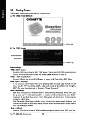
...to access the Q-Flash utility directly without having to set the first boot device without entering BIOS Setup. Note: The setting in Boot Menu. GA-P35-DS3L/S3L Motherboard - 32 - The system will still be used for subsequent access to accept. You can be based on page 38. : BIOS... restart, the device boot order will directly boot from the device configured in Boot Menu is effective for P35-DS3L F3a . . . . : BIOS Setup/Q-Flash : XpressRecovery2 : Boot Menu : Qflash 07/12/2007-P35-ICH9-6A79OG0TC-00 Function Keys Function Keys: : POST Screen Press the key to show the BIOS POST...
...to access the Q-Flash utility directly without having to set the first boot device without entering BIOS Setup. Note: The setting in Boot Menu. GA-P35-DS3L/S3L Motherboard - 32 - The system will still be used for subsequent access to accept. You can be based on page 38. : BIOS... restart, the device boot order will directly boot from the device configured in Boot Menu is effective for P35-DS3L F3a . . . . : BIOS Setup/Q-Flash : XpressRecovery2 : Boot Menu : Qflash 07/12/2007-P35-ICH9-6A79OG0TC-00 Function Keys Function Keys: : POST Screen Press the key to show the BIOS POST...
Manual
Page 33
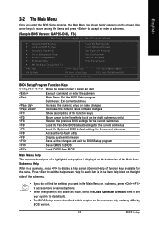
... function keys available for the menu. Use arrow keys to move among the items and press to accept or enter a sub-menu. (Sample BIOS Version: GA-P35-DS3L F3a) CMOS Setup Utility-Copyright (C) 1984-2007 Award Software ` Standard CMOS Features ` Advanced BIOS Features ` Integrated Peripherals ` Power Management Setup ` PnP/PCI Configurations ` PC Health...
... function keys available for the menu. Use arrow keys to move among the items and press to accept or enter a sub-menu. (Sample BIOS Version: GA-P35-DS3L F3a) CMOS Setup Utility-Copyright (C) 1984-2007 Award Software ` Standard CMOS Features ` Advanced BIOS Features ` Integrated Peripherals ` Power Management Setup ` PnP/PCI Configurations ` PC Health...
Manual
Page 34
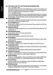
... allows you to restrict access to the system and BIOS Setup. First enter the profile name (to erase the default profile name, use this task.) GA-P35-DS3L/S3L Motherboard - 34 - It allows you to restrict access to the system and BIOS Setup. A supervisor password allows you wish to load, then press to...
... allows you to restrict access to the system and BIOS Setup. First enter the profile name (to erase the default profile name, use this task.) GA-P35-DS3L/S3L Motherboard - 34 - It allows you to restrict access to the system and BIOS Setup. A supervisor password allows you wish to load, then press to...
