Manual
Page 4
... ...6 GA-P35-DS3L/S3L Motherboard Layout 7 Block Diagram ...8 Chapter 1 Hardware Installation 9 1-1 Installation Precautions 9 1-2 Product Specifications 10 1-3 Installing the CPU and CPU Cooler 13 1-3-1 Installing the CPU 13 1-3-2 Installing the CPU Cooler 15 1-4 Installing the Memory 16 1-4-1 Dual Channel Memory Configuration 16 1-4-2 Installing a Memory 17 1-5 Installing an Expansion Card 18 1-6 Back Panel Connectors 19 1-7 Internal Connectors 21 Chapter 2 BIOS Setup 31 2-1 Startup Screen 32 2-2 The Main Menu 33 2-3 Standard CMOS Features 35 2-4 Advanced BIOS Features...
... ...6 GA-P35-DS3L/S3L Motherboard Layout 7 Block Diagram ...8 Chapter 1 Hardware Installation 9 1-1 Installation Precautions 9 1-2 Product Specifications 10 1-3 Installing the CPU and CPU Cooler 13 1-3-1 Installing the CPU 13 1-3-2 Installing the CPU Cooler 15 1-4 Installing the Memory 16 1-4-1 Dual Channel Memory Configuration 16 1-4-2 Installing a Memory 17 1-5 Installing an Expansion Card 18 1-6 Back Panel Connectors 19 1-7 Internal Connectors 21 Chapter 2 BIOS Setup 31 2-1 Startup Screen 32 2-2 The Main Menu 33 2-3 Standard CMOS Features 35 2-4 Advanced BIOS Features...
Manual
Page 12
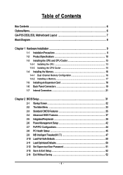
... actual memory size displayed will be less than 4 GB. (Note 2) To enable hot plug capability for the SATA connectors (SATAII0, SATAII1, SATAII4, SATAII5) controlled by the ICH9 South Bridge, you must install Windows Vista (on ICH9, hot plug is supported in Windows Vista only) and configure the SATA connectors for AHCI mode. (Refer to Chapter 2, "BIOS Setup," "Integrated Peripherals," for details on enabling AHCI.) (Note 3) Available functions in Easytune may differ by motherboard model.
... actual memory size displayed will be less than 4 GB. (Note 2) To enable hot plug capability for the SATA connectors (SATAII0, SATAII1, SATAII4, SATAII5) controlled by the ICH9 South Bridge, you must install Windows Vista (on ICH9, hot plug is supported in Windows Vista only) and configure the SATA connectors for AHCI mode. (Refer to Chapter 2, "BIOS Setup," "Integrated Peripherals," for details on enabling AHCI.) (Note 3) Available functions in Easytune may differ by motherboard model.
Manual
Page 16
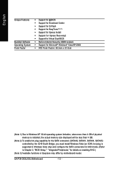
... DDRII3 DDRII4 Due to insert the memory, switch the direction. 1-4-1 Dual Channel Memory Configuration This motherboard provides four DDR2 memory sockets and supports Dual Channel Technology. GA-P35-DS3L/S3L Motherboard - 16 - After the memory is installed, the BIOS will automatically detect the specifications and capacity of different capacity and chips are installed, a message which says memory is recommended that the motherboard supports the memory. DS/SS - - When memory modules of the memory. Four Modules DS/SS DS/SS...
... DDRII3 DDRII4 Due to insert the memory, switch the direction. 1-4-1 Dual Channel Memory Configuration This motherboard provides four DDR2 memory sockets and supports Dual Channel Technology. GA-P35-DS3L/S3L Motherboard - 16 - After the memory is installed, the BIOS will automatically detect the specifications and capacity of different capacity and chips are installed, a message which says memory is recommended that the motherboard supports the memory. DS/SS - - When memory modules of the memory. Four Modules DS/SS DS/SS...
Manual
Page 18
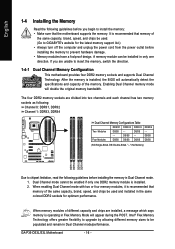
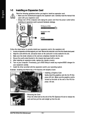
... PCI Express x16 slot. GA-P35-DS3L/S3L Motherboard - 18 - Remove the metal slot cover from the slot. Secure the card's metal bracket to release the card and then pull the card straight up from the chassis back panel. 2. Carefully read the manual that supports your operating system. PCI Express x16 Slot PCI Express x1 Slot PCI Slot Follow the steps below to correctly install your expansion card(s). 7. After installing all expansion cards, replace the chassis cover(s). 6. Example: Installing and Removing a PCI Express x16 Graphics Card: • Installing a Graphics...
... PCI Express x16 slot. GA-P35-DS3L/S3L Motherboard - 18 - Remove the metal slot cover from the slot. Secure the card's metal bracket to release the card and then pull the card straight up from the chassis back panel. 2. Carefully read the manual that supports your operating system. PCI Express x16 Slot PCI Express x1 Slot PCI Slot Follow the steps below to correctly install your expansion card(s). 7. After installing all expansion cards, replace the chassis cover(s). 6. Example: Installing and Removing a PCI Express x16 Graphics Card: • Installing a Graphics...
Manual
Page 23
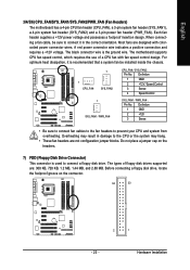
... header supplies a +12V power voltage and possesses a foolproof insertion design. When connecting a fan cable, be sure to connect a floppy disk drive. The black connector wire is used to connect it is recommended that a system fan be installed inside the chassis. 1 1 CPU_FAN SYS_FAN2 CPU_FAN / SYS_FAN2: Pin No. Definition 1 GND 2 +12V / Speed Control 3 Sense 4 Speed Control 1 SYS_FAN1 / PWR_FAN SYS_FAN1 / PWR_FAN : Pin No. Overheating may hang. • These fan headers are not configuration jumper blocks. The types of a CPU fan with colorcoded power connector wires...
... header supplies a +12V power voltage and possesses a foolproof insertion design. When connecting a fan cable, be sure to connect a floppy disk drive. The black connector wire is used to connect it is recommended that a system fan be installed inside the chassis. 1 1 CPU_FAN SYS_FAN2 CPU_FAN / SYS_FAN2: Pin No. Definition 1 GND 2 +12V / Speed Control 3 Sense 4 Speed Control 1 SYS_FAN1 / PWR_FAN SYS_FAN1 / PWR_FAN : Pin No. Overheating may hang. • These fan headers are not configuration jumper blocks. The types of a CPU fan with colorcoded power connector wires...
Manual
Page 26
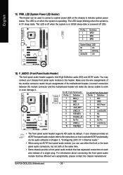
... when the system is in S3/S4 sleep state or powered off when the system is in Chapter 5, "Configuring 2/4/5.1/7.1-Channel Audio." • When using an AC'97 front panel audio module, you can be used to connect a system power LED on each wire instead of the motherboard header. For HD Front Panel Audio: For AC'97 Front Panel Audio: 1 2 Pin No. GA-P35-DS3L/S3L Motherboard - 26 - The LED is off (S5). Definition 1 MIC2_L 1 MIC...
... when the system is in S3/S4 sleep state or powered off when the system is in Chapter 5, "Configuring 2/4/5.1/7.1-Channel Audio." • When using an AC'97 front panel audio module, you can be used to connect a system power LED on each wire instead of the motherboard header. For HD Front Panel Audio: For AC'97 Front Panel Audio: 1 2 Pin No. GA-P35-DS3L/S3L Motherboard - 26 - The LED is off (S5). Definition 1 MIC2_L 1 MIC...

Manual
Page 28
... HDMI display at the same time. Definition 1 Power (5V) 9 1 10 2 2 Power (5V) 3 USB DX- 4 USB DY- 5 USB DX+ 6 USB DY+ 7 GND 8 GND 9 No Pin 10 NC • Do not plug the IEEE 1394 bracket (2x5-pin) cable into the USB header. • Prior to installing the USB bracket, be sure to USB 2.0/1.1 specification. GA-P35-DS3L/S3L Motherboard - 28 - Each USB header can provide two USB ports via an optional USB bracket. English 15) SPDIF_O (S/PDIF Out Header) This header supports...
... HDMI display at the same time. Definition 1 Power (5V) 9 1 10 2 2 Power (5V) 3 USB DX- 4 USB DY- 5 USB DX+ 6 USB DY+ 7 GND 8 GND 9 No Pin 10 NC • Do not plug the IEEE 1394 bracket (2x5-pin) cable into the USB header. • Prior to installing the USB bracket, be sure to USB 2.0/1.1 specification. GA-P35-DS3L/S3L Motherboard - 28 - Each USB header can provide two USB ports via an optional USB bracket. English 15) SPDIF_O (S/PDIF Out Header) This header supports...

Manual
Page 29
... seconds. Failure to do so may cause damage to the motherboard. • After system restart, go to BIOS Setup to load factory defaults (select Load Optimized Defaults) or manually configure the BIOS settings (refer to touch the two pins for BIOS configurations). - 29 - Hardware Installation This function requires a chassis with chassis intrusion detection design. Open: Normal Short: Clear CMOS Values • Always turn off your computer and unplug the power cord from the jumper.
... seconds. Failure to do so may cause damage to the motherboard. • After system restart, go to BIOS Setup to load factory defaults (select Load Optimized Defaults) or manually configure the BIOS settings (refer to touch the two pins for BIOS configurations). - 29 - Hardware Installation This function requires a chassis with chassis intrusion detection design. Open: Normal Short: Clear CMOS Values • Always turn off your computer and unplug the power cord from the jumper.
Manual
Page 32
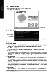
GA-P35-DS3L/S3L Motherboard - 32 - Motherboard Model BIOS Version Intel P35 BIOS for one time only. To show the BIOS POST screen. You can be based on page 38. : BIOS Setup/Q-Flash Press the key to enter BIOS Setup or to access the Q-Flash utility in BIOS Setup. : Xpress Recovery2 If you to set the first boot device without having to access the Q-Flash utility directly without entering BIOS Setup. To exit Boot Menu, press . After system restart, the device boot order will directly boot from the device configured in Boot Menu is...
GA-P35-DS3L/S3L Motherboard - 32 - Motherboard Model BIOS Version Intel P35 BIOS for one time only. To show the BIOS POST screen. You can be based on page 38. : BIOS Setup/Q-Flash Press the key to enter BIOS Setup or to access the Q-Flash utility in BIOS Setup. : Xpress Recovery2 If you to set the first boot device without having to access the Q-Flash utility directly without entering BIOS Setup. To exit Boot Menu, press . After system restart, the device boot order will directly boot from the device configured in Boot Menu is...
Manual
Page 34
... autodetected system/CPU temperature, system voltage and fan speed, etc. „ MB Intelligent Tweaker(M.I.T.) Use this task.) GA-P35-DS3L/S3L Motherboard - 34 - First select the profile you wish to load, then press to complete. „ Standard CMOS Features Use this menu to configure the system time and date, hard drive types, floppy disk drive types, and the type of errors that stop the system boot, etc. „ Advanced BIOS Features Use this menu to configure the device boot order, advanced...
... autodetected system/CPU temperature, system voltage and fan speed, etc. „ MB Intelligent Tweaker(M.I.T.) Use this task.) GA-P35-DS3L/S3L Motherboard - 34 - First select the profile you wish to load, then press to complete. „ Standard CMOS Features Use this menu to configure the system time and date, hard drive types, floppy disk drive types, and the type of errors that stop the system boot, etc. „ Advanced BIOS Features Use this menu to configure the device boot order, advanced...
Manual
Page 37
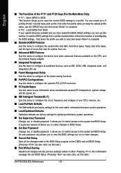
... a third party hardware monitor utility is installed. (Default: Disabled) (Note) This item is present only if you enter BIOS Setup. Use the up or down arrow key to select a device and press to 3 (Note) No-Execute Memory Protect (Note) CPU Enhanced Halt (C1E) (Note) CPU Thermal Monitor 2(TM2) (Note) CPU EIST Function (Note) Virtualization Technology (Note) Full Screen LOGO Show Init Display First [Press Enter] [Floppy] [Hard Disk] [CDROM] [Setup] [Disabled] [Enabled] [Disabled] [Enabled] [Enabled] [Enabled] [Enabled] [Enabled] [Enabled] [PCI] Item Help Menu Level` KLJI: Move...
... a third party hardware monitor utility is installed. (Default: Disabled) (Note) This item is present only if you enter BIOS Setup. Use the up or down arrow key to select a device and press to 3 (Note) No-Execute Memory Protect (Note) CPU Enhanced Halt (C1E) (Note) CPU Thermal Monitor 2(TM2) (Note) CPU EIST Function (Note) Virtualization Technology (Note) Full Screen LOGO Show Init Display First [Press Enter] [Floppy] [Hard Disk] [CDROM] [Setup] [Disabled] [Enabled] [Disabled] [Enabled] [Enabled] [Enabled] [Enabled] [Enabled] [Enabled] [PCI] Item Help Menu Level` KLJI: Move...
Manual
Page 38
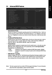
... as multiple virtual systems. (Default: Enabled) Full Screen LOGO Show Allows you install a CPU that support multi-processors mode. (Default: Enabled) Limit CPUID Max. English CPU Hyper-Threading (Note) Enables or disables Intel® Hyper-Threading Technology. PCI Sets the PCI graphics card as the first display. (Default) PEG Sets the PCI Express graphics card as Windows NT4.0. (Default: Disabled) No-Execute Memory Protect (Note) Enables or disables Intel® Execute Disable Bit function. Set this feature. When enabled, the CPU core frequency and voltage will be...
... as multiple virtual systems. (Default: Enabled) Full Screen LOGO Show Allows you install a CPU that support multi-processors mode. (Default: Enabled) Limit CPUID Max. English CPU Hyper-Threading (Note) Enables or disables Intel® Hyper-Threading Technology. PCI Sets the PCI graphics card as the first display. (Default) PEG Sets the PCI Express graphics card as Windows NT4.0. (Default: Disabled) No-Execute Memory Protect (Note) Enables or disables Intel® Execute Disable Bit function. Set this feature. When enabled, the CPU core frequency and voltage will be...

Manual
Page 39
...MS-DOS. (Default: Disabled) (Note) Supported on Windows® Vista® operating system only. - 39 - English 2-5 Integrated Peripherals CMOS Setup Utility-Copyright (C) 1984-2007 Award Software Integrated Peripherals SATA AHCI Mode SATA Port0-1 Native Mode USB Controller USB 2.0 Controller USB Keyboard Support USB Mouse Support Legacy USB storage detect Azalia Codec Onboard H/W LAN ` SMART LAN Onboard LAN Boot ROM Onboard IDE Controller Onboard Serial Port 1 Onboard Parallel Port Parallel Port Mode [Disabled] [Disabled] [Enabled] [Enabled] [Disabled] [Disabled] [Enabled] [Auto...
...MS-DOS. (Default: Disabled) (Note) Supported on Windows® Vista® operating system only. - 39 - English 2-5 Integrated Peripherals CMOS Setup Utility-Copyright (C) 1984-2007 Award Software Integrated Peripherals SATA AHCI Mode SATA Port0-1 Native Mode USB Controller USB 2.0 Controller USB Keyboard Support USB Mouse Support Legacy USB storage detect Azalia Codec Onboard H/W LAN ` SMART LAN Onboard LAN Boot ROM Onboard IDE Controller Onboard Serial Port 1 Onboard Parallel Port Parallel Port Mode [Disabled] [Disabled] [Enabled] [Enabled] [Disabled] [Disabled] [Enabled] [Auto...

Manual
Page 40
... USB storage detect Determines whether to detect USB storage devices, including USB flash drives and USB hard drives during the POST. (Default: Enabled) Azalia Codec Enables or disables the onboard audio function. (Default: Auto) If you wish to install a 3rd party add-in network card instead of using the onboard audio, set this item to Disabled. GA-P35-DS3L/S3L Motherboard - 40 - SMART LAN (LAN Cable Diagnostic Function) CMOS Setup Utility-Copyright (C) 1984-2007 Award Software SMART LAN Start detecting at a normal speed of 10/100/1000Mbps in Windows mode or when the LAN Boot ROM...
... USB storage detect Determines whether to detect USB storage devices, including USB flash drives and USB hard drives during the POST. (Default: Enabled) Azalia Codec Enables or disables the onboard audio function. (Default: Auto) If you wish to install a 3rd party add-in network card instead of using the onboard audio, set this item to Disabled. GA-P35-DS3L/S3L Motherboard - 40 - SMART LAN (LAN Cable Diagnostic Function) CMOS Setup Utility-Copyright (C) 1984-2007 Award Software SMART LAN Start detecting at a normal speed of 10/100/1000Mbps in Windows mode or when the LAN Boot ROM...

Manual
Page 41
... a cable problem occurs on Pair 1-2. Options are : 378/IRQ7 (default), 278/IRQ5, 3BC/IRQ7, Disabled. Parallel Port Mode Selects an operating mode for the onboard parallel (LPT) port. BIOS Setup Onboard LAN Boot ROM Allows you to decide whether to the fault or short. Options are not used in a 10/100 Mbps environment, so their Status fields will show Open, and the length shown is the approximate length of wires...
... a cable problem occurs on Pair 1-2. Options are : 378/IRQ7 (default), 278/IRQ5, 3BC/IRQ7, Disabled. Parallel Port Mode Selects an operating mode for the onboard parallel (LPT) port. BIOS Setup Onboard LAN Boot ROM Allows you to decide whether to the fault or short. Options are not used in a 10/100 Mbps environment, so their Status fields will show Open, and the length shown is the approximate length of wires...

Manual
Page 45
... chassis intrusion detection device attached to the motherboard CI header. When CPU temperature exceeds the threshold, BIOS will show "No" at next boot. (Default: Disabled) Case Opened Displays the detection status of previous chassis intrusion status. BIOS Setup Enabled clears the record of previous chassis intrusion status and the Case Opened field will show "No". If the system chassis cover is not connected or fails. Current CPU/SYSTEM/POWER FAN Speed (RPM) Displays current CPU/system/power fan speed. CPU/SYSTEM/POWER FAN...
... chassis intrusion detection device attached to the motherboard CI header. When CPU temperature exceeds the threshold, BIOS will show "No" at next boot. (Default: Disabled) Case Opened Displays the detection status of previous chassis intrusion status. BIOS Setup Enabled clears the record of previous chassis intrusion status and the Case Opened field will show "No". If the system chassis cover is not connected or fails. Current CPU/SYSTEM/POWER FAN Speed (RPM) Displays current CPU/system/power fan speed. CPU/SYSTEM/POWER FAN...
Manual
Page 46
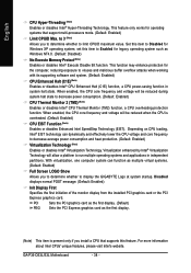
Auto Lets BIOS autodetect the type of CPU fan installed and sets the optimal CPU fan control mode. (Default) Voltage Sets Voltage mode for a 4-pin CPU fan. PWM Sets PWM mode for a 3-pin CPU fan. English CPU Smart FAN Control Enables or disables the CPU fan speed control function. This item is configurable only if CPU Smart FAN Control is not designed following Intel PWM fan specifications, selecting PWM mode may not effectively reduce the fan speed. If disabled, CPU fan runs at different speed according to control CPU fan speed. GA-P35-DS3L/S3L Motherboard - ...
Auto Lets BIOS autodetect the type of CPU fan installed and sets the optimal CPU fan control mode. (Default) Voltage Sets Voltage mode for a 4-pin CPU fan. PWM Sets PWM mode for a 3-pin CPU fan. English CPU Smart FAN Control Enables or disables the CPU fan speed control function. This item is configurable only if CPU Smart FAN Control is not designed following Intel PWM fan specifications, selecting PWM mode may not effectively reduce the fan speed. If disabled, CPU fan runs at different speed according to control CPU fan speed. GA-P35-DS3L/S3L Motherboard - ...

Manual
Page 47
...: Move Enter: Select F5: Previous Values +/-/PU/PD: Value F10: Save F6: Fail-Safe Defaults ESC: Exit F1: General Help F7: Optimized Defaults • Incorrectly doing overclock/overvoltage may result in system's failure to boot. mode based on system configurations. CPU Host Clock Control Enables or disables the control of the graphics chip and memory. BIOS Setup Enabled will allow for automated system reboot, or clear the CMOS values to reset the board to default values. (Default: Disabled...
...: Move Enter: Select F5: Previous Values +/-/PU/PD: Value F10: Save F6: Fail-Safe Defaults ESC: Exit F1: General Help F7: Optimized Defaults • Incorrectly doing overclock/overvoltage may result in system's failure to boot. mode based on system configurations. CPU Host Clock Control Enables or disables the control of the graphics chip and memory. BIOS Setup Enabled will allow for automated system reboot, or clear the CMOS values to reset the board to default values. (Default: Disabled...

Manual
Page 52
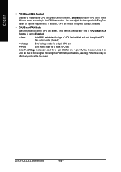
... the key. This exits the BIOS Setup without saving the changes made in BIOS Setup to the CMOS and exits the BIOS Setup program. This saves the changes to the CMOS. GA-P35-DS3L/S3L Motherboard - 52 - English 2-13 Save & Exit Setup CMOS Setup Utility-Copyright (C) 1984-2007 Award Software ` Standard CMOS Features Load Fail-Safe Defaults ` Advanced BIOS Features Load Optimized Defaults ` Integrated Peripherals Set Supervisor Password ` Power Management Setup Save to CMOS and EXIT (SYe/tNU)?seYr Password ` PnP/PCI Configurations Save & Exit Setup ` PC...
... the key. This exits the BIOS Setup without saving the changes made in BIOS Setup to the CMOS and exits the BIOS Setup program. This saves the changes to the CMOS. GA-P35-DS3L/S3L Motherboard - 52 - English 2-13 Save & Exit Setup CMOS Setup Utility-Copyright (C) 1984-2007 Award Software ` Standard CMOS Features Load Fail-Safe Defaults ` Advanced BIOS Features Load Optimized Defaults ` Integrated Peripherals Set Supervisor Password ` Power Management Setup Save to CMOS and EXIT (SYe/tNU)?seYr Password ` PnP/PCI Configurations Save & Exit Setup ` PC...

Manual
Page 77
... problems. (For reference only.) 1 short: System boots successfully 2 short: CMOS setting error 1 long, 1 short: Memory or motherboard error 1 long, 2 short: Monitor or graphics card error 1 long, 3 short: Keyboard error 1 long, 9 short: BIOS ROM error Continuous long beeps: Graphics card not inserted properly Continuous short beeps: Power error - 77 - Turn off your speaker is still on. Replace the battery. 4. Press to the steps below: Steps: 1. Q: What do the beeps emitted during the POST. A: Some advanced options are some BIOS options missing? Refer to enter BIOS Setup...
... problems. (For reference only.) 1 short: System boots successfully 2 short: CMOS setting error 1 long, 1 short: Memory or motherboard error 1 long, 2 short: Monitor or graphics card error 1 long, 3 short: Keyboard error 1 long, 9 short: BIOS ROM error Continuous long beeps: Graphics card not inserted properly Continuous short beeps: Power error - 77 - Turn off your speaker is still on. Replace the battery. 4. Press to the steps below: Steps: 1. Q: What do the beeps emitted during the POST. A: Some advanced options are some BIOS options missing? Refer to enter BIOS Setup...


