Manual
Page 1
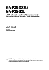
GA-P35-DS3L/ GA-P35-S3L LGA775 socket motherboard for Intel® CoreTM processor family/ Intel® Pentium® processor family/Intel® Celeron® processor family User's Manual Rev. 2001 12ME-P35DS3L-2001R * The WEEE marking on the product indicates this product must not be disposed of with user's other household waste and must be handed over to a designated collection point for the recycling of waste electrical and electronic equipment!! * The WEEE marking applies only in European Union's member states.
GA-P35-DS3L/ GA-P35-S3L LGA775 socket motherboard for Intel® CoreTM processor family/ Intel® Pentium® processor family/Intel® Celeron® processor family User's Manual Rev. 2001 12ME-P35DS3L-2001R * The WEEE marking on the product indicates this product must not be disposed of with user's other household waste and must be handed over to a designated collection point for the recycling of waste electrical and electronic equipment!! * The WEEE marking applies only in European Union's member states.

Manual
Page 2
Motherboard GA-P35-DS3L/GA-P35-S3L Jul. 31, 2007 Motherboard GA-P35-DS3L/GA-P35-S3L Jul. 31, 2007
Motherboard GA-P35-DS3L/GA-P35-S3L Jul. 31, 2007 Motherboard GA-P35-DS3L/GA-P35-S3L Jul. 31, 2007
Manual
Page 3
...manual are legally registered to the specifications and features in the use GIGABYTE's unique features, read the User's Manual. „ For instructions on your motherboard revision before updating motherboard BIOS, drivers, or when looking for technical information. The trademarks ... logo is designated by GIGABYTE without GIGABYTE's prior written permission. sive global distributor of GIGABYTE. For product-related information, check on our website at: http://www.gigabyte.com.tw Identifying Your Motherboard Revision The revision number on how to GIGABYTE UNITED INC. Example: ...
...manual are legally registered to the specifications and features in the use GIGABYTE's unique features, read the User's Manual. „ For instructions on your motherboard revision before updating motherboard BIOS, drivers, or when looking for technical information. The trademarks ... logo is designated by GIGABYTE without GIGABYTE's prior written permission. sive global distributor of GIGABYTE. For product-related information, check on our website at: http://www.gigabyte.com.tw Identifying Your Motherboard Revision The revision number on how to GIGABYTE UNITED INC. Example: ...
Manual
Page 4
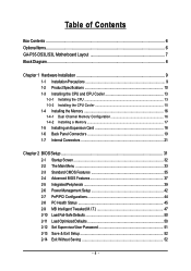
Table of Contents Box Contents ...6 OptionalItems ...6 GA-P35-DS3L/S3L Motherboard Layout 7 Block Diagram ...8 Chapter 1 Hardware Installation 9 1-1 Installation Precautions 9 1-2 Product Specifications 10 1-3 Installing the CPU and CPU Cooler 13 1-3-1 Installing the CPU 13 1-3-2 Installing the CPU ...
Table of Contents Box Contents ...6 OptionalItems ...6 GA-P35-DS3L/S3L Motherboard Layout 7 Block Diagram ...8 Chapter 1 Hardware Installation 9 1-1 Installation Precautions 9 1-2 Product Specifications 10 1-3 Installing the CPU and CPU Cooler 13 1-3-1 Installing the CPU 13 1-3-2 Installing the CPU ...
Manual
Page 6
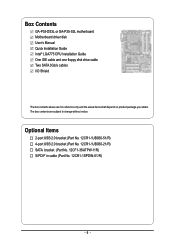
... USB 2.0 bracket (Part No. 12CR1-1UB030-21/R) SATA bracket (Part No. 12CF1-3SATPW-11R) S/PDIF in cable (Part No. 12CR1-1SPDIN-01/R) - 6 - Box Contents GA-P35-DS3L or GA-P35-S3L motherboard Motherboard driver disk User's Manual Quick Installation Guide Intel® LGA775 CPU Installation Guide One IDE cable and one floppy disk drive cable Two SATA...
... USB 2.0 bracket (Part No. 12CR1-1UB030-21/R) SATA bracket (Part No. 12CF1-3SATPW-11R) S/PDIF in cable (Part No. 12CR1-1SPDIN-01/R) - 6 - Box Contents GA-P35-DS3L or GA-P35-S3L motherboard Motherboard driver disk User's Manual Quick Installation Guide Intel® LGA775 CPU Installation Guide One IDE cable and one floppy disk drive cable Two SATA...

Manual
Page 7
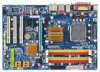
GA-P35-DS3L/S3L Motherboard Layout KB_MS COAXIAL OPTICAL ATX_12V LGA775 CPU_FAN ATX COM LPT DDRII1 GA-P35-DS3L/S3L R_USB SYS_FAN2 USB LAN F_AUDIO AUDIO SYS_FAN1 PCIE_3 RTL8111B PCIE_16 PCIE_1 SPDIF_O CODEC PCIE_2 SPDIF_I PCI1 PCI2 IT8718 PCI3 CD_IN Intel® P35 FDD DDRII3 DDRII4 DDRII2 PWR_FAN Intel® ICH9 BATTERY CLR_CMOS SATAII0 SATAII1 JMicron 368 SATAII4 BIOS SATAII5 IDE1 F_USB3 F_USB2 F_USB1 CI F_PANEL PWR_LED "*" Only the GA-P35-DS3L adopts All-Solid Capacitor design. - 7 -
GA-P35-DS3L/S3L Motherboard Layout KB_MS COAXIAL OPTICAL ATX_12V LGA775 CPU_FAN ATX COM LPT DDRII1 GA-P35-DS3L/S3L R_USB SYS_FAN2 USB LAN F_AUDIO AUDIO SYS_FAN1 PCIE_3 RTL8111B PCIE_16 PCIE_1 SPDIF_O CODEC PCIE_2 SPDIF_I PCI1 PCI2 IT8718 PCI3 CD_IN Intel® P35 FDD DDRII3 DDRII4 DDRII2 PWR_FAN Intel® ICH9 BATTERY CLR_CMOS SATAII0 SATAII1 JMicron 368 SATAII4 BIOS SATAII5 IDE1 F_USB3 F_USB2 F_USB1 CI F_PANEL PWR_LED "*" Only the GA-P35-DS3L adopts All-Solid Capacitor design. - 7 -
Manual
Page 9
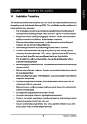
... electrostatic shielding container. • Before unplugging the power supply cable from the power outlet before installing or removing the motherboard or other hardware components. • When connecting hardware components to the internal connectors on the computer power during the ... process can become damaged as a result of electrostatic discharge (ESD). English Chapter 1 Hardware Installation 1-1 Installation Precautions The motherboard contains numerous delicate electronic circuits and components which can lead to damage to system components as well as physical harm to the...
... electrostatic shielding container. • Before unplugging the power supply cable from the power outlet before installing or removing the motherboard or other hardware components. • When connecting hardware components to the internal connectors on the computer power during the ... process can become damaged as a result of electrostatic discharge (ESD). English Chapter 1 Hardware Installation 1-1 Installation Precautions The motherboard contains numerous delicate electronic circuits and components which can lead to damage to system components as well as physical harm to the...
Manual
Page 10
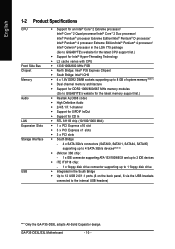
...Intel® Pentium® 4 processor/ Intel® Celeron® processor in the LGA 775 package (Go to GIGABYTE's website for the latest CPU support list.) Š Support for Intel® Hyper-Threading Technology Š L2... 1) Š Dual channel memory architecture Š Support for DDR2 1066/800/667 MHz memory modules (Go to GIGABYTE's website for the latest memory support list.) Š Realtek ALC888 codec Š High Definition Audio Š ...brackets connected to the internal USB headers) "*" Only the GA-P35-DS3L adopts All-Solid Capacitor design. GA-P35-DS3L/S3L Motherboard - 10 -
...Intel® Pentium® 4 processor/ Intel® Celeron® processor in the LGA 775 package (Go to GIGABYTE's website for the latest CPU support list.) Š Support for Intel® Hyper-Threading Technology Š L2... 1) Š Dual channel memory architecture Š Support for DDR2 1066/800/667 MHz memory modules (Go to GIGABYTE's website for the latest memory support list.) Š Realtek ALC888 codec Š High Definition Audio Š ...brackets connected to the internal USB headers) "*" Only the GA-P35-DS3L adopts All-Solid Capacitor design. GA-P35-DS3L/S3L Motherboard - 10 -
Manual
Page 12
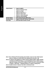
... SATA connectors for AHCI mode. (Refer to Chapter 2, "BIOS Setup," "Integrated Peripherals," for details on enabling AHCI.) (Note 3) Available functions in Easytune may differ by motherboard model. GA-P35-DS3L/S3L Motherboard - 12 -
... SATA connectors for AHCI mode. (Refer to Chapter 2, "BIOS Setup," "Integrated Peripherals," for details on enabling AHCI.) (Note 3) Available functions in Easytune may differ by motherboard model. GA-P35-DS3L/S3L Motherboard - 12 -
Manual
Page 13
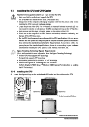
... if oriented incorrectly. (Or you wish to set beyond the standard specifications, please do so according to GIGABYTE's website for the peripherals. Locate the alignment keys on the motherboard CPU socket and the notches on the CPU Hardware Installation The CPU cannot be set the frequency beyond hardware...HT Technology • A chipset that supports HT Technology • An operating system that is optimized for HT Technology • A BIOS that the motherboard supports the CPU. (Go to your hardware specifications including the CPU, graphics card, memory, hard drive, etc.
... if oriented incorrectly. (Or you wish to set beyond the standard specifications, please do so according to GIGABYTE's website for the peripherals. Locate the alignment keys on the motherboard CPU socket and the notches on the CPU Hardware Installation The CPU cannot be set the frequency beyond hardware...HT Technology • A chipset that supports HT Technology • An operating system that is optimized for HT Technology • A BIOS that the motherboard supports the CPU. (Go to your hardware specifications including the CPU, graphics card, memory, hard drive, etc.

Manual
Page 14
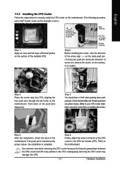
... the steps below to the CPU. Step 4: Hold the CPU with the socket alignment keys) and gently insert the CPU into its locked position. GA-P35-DS3L/S3L Motherboard - 14 - Align the CPU pin one marking (triangle) with the pin one corner of the CPU socket (or you may align the CPU notches... sure to turn off the computer and unplug the power cord from the power outlet to prevent damage to correctly install the CPU into the motherboard CPU socket. Step 5: Once the CPU is properly inserted, replace the load plate and push the CPU socket lever back into position. English B. Step ...
... the steps below to the CPU. Step 4: Hold the CPU with the socket alignment keys) and gently insert the CPU into its locked position. GA-P35-DS3L/S3L Motherboard - 14 - Align the CPU pin one marking (triangle) with the pin one corner of the CPU socket (or you may align the CPU notches... sure to turn off the computer and unplug the power cord from the power outlet to prevent damage to correctly install the CPU into the motherboard CPU socket. Step 5: Once the CPU is properly inserted, replace the load plate and push the CPU socket lever back into position. English B. Step ...
Manual
Page 15
...on the surface of the installed CPU. English 1-3-2 Installing the CPU Cooler Follow the steps below to correctly install the CPU cooler on the motherboard. (The following procedure uses Intel® boxed cooler as the picture above, the installation is to install.) Step 3: Place the cooler atop... on installing the cooler.) Step 5: After the installation, check the back of the motherboard. Inadequately removing the CPU cooler may adhere to your CPU cooler installation manual for instructions on the motherboard. Push down each push pin. Check that the Male and Female push pins are ...
...on the surface of the installed CPU. English 1-3-2 Installing the CPU Cooler Follow the steps below to correctly install the CPU cooler on the motherboard. (The following procedure uses Intel® boxed cooler as the picture above, the installation is to install.) Step 3: Place the cooler atop... on installing the cooler.) Step 5: After the installation, check the back of the motherboard. Inadequately removing the CPU cooler may adhere to your CPU cooler installation manual for instructions on the motherboard. Push down each push pin. Check that the Male and Female push pins are ...
Manual
Page 16
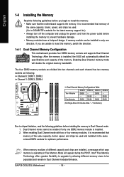
...Due to chipset limitation, read the following guidelines before you are unable to install the memory: • Make sure that the motherboard supports the memory. It is installed. 2. Enabling Dual Channel memory mode will appear during the POST. When enabling Dual Channel ... and unplug the power cord from the power outlet before installing the memory to GIGABYTE's website for optimum performance. Dual Channel mode cannot be used and installed in Dual Channel mode/performance. Four Modules DS/SS DS/SS DS/SS DDRII4 - GA-P35-DS3L/S3L Motherboard - 16 -
...Due to chipset limitation, read the following guidelines before you are unable to install the memory: • Make sure that the motherboard supports the memory. It is installed. 2. Enabling Dual Channel memory mode will appear during the POST. When enabling Dual Channel ... and unplug the power cord from the power outlet before installing the memory to GIGABYTE's website for optimum performance. Dual Channel mode cannot be used and installed in Dual Channel mode/performance. Four Modules DS/SS DS/SS DS/SS DDRII4 - GA-P35-DS3L/S3L Motherboard - 16 -
Manual
Page 17
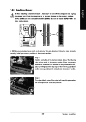
... DIMM A DDR2 memory module has a notch, so it vertically into place when the memory module is securely inserted. - 17 - Place the memory module on this motherboard. Step 2: The clips at both ends of the memory, push down on the left, place your memory modules in one direction. DDR2 DIMMs are not...
... DIMM A DDR2 memory module has a notch, so it vertically into place when the memory module is securely inserted. - 17 - Place the memory module on this motherboard. Step 2: The clips at both ends of the memory, push down on the left, place your memory modules in one direction. DDR2 DIMMs are not...
Manual
Page 18
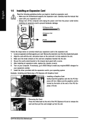
...your expansion card. • Always turn off the computer and unplug the power cord from the slot. Install the driver provided with your card. GA-P35-DS3L/S3L Motherboard - 18 - Locate an expansion slot that came with the expansion card in the slot. 3. Secure the card's metal bracket to the chassis back... and then pull the card straight up from the power outlet before you begin to install an expansion card: • Make sure the motherboard supports the expansion card. Turn on the card are completely inserted into the PCI Express x16 slot. Make sure the graphics card is fully...
...your expansion card. • Always turn off the computer and unplug the power cord from the slot. Install the driver provided with your card. GA-P35-DS3L/S3L Motherboard - 18 - Locate an expansion slot that came with the expansion card in the slot. 3. Secure the card's metal bracket to the chassis back... and then pull the card straight up from the power outlet before you begin to install an expansion card: • Make sure the motherboard supports the expansion card. Turn on the card are completely inserted into the PCI Express x16 slot. Make sure the graphics card is fully...
Manual
Page 19
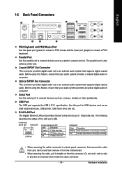
... is occurring • When removing the cable connected to a back panel connector, first remove the cable from your device and then remove it from the motherboard. • When removing the cable, pull it side to side to an external audio system that supports digital coaxial audio. Before using this feature, ensure...
... is occurring • When removing the cable connected to a back panel connector, first remove the cable from your device and then remove it from the motherboard. • When removing the cable, pull it side to side to an external audio system that supports digital coaxial audio. Before using this feature, ensure...
Manual
Page 20
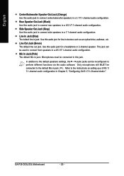
... configuration in jack. Use this audio jack for a headphone or 2-channel speaker. Microphones must be used to connect front speakers in a 4/5.1/7.1-channel audio configuration. GA-P35-DS3L/S3L Motherboard - 20 - English Center/Subwoofer Speaker Out Jack (Orange) Use this audio jack to connect center/subwoofer speakers in devices such as an optical drive, walkman...
... configuration in jack. Use this audio jack for a headphone or 2-channel speaker. Microphones must be used to connect front speakers in a 4/5.1/7.1-channel audio configuration. GA-P35-DS3L/S3L Motherboard - 20 - English Center/Subwoofer Speaker Out Jack (Orange) Use this audio jack to connect center/subwoofer speakers in devices such as an optical drive, walkman...
Manual
Page 21
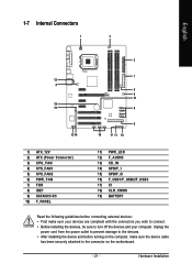
...) F_AUDIO 13) CD_IN 14) SPDIF_I 15) SPDIF_O 16) F_USB1/F_USB2/F_USB3 17) CI 18) CLR_CMOS 19) BATTERY Read the following guidelines before turning on the motherboard. - 21 - Hardware Installation Unplug the power cord from the power outlet to prevent damage to the devices. • After installing the device and before connecting...
...) F_AUDIO 13) CD_IN 14) SPDIF_I 15) SPDIF_O 16) F_USB1/F_USB2/F_USB3 17) CI 18) CLR_CMOS 19) BATTERY Read the following guidelines before turning on the motherboard. - 21 - Hardware Installation Unplug the power cord from the power outlet to prevent damage to the devices. • After installing the device and before connecting...

Manual
Page 22
...-12V GND PS_ON(soft On/Off) GND GND GND -5V +5V +5V +5V (Only for 2x12-pinATX) GND (Only for 2x12-pin ATX) GA-P35-DS3L/S3L Motherboard - 22 - Do not insert the power supply cable into pins under the protective cover when using a 2x12 power supply, remove the protective cover from... connector possesses a foolproof design. Before connecting the power connector, first make sure the power supply is turned off and all the components on the motherboard. If the 12V power connector is not connected, the computer will not start. • To meet expansion requirements, it is recommended that a ...
...-12V GND PS_ON(soft On/Off) GND GND GND -5V +5V +5V +5V (Only for 2x12-pinATX) GND (Only for 2x12-pin ATX) GA-P35-DS3L/S3L Motherboard - 22 - Do not insert the power supply cable into pins under the protective cover when using a 2x12 power supply, remove the protective cover from... connector possesses a foolproof design. Before connecting the power connector, first make sure the power supply is turned off and all the components on the motherboard. If the 12V power connector is not connected, the computer will not start. • To meet expansion requirements, it is recommended that a ...
Manual
Page 23
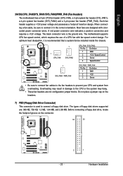
A red power connector wire indicates a positive connection and requires a +12V voltage. The motherboard supports CPU fan speed control, which requires the use of floppy disk drives supported are: 360 KB, 720 KB, 1.2 MB, 1.44 MB, and 2.88 MB. ... the foolproof groove on the headers. 7) FDD (Floppy Disk Drive Connector) This connector is the ground wire. English 3/4/5/6) CPU_FAN/SYS_FAN1/SYS_FAN2/PWR_FAN (Fan Headers) The motherboard has a 4-pin CPU fan header (CPU_FAN), a 3-pin system fan header (SYS_FAN1), a 4-pin system fan header (SYS_FAN2) and a 3-pin power fan header (PWR_FAN...
A red power connector wire indicates a positive connection and requires a +12V voltage. The motherboard supports CPU fan speed control, which requires the use of floppy disk drives supported are: 360 KB, 720 KB, 1.2 MB, 1.44 MB, and 2.88 MB. ... the foolproof groove on the headers. 7) FDD (Floppy Disk Drive Connector) This connector is the ground wire. English 3/4/5/6) CPU_FAN/SYS_FAN1/SYS_FAN2/PWR_FAN (Fan Headers) The motherboard has a 4-pin CPU fan header (CPU_FAN), a 3-pin system fan header (SYS_FAN1), a 4-pin system fan header (SYS_FAN2) and a 3-pin power fan header (PWR_FAN...


