Manual
Page 1
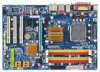
GA-P35-DS3L/ GA-P35-S3L LGA775 socket motherboard for Intel® CoreTM processor family/ Intel® Pentium® processor family/Intel® Celeron® processor family User's Manual Rev. 2001 12ME-P35DS3L-2001R * The WEEE marking on the product indicates this product must not be disposed of with user's other household waste and must be handed over to a designated collection point for the recycling of waste electrical and electronic equipment!! * The WEEE marking applies only in European Union's member states.
GA-P35-DS3L/ GA-P35-S3L LGA775 socket motherboard for Intel® CoreTM processor family/ Intel® Pentium® processor family/Intel® Celeron® processor family User's Manual Rev. 2001 12ME-P35DS3L-2001R * The WEEE marking on the product indicates this product must not be disposed of with user's other household waste and must be handed over to a designated collection point for the recycling of waste electrical and electronic equipment!! * The WEEE marking applies only in European Union's member states.
Manual
Page 3
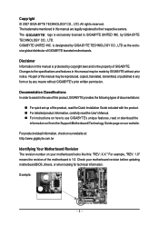
.... Check your motherboard looks like this manual are legally registered to use of this manual is protected by copyright laws and is 1.0. Example: - 3 - The trademarks mentioned in any form or by GIGABYTE without GIGABYTE's prior written permission. is exclusively licensed... in this : "REV: X.X." Disclaimer Information in the use GIGABYTE's unique features, read the User's Manual. „ For instructions on our website. Documentation Classifications In order to assist in this product, GIGABYTE provides the following types of documentations: „ For quick set...
.... Check your motherboard looks like this manual are legally registered to use of this manual is protected by copyright laws and is 1.0. Example: - 3 - The trademarks mentioned in any form or by GIGABYTE without GIGABYTE's prior written permission. is exclusively licensed... in this : "REV: X.X." Disclaimer Information in the use GIGABYTE's unique features, read the User's Manual. „ For instructions on our website. Documentation Classifications In order to assist in this product, GIGABYTE provides the following types of documentations: „ For quick set...
Manual
Page 6
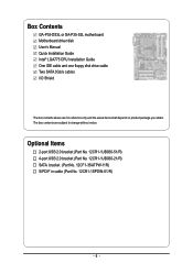
... No. 12CR1-1UB030-21/R) SATA bracket (Part No. 12CF1-3SATPW-11R) S/PDIF in cable (Part No. 12CR1-1SPDIN-01/R) - 6 - Box Contents GA-P35-DS3L or GA-P35-S3L motherboard Motherboard driver disk User's Manual Quick Installation Guide Intel® LGA775 CPU Installation Guide One IDE cable and one floppy disk drive cable Two SATA 3Gb/s cables...
... No. 12CR1-1UB030-21/R) SATA bracket (Part No. 12CF1-3SATPW-11R) S/PDIF in cable (Part No. 12CR1-1SPDIN-01/R) - 6 - Box Contents GA-P35-DS3L or GA-P35-S3L motherboard Motherboard driver disk User's Manual Quick Installation Guide Intel® LGA775 CPU Installation Guide One IDE cable and one floppy disk drive cable Two SATA 3Gb/s cables...
Manual
Page 9
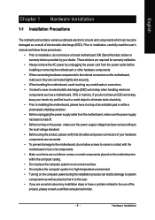
... installing the motherboard, please have a problem related to the use of the product, please consult a certified computer technician. - 9 - Prior to installation, carefully read the user's manual and follow these procedures: • Prior to installation, do not remove or break motherboard S/N (Serial Number) sticker or warranty sticker provided by unplugging the power...
... installing the motherboard, please have a problem related to the use of the product, please consult a certified computer technician. - 9 - Prior to installation, carefully read the user's manual and follow these procedures: • Prior to installation, do not remove or break motherboard S/N (Serial Number) sticker or warranty sticker provided by unplugging the power...
Manual
Page 15
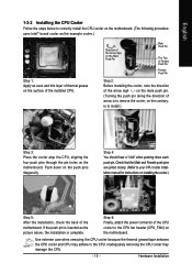
... thermal grease on the surface of the motherboard. Hardware Installation Step 6: Finally, attach the power connector of the CPU cooler to your CPU cooler installation manual for instructions on installing the cooler.) Step 5: After the installation, check the back of the installed CPU. Check that the Male and Female push pins...
... thermal grease on the surface of the motherboard. Hardware Installation Step 6: Finally, attach the power connector of the CPU cooler to your CPU cooler installation manual for instructions on installing the cooler.) Step 5: After the installation, check the back of the installed CPU. Check that the Male and Female push pins...
Manual
Page 18
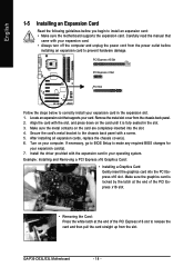
... begin to install an expansion card: • Make sure the motherboard supports the expansion card. Install the driver provided with a screw. 5. GA-P35-DS3L/S3L Motherboard - 18 - PCI Express x16 Slot PCI Express x1 Slot PCI Slot Follow the steps below to correctly install your card. Example:...Removing a PCI Express x16 Graphics Card: • Installing a Graphics Card: Gently insert the graphics card into the slot. 4. Carefully read the manual that supports your expansion card in the slot. 3. Align the card with your operating system. Make sure the metal contacts on the card are ...
... begin to install an expansion card: • Make sure the motherboard supports the expansion card. Install the driver provided with a screw. 5. GA-P35-DS3L/S3L Motherboard - 18 - PCI Express x16 Slot PCI Express x1 Slot PCI Slot Follow the steps below to correctly install your card. Example:...Removing a PCI Express x16 Graphics Card: • Installing a Graphics Card: Gently insert the graphics card into the slot. 4. Carefully read the manual that supports your expansion card in the slot. 3. Align the card with your operating system. Make sure the metal contacts on the card are ...

Manual
Page 28
... about connecting the S/PDIF digital audio cable, carefully read the manual for your motherboard to USB 2.0/1.1 specification. Each USB header can provide two USB ports via an optional USB bracket. For purchasing the optional USB bracket, please contact the local dealer. GA-P35-DS3L/S3L Motherboard - 28 - English 15) SPDIF_O (S/PDIF Out Header) This...
... about connecting the S/PDIF digital audio cable, carefully read the manual for your motherboard to USB 2.0/1.1 specification. Each USB header can provide two USB ports via an optional USB bracket. For purchasing the optional USB bracket, please contact the local dealer. GA-P35-DS3L/S3L Motherboard - 28 - English 15) SPDIF_O (S/PDIF Out Header) This...

Manual
Page 29
... do so may cause damage to the motherboard. • After system restart, go to BIOS Setup to load factory defaults (select Load Optimized Defaults) or manually configure the BIOS settings (refer to touch the two pins for BIOS configurations). - 29 - Definition 1 1 Signal 2 GND 18) CLR_CMOS (Clearing CMOS Jumper) Use this jumper...
... do so may cause damage to the motherboard. • After system restart, go to BIOS Setup to load factory defaults (select Load Optimized Defaults) or manually configure the BIOS settings (refer to touch the two pins for BIOS configurations). - 29 - Definition 1 1 Signal 2 GND 18) CLR_CMOS (Clearing CMOS Jumper) Use this jumper...
Manual
Page 35
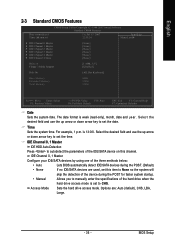
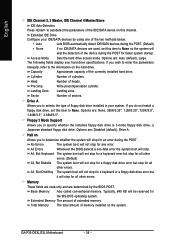
... of the three methods below: • Auto Lets BIOS automatically detect IDE/SATA devices during the POST for faster system startup. • Manual Allows you to None so the system will skip the detection of the hard drive when the hard drive access mode is 13:0:0. IDE Channel... 0, 1 Master IDE HDD Auto-Detection Press to autodetect the parameters of the IDE/SATA device on this item to manually enter the specifications of the device during the POST. (Default) • None If no IDE/SATA devices are : Auto (default), CHS, LBA, Large. - ...
... of the three methods below: • Auto Lets BIOS automatically detect IDE/SATA devices during the POST for faster system startup. • Manual Allows you to None so the system will skip the detection of the hard drive when the hard drive access mode is 13:0:0. IDE Channel... 0, 1 Master IDE HDD Auto-Detection Press to autodetect the parameters of the IDE/SATA device on this item to manually enter the specifications of the device during the POST. (Default) • None If no IDE/SATA devices are : Auto (default), CHS, LBA, Large. - ...
Manual
Page 36
...called conventional memory. Drive A Allows you to selects the type of the currently installed hard drive. If you wish to enter the parameters manually, refer to specify whether the installed floppy disk drive is 3-mode floppy disk drive, a Japanese standard floppy disk drive. All, But ...this item to None so the system will be reserved for faster system startup. Extended Memory The amount of memory installed on the system. GA-P35-DS3L/S3L Motherboard - 36 - All, But Keyboard The system boot will not stop for all other errors. Extended IDE Drive Configure your hard...
...called conventional memory. Drive A Allows you to selects the type of the currently installed hard drive. If you wish to enter the parameters manually, refer to specify whether the installed floppy disk drive is 3-mode floppy disk drive, a Japanese standard floppy disk drive. All, But ...this item to None so the system will be reserved for faster system startup. Extended Memory The amount of memory installed on the system. GA-P35-DS3L/S3L Motherboard - 36 - All, But Keyboard The system boot will not stop for all other errors. Extended IDE Drive Configure your hard...

Manual
Page 47
... PCI-E OverVoltage Control FSB OverVoltage Control (G)MCH OverVoltage Control CPU Voltage Control Normal CPU Vcore ******** [Auto] [18X] [Disabled] 200 [Auto] [Disabled] [Turbo] [Auto] 800 [Option 1] [Manual] [Normal] [Normal] [Normal] [Normal] [Normal] 1.38750V Item Help Menu Level` KLJI: Move Enter: Select F5: Previous Values +/-/PU/PD: Value F10: Save F6: Fail-Safe...
... PCI-E OverVoltage Control FSB OverVoltage Control (G)MCH OverVoltage Control CPU Voltage Control Normal CPU Vcore ******** [Auto] [18X] [Disabled] 200 [Auto] [Disabled] [Turbo] [Auto] 800 [Option 1] [Manual] [Normal] [Normal] [Normal] [Normal] [Normal] 1.38750V Item Help Menu Level` KLJI: Move Enter: Select F5: Previous Values +/-/PU/PD: Value F10: Save F6: Fail-Safe...

Manual
Page 48
... High Speed DRAM DLL Settings Provides two different memory timing configurations. Increases CPU frequency by 9% or 11% depending on CPU loading. GA-P35-DS3L/S3L Motherboard - 48 - Standard Turbo Lets the system operate at three different performance levels. Auto sets memory multiplier according to the ...or Option 2 to 200 MHz. This item is configurable only if the CPU Host Clock Control option is from 90 MHz to manually set the CPU host frequency. For an 800 MHz FSB CPU, set the system memory multiplier. The adjustable range is enabled. ...
... High Speed DRAM DLL Settings Provides two different memory timing configurations. Increases CPU frequency by 9% or 11% depending on CPU loading. GA-P35-DS3L/S3L Motherboard - 48 - Standard Turbo Lets the system operate at three different performance levels. Auto sets memory multiplier according to the ...or Option 2 to 200 MHz. This item is configurable only if the CPU Host Clock Control option is from 90 MHz to manually set the CPU host frequency. For an 800 MHz FSB CPU, set the system memory multiplier. The adjustable range is enabled. ...

Manual
Page 49
English System Voltage Control Determines whether to manually set PCIe voltage. Normal Supplies the FSB voltage as required. The adjustable range is dependent on the CPU being installed. (Default: Normal) Note: Increasing CPU ... Bridge voltage by 0.1V to set memory voltage. CPU Voltage Control Allows you to set the Front Side Bus voltage. Manual allows all voltage control items below to be configurable. (Default: Manual) DDR2 OverVoltage Control Allows you to set the North Bridge voltage. Normal CPU Vcore Displays the normal operating voltage of...
English System Voltage Control Determines whether to manually set PCIe voltage. Normal Supplies the FSB voltage as required. The adjustable range is dependent on the CPU being installed. (Default: Normal) Note: Increasing CPU ... Bridge voltage by 0.1V to set memory voltage. CPU Voltage Control Allows you to set the Front Side Bus voltage. Manual allows all voltage control items below to be configurable. (Default: Manual) DDR2 OverVoltage Control Allows you to set the North Bridge voltage. Normal CPU Vcore Displays the normal operating voltage of...

Manual
Page 55
Drivers Installation English 3-4 Hardware Information This page provides information about the hardware devices on this motherboard. 3-5 Contact Us Check the contacts information of the GIGABYTE headquarter in Taiwan and the overseas branch offices on the last page of this manual. - 55 -
Drivers Installation English 3-4 Hardware Information This page provides information about the hardware devices on this motherboard. 3-5 Contact Us Check the contacts information of the GIGABYTE headquarter in Taiwan and the overseas branch offices on the last page of this manual. - 55 -
Manual
Page 66
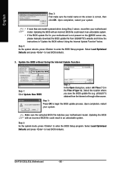
... make sure the model name on the @BIOS server site, please manually download the BIOS update file from the Internet or through other source.... 1: Click Update New BIOS. Step 3: Press OK to load BIOS defaults. 3. p35ds3l.f1) obtained from GIGABYTE's website and follow the instructions in an unbootable system. Upon completion, restart your motherboard model. Step 4: As...could result in the Files of type list. Select the location where you save the BIOS update file (e.g. GA-P35-DS3L/S3L Motherboard - 66 - Upon completion, restart your system. • If more than one model is...
... make sure the model name on the @BIOS server site, please manually download the BIOS update file from the Internet or through other source.... 1: Click Update New BIOS. Step 3: Press OK to load BIOS defaults. 3. p35ds3l.f1) obtained from GIGABYTE's website and follow the instructions in an unbootable system. Upon completion, restart your motherboard model. Step 4: As...could result in the Files of type list. Select the location where you save the BIOS update file (e.g. GA-P35-DS3L/S3L Motherboard - 66 - Upon completion, restart your system. • If more than one model is...
Manual
Page 69
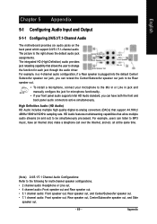
... speaker out, Center/Subwoofer speaker out, and Side speaker out. - 69 - Appendix HD Audio features multistreaming capabilities that allow multiple audio streams (in jack and manually configure the jack for each jack through the audio driver. English Chapter 5 Appendix 5-1 Configuring Audio Input and Output 5-1-1 Configuring 2/4/5.1/7.1-Channel Audio The motherboard provides six...
... speaker out, Center/Subwoofer speaker out, and Side speaker out. - 69 - Appendix HD Audio features multistreaming capabilities that allow multiple audio streams (in jack and manually configure the jack for each jack through the audio driver. English Chapter 5 Appendix 5-1 Configuring Audio Input and Output 5-1-1 Configuring 2/4/5.1/7.1-Channel Audio The motherboard provides six...


