
Manual
Page 3
... may be made by any form or by GIGABYTE without GIGABYTE's prior written permission. Documentation Classifications In order to their respective owners. For product-related information, check on our website at: http://www.gigabyte.com Identifying Your Motherboard Revision The revision number... on your motherboard revision before updating motherboard BIOS, drivers, or when looking for technical information. All rights reserved. The trademarks...
... may be made by any form or by GIGABYTE without GIGABYTE's prior written permission. Documentation Classifications In order to their respective owners. For product-related information, check on our website at: http://www.gigabyte.com Identifying Your Motherboard Revision The revision number... on your motherboard revision before updating motherboard BIOS, drivers, or when looking for technical information. All rights reserved. The trademarks...
Manual
Page 4
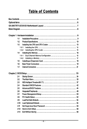
Table of Contents Box Contents ...6 OptionalItems ...6 GA-MA770T-UD3/US3 Motherboard Layout 7 Block Diagram ...8 Chapter 1 Hardware Installation 9 1-1 Installation Precautions 9 1-2 Product Specifications 10 1-3 Installing the CPU and CPU ... Installing an Expansion Card 18 1-6 Back Panel Connectors 19 1-7 Internal Connectors 21 Chapter 2 BIOS Setup 33 2-1 Startup Screen 34 2-2 The Main Menu 35 2-3 MB Intelligent Tweaker(M.I.T 37 2-4 Standard CMOS Features 42 2-5 Advanced BIOS Features 44 2-6 IntegratedPeripherals 46 2-7 Power Management Setup 50 2-8 PC Health Status 52 2-9 Load...
Table of Contents Box Contents ...6 OptionalItems ...6 GA-MA770T-UD3/US3 Motherboard Layout 7 Block Diagram ...8 Chapter 1 Hardware Installation 9 1-1 Installation Precautions 9 1-2 Product Specifications 10 1-3 Installing the CPU and CPU ... Installing an Expansion Card 18 1-6 Back Panel Connectors 19 1-7 Internal Connectors 21 Chapter 2 BIOS Setup 33 2-1 Startup Screen 34 2-2 The Main Menu 35 2-3 MB Intelligent Tweaker(M.I.T 37 2-4 Standard CMOS Features 42 2-5 Advanced BIOS Features 44 2-6 IntegratedPeripherals 46 2-7 Power Management Setup 50 2-8 PC Health Status 52 2-9 Load...

Manual
Page 5
... 58 3-3 Technical Manuals 58 3-4 Contact ...59 3-5 System ...59 3-6 Download Center 60 Chapter 4 Unique Features 61 4-1 Xpress Recovery2 61 4-2 BIOS Update Utilities 64 4-2-1 Updating the BIOS with the Q-Flash Utility 64 4-2-2 Updating the BIOS with the @BIOS Utility 67 4-3 EasyTune 6 ...68 4-4 Easy Energy Saver 69 4-5 Q-Share ...71 4-6 Time Repair ...72 Chapter 5 Appendix ...73 5-1 Configuring SATA...
... 58 3-3 Technical Manuals 58 3-4 Contact ...59 3-5 System ...59 3-6 Download Center 60 Chapter 4 Unique Features 61 4-1 Xpress Recovery2 61 4-2 BIOS Update Utilities 64 4-2-1 Updating the BIOS with the Q-Flash Utility 64 4-2-2 Updating the BIOS with the @BIOS Utility 67 4-3 EasyTune 6 ...68 4-4 Easy Energy Saver 69 4-5 Q-Share ...71 4-6 Time Repair ...72 Chapter 5 Appendix ...73 5-1 Configuring SATA...
Manual
Page 8
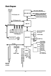
Block Diagram PCIe CLK (100 MHz) 1 PCI Express x16 PCI Express x16 CPU CLK+/-(200 MHz) AM3+/AM3 CPU DDR3 1666(O.C.)/1333/1066 MHz Dual Channel Memory Hyper Transport 3.0 PCI Express Bus x1 x1 x1 x1 AMD 770 PCIe CLK x1 (100 MHz) 4 PCI Express x1 RTL8111D/E RJ45 LAN PCI Bus TSB43AB23 3 IEEE 1394a AMD SB710 CODEC ATA-133/100/66/33 IDE Channel 6 SATA 3Gb/s 12 USB Ports IT8720 Dual BIOS Floppy LPT Port COM Port PS/2 KB/Mouse Surround Speaker Out Center/Subwoofer Speaker Out Side Speaker Out MIC Line Out Line In S/PDIF In S/PDIF Out 2 PCI PCI CLK (33 MHz) - 8 -
Block Diagram PCIe CLK (100 MHz) 1 PCI Express x16 PCI Express x16 CPU CLK+/-(200 MHz) AM3+/AM3 CPU DDR3 1666(O.C.)/1333/1066 MHz Dual Channel Memory Hyper Transport 3.0 PCI Express Bus x1 x1 x1 x1 AMD 770 PCIe CLK x1 (100 MHz) 4 PCI Express x1 RTL8111D/E RJ45 LAN PCI Bus TSB43AB23 3 IEEE 1394a AMD SB710 CODEC ATA-133/100/66/33 IDE Channel 6 SATA 3Gb/s 12 USB Ports IT8720 Dual BIOS Floppy LPT Port COM Port PS/2 KB/Mouse Surround Speaker Out Center/Subwoofer Speaker Out Side Speaker Out MIC Line Out Line In S/PDIF In S/PDIF Out 2 PCI PCI CLK (33 MHz) - 8 -

Manual
Page 11
... CPU/System/Power fan speed detection CPU overheating warning CPU/System/Power fan fail warning CPU/System fan speed control (Note 4) BIOS 2 x 16 Mbit flash Use of licensed AWARD BIOS Support for DualBIOSTM PnP 1.0a, DMI 2.0, SM...
... CPU/System/Power fan speed detection CPU overheating warning CPU/System/Power fan fail warning CPU/System fan speed control (Note 4) BIOS 2 x 16 Mbit flash Use of licensed AWARD BIOS Support for DualBIOSTM PnP 1.0a, DMI 2.0, SM...
Manual
Page 12
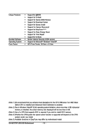
Unique Features Bundled Software Operating System Form Factor Support for @BIOS Support for Q-Flash Support for Xpress BIOS Rescue Support for Download Center Support for Xpress Install Support for Xpress Recovery2 Support for EasyTune (Note 5) Support for Easy ... fan speed control function is supported will depend on the CPU/ system cooler you install. (Note 5) Available functions in EasyTune may differ by motherboard model. GA-MA770T-UD3/US3 Motherboard - 12 -
Unique Features Bundled Software Operating System Form Factor Support for @BIOS Support for Q-Flash Support for Xpress BIOS Rescue Support for Download Center Support for Xpress Install Support for Xpress Recovery2 Support for EasyTune (Note 5) Support for Easy ... fan speed control function is supported will depend on the CPU/ system cooler you install. (Note 5) Available functions in EasyTune may differ by motherboard model. GA-MA770T-UD3/US3 Motherboard - 12 -
Manual
Page 16
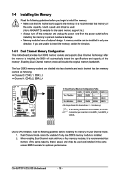
...and capacity of the same capacity, brand, speed, and chips be used . (Go to GIGABYTE's website for optimum performance. DS/SS DS/SS Four Modules DS/SS DS/SS DS/SS...one DDR3 memory module is recommended that the motherboard supports the memory. It is installed. 2. GA-MA770T-UD3/US3 Motherboard - 16 - After the memory is recommended that you begin to CPU limitation, .... When enabling Dual Channel mode with two or four memory modules, it is installed, the BIOS will double the original memory bandwidth. DDR3_1 DDR3_2 DDR3_3 DDR3_4 Due to install the memory: • Make ...
...and capacity of the same capacity, brand, speed, and chips be used . (Go to GIGABYTE's website for optimum performance. DS/SS DS/SS Four Modules DS/SS DS/SS DS/SS...one DDR3 memory module is recommended that the motherboard supports the memory. It is installed. 2. GA-MA770T-UD3/US3 Motherboard - 16 - After the memory is recommended that you begin to CPU limitation, .... When enabling Dual Channel mode with two or four memory modules, it is installed, the BIOS will double the original memory bandwidth. DDR3_1 DDR3_2 DDR3_3 DDR3_4 Due to install the memory: • Make ...
Manual
Page 18
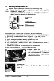
...install an expansion card: • Make sure the motherboard supports the expansion card. After installing all expansion cards, replace the chassis cover(s). 6. GA-MA770T-UD3/US3 Motherboard - 18 - Install the driver provided with a screw. 5. Make sure the card is securely seated in your expansion card. &#...on the top edge of the card until it is fully seated in the expansion slot. 1. If necessary, go to BIOS Setup to make any required BIOS changes for your computer. Example: Installing and Removing a PCI Express x16 Graphics Card: • Installing a Graphics Card: ...
...install an expansion card: • Make sure the motherboard supports the expansion card. After installing all expansion cards, replace the chassis cover(s). 6. GA-MA770T-UD3/US3 Motherboard - 18 - Install the driver provided with a screw. 5. Make sure the card is securely seated in your expansion card. &#...on the top edge of the card until it is fully seated in the expansion slot. 1. If necessary, go to BIOS Setup to make any required BIOS changes for your computer. Example: Installing and Removing a PCI Express x16 Graphics Card: • Installing a Graphics Card: ...

Manual
Page 25
... state or powered off . Turn off your computer and unplug the power cord. 2. The LED is on the chassis to keep the values (such as BIOS configurations, date, and time information) in the CMOS when the computer is in accordance with local environmental regulations. - 25 -
... state or powered off . Turn off your computer and unplug the power cord. 2. The LED is on the chassis to keep the values (such as BIOS configurations, date, and time information) in the CMOS when the computer is in accordance with local environmental regulations. - 25 -
Manual
Page 26
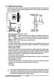
PW+ PWSPEAK+ SPEAK- 2 20 1 19 HD+ HD- GA-MA770T-UD3/US3 Motherboard - 26 - Message/Power/ Power Sleep LED Switch Speaker MSG+ MSG- The S0 On LED is... when S1 Blinking the system is detected at system startup. When connecting your system using the power switch (refer to Chapter 2, "BIOS Setup," "Power Management Setup," for information about beep codes. • HD (Hard Drive Activity LED, Blue) Connects to the speaker... No connection The front panel design may configure the way to turn off when the system is detected, the BIOS may issue beeps in S1 sleep state.
PW+ PWSPEAK+ SPEAK- 2 20 1 19 HD+ HD- GA-MA770T-UD3/US3 Motherboard - 26 - Message/Power/ Power Sleep LED Switch Speaker MSG+ MSG- The S0 On LED is... when S1 Blinking the system is detected at system startup. When connecting your system using the power switch (refer to Chapter 2, "BIOS Setup," "Power Management Setup," for information about beep codes. • HD (Hard Drive Activity LED, Blue) Connects to the speaker... No connection The front panel design may configure the way to turn off when the system is detected, the BIOS may issue beeps in S1 sleep state.

Manual
Page 31
Open: Normal Short: Clear CMOS Values • Always turn off your computer and unplug the power cord from the jumper. date information and BIOS configurations) and reset the CMOS values to remove the jumper cap from the power outlet before clearing the CMOS values. • After clearing the ...CMOS values and before turning on the two pins to temporarily short the two pins or use a metal object like a screwdriver to Chapter 2, "BIOS Setup," for a few seconds. To clear the CMOS values, place a jumper cap on your computer, be sure to factory defaults. Failure to do so ...
Open: Normal Short: Clear CMOS Values • Always turn off your computer and unplug the power cord from the jumper. date information and BIOS configurations) and reset the CMOS values to remove the jumper cap from the power outlet before clearing the CMOS values. • After clearing the ...CMOS values and before turning on the two pins to temporarily short the two pins or use a metal object like a screwdriver to Chapter 2, "BIOS Setup," for a few seconds. To clear the CMOS values, place a jumper cap on your computer, be sure to factory defaults. Failure to do so ...

Manual
Page 33
... or to quickly and easily upgrade or back up BIOS without entering the operating system. • @BIOS is a Windows-based utility that searches and downloads the latest version of BIOS from the Internet and updates the BIOS. To upgrade the BIOS, use either the GIGABYTE Q-Flash or @BIOS utility. • Q-Flash allows the user to activate certain...
... or to quickly and easily upgrade or back up BIOS without entering the operating system. • @BIOS is a Windows-based utility that searches and downloads the latest version of BIOS from the Internet and updates the BIOS. To upgrade the BIOS, use either the GIGABYTE Q-Flash or @BIOS utility. • Q-Flash allows the user to activate certain...

Manual
Page 34
... during the POST. To show the BIOS POST screen. A. The POST Screen Award Modular BIOS v6.00PG, An Energy Star Ally Copyright (C) 1984-2009, Award Software, Inc. The LOGO Screen (Default) B. You can be used for GA-MA770T-UD3 E1 . . . . : BIOS Setup : XpressRecovery2 : Boot Menu :...00 Function Keys Function Keys Function Keys: : POST SCREEN Press the key to show the BIOS POST screen at system startup, refer to enter BIOS Setup first. Note: The setting in Boot Menu. GA-MA770T-UD3/US3 Motherboard - 34 - To exit Boot Menu, press . For more information, refer...
... during the POST. To show the BIOS POST screen. A. The POST Screen Award Modular BIOS v6.00PG, An Energy Star Ally Copyright (C) 1984-2009, Award Software, Inc. The LOGO Screen (Default) B. You can be used for GA-MA770T-UD3 E1 . . . . : BIOS Setup : XpressRecovery2 : Boot Menu :...00 Function Keys Function Keys Function Keys: : POST SCREEN Press the key to show the BIOS POST screen at system startup, refer to enter BIOS Setup first. Note: The setting in Boot Menu. GA-MA770T-UD3/US3 Motherboard - 34 - To exit Boot Menu, press . For more information, refer...

Manual
Page 35
...the screen. Use arrow keys to move among the items and press to accept or enter a sub-menu. (Sample BIOS Version: GA-MA770T-UD3 E1) CMOS Setup Utility-Copyright (C) 1984-2009 Award Software MB Intelligent Tweaker(M.I.T.) Standard CMOS Features Advanced... BIOS Features Integrated Peripherals Power Management Setup PC Health Status Load Fail-Safe Defaults Load Optimized ...
...the screen. Use arrow keys to move among the items and press to accept or enter a sub-menu. (Sample BIOS Version: GA-MA770T-UD3 E1) CMOS Setup Utility-Copyright (C) 1984-2009 Award Software MB Intelligent Tweaker(M.I.T.) Standard CMOS Features Advanced... BIOS Features Integrated Peripherals Power Management Setup PC Health Status Load Fail-Safe Defaults Load Optimized ...
Manual
Page 36
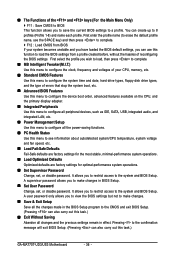
... MB Intelligent Tweaker(M.I.T.) Use this menu to configure the clock, frequency and voltages of your system becomes unstable and you have loaded the BIOS default settings, you to make changes. Save & Exit Setup Save all changes and the previous settings remain in effect. A supervisor... keys (For the Main Menu Only) F11 : Save CMOS to BIOS This function allows you to view the BIOS settings but not to make changes in BIOS Setup. Set User Password Change, set , or disable password. You can also carry out this task.) GA-MA770T-UD3/US3 Motherboard - 36 -
... MB Intelligent Tweaker(M.I.T.) Use this menu to configure the clock, frequency and voltages of your system becomes unstable and you have loaded the BIOS default settings, you to make changes. Save & Exit Setup Save all changes and the previous settings remain in effect. A supervisor... keys (For the Main Menu Only) F11 : Save CMOS to BIOS This function allows you to view the BIOS settings but not to make changes in BIOS Setup. Set User Password Change, set , or disable password. You can also carry out this task.) GA-MA770T-UD3/US3 Motherboard - 36 -

Manual
Page 37
... Move Enter: Select F5: Previous Values +/-/PU/PD: Value F10: Save F6: Fail-Safe Defaults ESC: Exit F1: General Help F7: Optimized Defaults - 37 - BIOS Setup CPU Host Clock Control x CPU Frequency (MHz) PCIE Clock (MHz) HT Link Frequency Set Memory Clock x Memory Clock DRAM Configuration ******** System Voltage Optimized...
... Move Enter: Select F5: Previous Values +/-/PU/PD: Value F10: Save F6: Fail-Safe Defaults ESC: Exit F1: General Help F7: Optimized Defaults - 37 - BIOS Setup CPU Host Clock Control x CPU Frequency (MHz) PCIE Clock (MHz) HT Link Frequency Set Memory Clock x Memory Clock DRAM Configuration ******** System Voltage Optimized...
Manual
Page 38
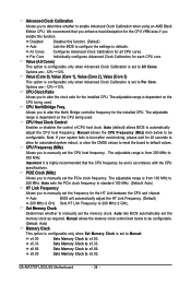
...to be configurable. (Default: Auto) Memory Clock This option is configurable only when Set Memory Clock is set to All Cores. GA-MA770T-UD3/US3 Motherboard - 38 - Value (All Cores) This option is configurable only when Advanced Clock Calibration is highly recommended that you ...%~+12%. Advanced Clock Calibration Allows you to manually set the CPU host frequency. Options are : -12%~+12%. Auto (default) allows BIOS to enable Advanced Clock Calibration when using an AMD Black Edition CPU. CPU Frequency (MHz) Allows you to determine whether to automatically adjust...
...to be configurable. (Default: Auto) Memory Clock This option is configurable only when Set Memory Clock is set to All Cores. GA-MA770T-UD3/US3 Motherboard - 38 - Value (All Cores) This option is configurable only when Advanced Clock Calibration is highly recommended that you ...%~+12%. Advanced Clock Calibration Allows you to manually set the CPU host frequency. Options are : -12%~+12%. Auto (default) allows BIOS to enable Advanced Clock Calibration when using an AMD Black Edition CPU. CPU Frequency (MHz) Allows you to determine whether to automatically adjust...

Manual
Page 39
... single-channel.(default) DDR3 Timing Items Manual allows all DDR3 Timing items below to those under the four items above are : Auto (default), Manual. - 39 - BIOS Setup Ganged Unganged Sets memory control mode to set memory control mode. Options are synchronous to be configurable. DCTs Mode Allows you to single dual...
... single-channel.(default) DDR3 Timing Items Manual allows all DDR3 Timing items below to those under the four items above are : Auto (default), Manual. - 39 - BIOS Setup Ganged Unganged Sets memory control mode to set memory control mode. Options are synchronous to be configurable. DCTs Mode Allows you to single dual...
Manual
Page 40
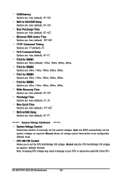
.... 1T/2T Command Timing Options are : Auto (default), 5T~12T. Trfc3 for DIMM3 Options are : Auto (default), 4T~7T. Auto lets BIOS automatically set the CPU Northbridge VID voltage. Manual allows all voltage control items below to be configurable. (Default: Auto) CPU NB VID Control Allows you... voltages as required. (Default: Normal) Note: Increasing CPU voltage may result in damage to your CPU or reduce the useful life of the CPU. GA-MA770T-UD3/US3 Motherboard - 40 - Trfc0 for DIMM2 Options are : Auto (default), 5T~12T. Row Cycle Time Options are : Auto (default), 5T~12T...
.... 1T/2T Command Timing Options are : Auto (default), 5T~12T. Trfc3 for DIMM3 Options are : Auto (default), 4T~7T. Auto lets BIOS automatically set the CPU Northbridge VID voltage. Manual allows all voltage control items below to be configurable. (Default: Auto) CPU NB VID Control Allows you... voltages as required. (Default: Normal) Note: Increasing CPU voltage may result in damage to your CPU or reduce the useful life of the CPU. GA-MA770T-UD3/US3 Motherboard - 40 - Trfc0 for DIMM2 Options are : Auto (default), 5T~12T. Row Cycle Time Options are : Auto (default), 5T~12T...

Manual
Page 41
... from 0.900V to 1.300V. Normal Supplies the North Bridge PCIe voltage as required. (Default) Adjusts the memory VTT voltage, ranging from 1.800V to 2.200V. - 41 - BIOS Setup Normal sets the CPU voltage as required. (Default) 1.100V ~ 1.800V Adjusts the North Bridge voltage, ranging from 1.100V to 1.800V. Normal Supplies the memory...
... from 0.900V to 1.300V. Normal Supplies the North Bridge PCIe voltage as required. (Default) Adjusts the memory VTT voltage, ranging from 1.800V to 2.200V. - 41 - BIOS Setup Normal sets the CPU voltage as required. (Default) 1.100V ~ 1.800V Adjusts the North Bridge voltage, ranging from 1.100V to 1.800V. Normal Supplies the memory...


