
Manual
Page 23
...design. The types of a CPU fan with fan speed control design. The motherboard supports CPU fan speed control, which requires the use of floppy disk drives ... a jumper cap on the headers. 6) FDD (Floppy Disk Drive Connector) This connector is the ground wire). Before connecting a floppy disk drive, be sure to locate pin 1 of different color. 33 1... to prevent your CPU and system from overheating. Hardware Installation When connecting a fan cable, be installed inside the chassis. 1 CPU_FAN CPU_FAN: Pin No. 1 2 3 4 Definition GND +12V / Speed Control Sense Speed Control ...
...design. The types of a CPU fan with fan speed control design. The motherboard supports CPU fan speed control, which requires the use of floppy disk drives ... a jumper cap on the headers. 6) FDD (Floppy Disk Drive Connector) This connector is the ground wire). Before connecting a floppy disk drive, be sure to locate pin 1 of different color. 33 1... to prevent your CPU and system from overheating. Hardware Installation When connecting a fan cable, be installed inside the chassis. 1 CPU_FAN CPU_FAN: Pin No. 1 2 3 4 Definition GND +12V / Speed Control Sense Speed Control ...
Manual
Page 26
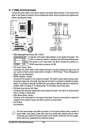
... (Front Panel Header) Connect the power switch, reset switch, speaker and system status indicator on the chassis front panel to this header, make sure the wire assignments and the pin assignments are matched correctly. Message/Power/ Power Sleep LED Switch Speaker MSG+ MSG... the chassis front panel. When connecting your system using the power switch (refer to Chapter 2, "BIOS Setup," "Power Management Setup," for information about beep codes. • HD (Hard Drive Activity LED, Blue) Connects to the power status indicator on the chassis front panel. GA-MA770T-UD3/US3 Motherboard - ...
... (Front Panel Header) Connect the power switch, reset switch, speaker and system status indicator on the chassis front panel to this header, make sure the wire assignments and the pin assignments are matched correctly. Message/Power/ Power Sleep LED Switch Speaker MSG+ MSG... the chassis front panel. When connecting your system using the power switch (refer to Chapter 2, "BIOS Setup," "Power Management Setup," for information about beep codes. • HD (Hard Drive Activity LED, Blue) Connects to the power status indicator on the chassis front panel. GA-MA770T-UD3/US3 Motherboard - ...

Manual
Page 27
... audio (only supported when using an HD front panel audio module), refer to this header. Make sure the wire assignments of the module connector match the pin assignments of the motherboard header. Pin No. Definition 1 CD-L 2 GND 1 3 GND 4 CD-R - 27 - Hardware Installation...You may connect the audio cable that came with your chassis front panel audio module to Chapter 5, "Configuring 2/4/5.1/7.1-Channel Audio." • Some chassis provide a front panel audio module that has different wire assignments, please contact the chassis manufacturer. 13) CD_IN (CD In Connector) You may...
... audio (only supported when using an HD front panel audio module), refer to this header. Make sure the wire assignments of the module connector match the pin assignments of the motherboard header. Pin No. Definition 1 CD-L 2 GND 1 3 GND 4 CD-R - 27 - Hardware Installation...You may connect the audio cable that came with your chassis front panel audio module to Chapter 5, "Configuring 2/4/5.1/7.1-Channel Audio." • Some chassis provide a front panel audio module that has different wire assignments, please contact the chassis manufacturer. 13) CD_IN (CD In Connector) You may...


