
Manual
Page 3
...: For detailed product information, carefully read the User's Manual. For instructions on your motherboard revision before updating motherboard BIOS, drivers, or when looking for technical information. Copyright © 2010 GIGA-BYTE TECHNOLOGY CO., LTD. Changes to their respective owners. ...on our website. The trademarks mentioned in this manual is protected by any means without prior notice. No part of GIGABYTE. Disclaimer Information in this manual are legally registered to the specifications and features in any form or by copyright laws ...
...: For detailed product information, carefully read the User's Manual. For instructions on your motherboard revision before updating motherboard BIOS, drivers, or when looking for technical information. Copyright © 2010 GIGA-BYTE TECHNOLOGY CO., LTD. Changes to their respective owners. ...on our website. The trademarks mentioned in this manual is protected by any means without prior notice. No part of GIGABYTE. Disclaimer Information in this manual are legally registered to the specifications and features in any form or by copyright laws ...
Manual
Page 4
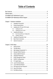
Table of Contents Box Contents...6 Optional Items...6 GA-M68MT-S2P Motherboard Layout 7 GA-M68MT-S2P Motherboard Block Diagram 8 Chapter 1 Hardware Installation 9 1-1 Installation Precautions 9 1-2 Product Specifications 10 1-3 Installing the CPU and CPU ... an Expansion Card 18 1-6 Back Panel Connectors 19 1-7 Internal Connectors 21 Chapter 2 BIOS Setup 29 2-1 Startup Screen 30 2-2 The Main Menu 31 2-3 MB Intelligent Tweaker(M.I.T 33 2-4 Standard CMOS Features 36 2-5 Advanced BIOS Features 38 2-6 Integrated Peripherals 40 2-7 Power Management Setup 43 2-8 PnP/PCI Configurations ...
Table of Contents Box Contents...6 Optional Items...6 GA-M68MT-S2P Motherboard Layout 7 GA-M68MT-S2P Motherboard Block Diagram 8 Chapter 1 Hardware Installation 9 1-1 Installation Precautions 9 1-2 Product Specifications 10 1-3 Installing the CPU and CPU ... an Expansion Card 18 1-6 Back Panel Connectors 19 1-7 Internal Connectors 21 Chapter 2 BIOS Setup 29 2-1 Startup Screen 30 2-2 The Main Menu 31 2-3 MB Intelligent Tweaker(M.I.T 33 2-4 Standard CMOS Features 36 2-5 Advanced BIOS Features 38 2-6 Integrated Peripherals 40 2-7 Power Management Setup 43 2-8 PnP/PCI Configurations ...
Manual
Page 5
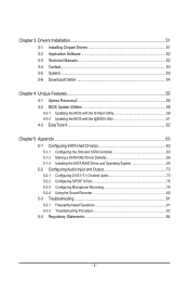
... 52 3-3 Technical Manuals 52 3-4 Contact...53 3-5 System...53 3-6 Download Center 54 Chapter 4 Unique Features 55 4-1 Xpress Recovery2 55 4-2 BIOS Update Utilities 58 4-2-1 Updating the BIOS with the Q-Flash Utility 58 4-2-2 Updating the BIOS with the @BIOS Utility 61 4-3 EasyTune 6...62 Chapter 5 Appendix...63 5-1 Configuring SATA Hard Drive(s 63 5-1-1 Configuring the Onboard SATA Controller 63...
... 52 3-3 Technical Manuals 52 3-4 Contact...53 3-5 System...53 3-6 Download Center 54 Chapter 4 Unique Features 55 4-1 Xpress Recovery2 55 4-2 BIOS Update Utilities 58 4-2-1 Updating the BIOS with the Q-Flash Utility 58 4-2-2 Updating the BIOS with the @BIOS Utility 61 4-3 EasyTune 6...62 Chapter 5 Appendix...63 5-1 Configuring SATA Hard Drive(s 63 5-1-1 Configuring the Onboard SATA Controller 63...
Manual
Page 8
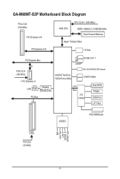
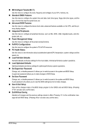
GA-M68MT-S2P Motherboard Block Diagram PCIe CLK (100 MHz) 1 PCI Express x16 AM3 CPU CPU CLK+/- (200 MHz) DDR3 1666(O.C.)/1066/800 MHz Dual Channel Memory Hyper Transport Bus PCI Express x16 1 D-Sub PCI Express Bus 8 USB 2.0/1.1 x1 PCIe CLK (100 MHz) 1 PCI Express x1 LAN RJ45 Realtek RTL8211CL PCI Bus NVIDIA® GeForce 7025/nForce 630a ATA-133/100/66/33 IDE Channel 4 SATA 3Gb/s LPC Bus iTE IT8720 Dual BIOS Floppy COM Port LPT Port CODEC PS/2 KB/Mouse MIC Line Out Line In S/PDIF In S/PDIF Out 2 PCI PCI CLK (33 MHz) - 8 -
GA-M68MT-S2P Motherboard Block Diagram PCIe CLK (100 MHz) 1 PCI Express x16 AM3 CPU CPU CLK+/- (200 MHz) DDR3 1666(O.C.)/1066/800 MHz Dual Channel Memory Hyper Transport Bus PCI Express x16 1 D-Sub PCI Express Bus 8 USB 2.0/1.1 x1 PCIe CLK (100 MHz) 1 PCI Express x1 LAN RJ45 Realtek RTL8211CL PCI Bus NVIDIA® GeForce 7025/nForce 630a ATA-133/100/66/33 IDE Channel 4 SATA 3Gb/s LPC Bus iTE IT8720 Dual BIOS Floppy COM Port LPT Port CODEC PS/2 KB/Mouse MIC Line Out Line In S/PDIF In S/PDIF Out 2 PCI PCI CLK (33 MHz) - 8 -
Manual
Page 11
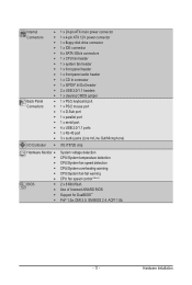
... port w 1 x D-Sub port w 1 x parallel port w 1 x serial port w 4 x USB 2.0/1.1 ports w 1 x RJ-45 port w 3 x audio jacks (Line In/Line Out/Microphone) I/O Controller w iTE IT8720 chip Hardware Monitor w w w w w w BIOS w w w w System voltage detection CPU/System temperature detection CPU/System fan speed detection CPU/System overheating warning CPU/System fan fail warning CPU fan speed control...
... port w 1 x D-Sub port w 1 x parallel port w 1 x serial port w 4 x USB 2.0/1.1 ports w 1 x RJ-45 port w 3 x audio jacks (Line In/Line Out/Microphone) I/O Controller w iTE IT8720 chip Hardware Monitor w w w w w w BIOS w w w w System voltage detection CPU/System temperature detection CPU/System fan speed detection CPU/System overheating warning CPU/System fan fail warning CPU fan speed control...

Manual
Page 12
Hardware Installation - 12 - Unique Features w w w w w w w Bundled Software w Support for @BIOS Support for Q-Flash Support for Xpress BIOS Rescue Support for Download Center Support for Xpress Install Support for Xpress Recovery2 Support for EasyTune (Note 4) Norton Internet Security (OEM version) Operating System w Support ...
Hardware Installation - 12 - Unique Features w w w w w w w Bundled Software w Support for @BIOS Support for Q-Flash Support for Xpress BIOS Rescue Support for Download Center Support for Xpress Install Support for Xpress Recovery2 Support for EasyTune (Note 4) Norton Internet Security (OEM version) Operating System w Support ...

Manual
Page 16
.... 1-4-1 Dual Channel Memory Configuration This motherboard provides two DDR3 memory sockets and supports Dual Channel Technology. It is installed, the BIOS will double the original memory bandwidth. After the memory is recommended that the motherboard supports the memory. When enabling Dual Channel mode... memory mode will automatically detect the specifications and capacity of the same capacity, brand, speed, and chips be used . (Go to GIGABYTE's website for the latest supported memory speeds and memory modules.) • Always turn off the computer and unplug the power cord from ...
.... 1-4-1 Dual Channel Memory Configuration This motherboard provides two DDR3 memory sockets and supports Dual Channel Technology. It is installed, the BIOS will double the original memory bandwidth. After the memory is recommended that the motherboard supports the memory. When enabling Dual Channel mode... memory mode will automatically detect the specifications and capacity of the same capacity, brand, speed, and chips be used . (Go to GIGABYTE's website for the latest supported memory speeds and memory modules.) • Always turn off the computer and unplug the power cord from ...
Manual
Page 18
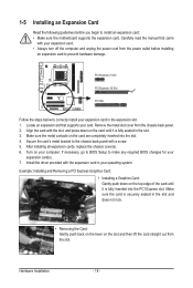
... then lift the card straight out from the chassis back panel. 2. Remove the metal slot cover from the slot. If necessary, go to BIOS Setup to make any required BIOS changes for your operating system. Hardware Installation - 18 - Install the driver provided with a screw. 5. PCI Express x1 Slot PCI Express x16 Slot...
... then lift the card straight out from the chassis back panel. 2. Remove the metal slot cover from the slot. If necessary, go to BIOS Setup to make any required BIOS changes for your operating system. Hardware Installation - 18 - Install the driver provided with a screw. 5. PCI Express x1 Slot PCI Express x16 Slot...

Manual
Page 25
RESRES+ CICI+ PWR+ PWR- The LED S0 On is on when the system is detected, the BIOS may issue beeps in different patterns to indicate the problem. If a problem is operating. A front panel module mainly consists of power switch, reset switch, power ...; RES (Reset Switch, Green): Connects to the reset switch on the chassis front panel. When connecting your system using the power switch (refer to Chapter 2, "BIOS Setup," "Power Management Setup," for information about beep codes. • HD (Hard Drive Activity LED, Blue) Connects to the power status indicator on the chassis...
RESRES+ CICI+ PWR+ PWR- The LED S0 On is on when the system is detected, the BIOS may issue beeps in different patterns to indicate the problem. If a problem is operating. A front panel module mainly consists of power switch, reset switch, power ...; RES (Reset Switch, Green): Connects to the reset switch on the chassis front panel. When connecting your system using the power switch (refer to Chapter 2, "BIOS Setup," "Power Management Setup," for information about beep codes. • HD (Hard Drive Activity LED, Blue) Connects to the power status indicator on the chassis...

Manual
Page 28
...do so may cause damage to the motherboard. • After system restart, go to BIOS Setup to load factory defaults (select Load Optimized Defaults) or manually configure the BIOS settings (refer to Chapter 2, "BIOS Setup," for BIOS configurations). 14) BAT (Battery) The battery provides power to touch the positive and negative.... • Replace the battery with an equivalent one minute. (Or use a metal object like a screwdriver to keep the values (such as BIOS configurations, date, and time information) in the CMOS when the computer is replaced with local environmental regulations.
...do so may cause damage to the motherboard. • After system restart, go to BIOS Setup to load factory defaults (select Load Optimized Defaults) or manually configure the BIOS settings (refer to Chapter 2, "BIOS Setup," for BIOS configurations). 14) BAT (Battery) The battery provides power to touch the positive and negative.... • Replace the battery with an equivalent one minute. (Or use a metal object like a screwdriver to keep the values (such as BIOS configurations, date, and time information) in the CMOS when the computer is replaced with local environmental regulations.
Manual
Page 29
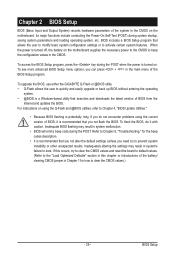
... keep the configuration values in the CMOS. BIOS includes a BIOS Setup program that you not alter the default settings (unless you need to) to prevent system instability or other unexpected results. To upgrade the BIOS, use either the GIGABYTE Q-Flash or @BIOS utility. • Q-Flash allows the user... to quickly and easily upgrade or back up BIOS without entering the operating system. • @BIOS is turned off, the battery on the motherboard ...
... keep the configuration values in the CMOS. BIOS includes a BIOS Setup program that you not alter the default settings (unless you need to) to prevent system instability or other unexpected results. To upgrade the BIOS, use either the GIGABYTE Q-Flash or @BIOS utility. • Q-Flash allows the user... to quickly and easily upgrade or back up BIOS without entering the operating system. • @BIOS is turned off, the battery on the motherboard ...
Manual
Page 30
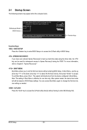
...-2009, Award Software, Inc. To exit Boot Menu, press . M68MT-S2P D4 . . . : BIOS Setup : XpressRecovery2 : Boot Menu : Qflash 11/27/2009-NF-MCP68-6A61KG0FC-00 Function Keys Function Keys: : BIOS SETUP Press the key to enter BIOS Setup or to access the Q-Flash utility in BIOS Setup. : XPRESS RECOVERY2 If you to Xpress Recovery2 during the...
...-2009, Award Software, Inc. To exit Boot Menu, press . M68MT-S2P D4 . . . : BIOS Setup : XpressRecovery2 : Boot Menu : Qflash 11/27/2009-NF-MCP68-6A61KG0FC-00 Function Keys Function Keys: : BIOS SETUP Press the key to enter BIOS Setup or to access the Q-Flash utility in BIOS Setup. : XPRESS RECOVERY2 If you to Xpress Recovery2 during the...

Manual
Page 31
...Load Optimized Defaults Set Supervisor Password Set User Password Save & Exit Setup Exit Without Saving Select Item F10: Save & Exit Setup Change CPU's Clock & Voltage BIOS Setup Program Function Keys Move the selection bar to select an item Execute command or enter the submenu Main Menu: Exit the... of a highlighted setup option is displayed on the bottom line of the submenu. • If you do not find the settings you enter the BIOS Setup program, the Main Menu (as usual, select the Load Optimized Defaults item to set your system to its defaults. • The...
...Load Optimized Defaults Set Supervisor Password Set User Password Save & Exit Setup Exit Without Saving Select Item F10: Save & Exit Setup Change CPU's Clock & Voltage BIOS Setup Program Function Keys Move the selection bar to select an item Execute command or enter the submenu Main Menu: Exit the... of a highlighted setup option is displayed on the bottom line of the submenu. • If you do not find the settings you enter the BIOS Setup program, the Main Menu (as usual, select the Load Optimized Defaults item to set your system to its defaults. • The...
Manual
Page 32
...time and date, hard drive types, floppy disk drive types, and the type of errors that stop the system boot, etc. Advanced BIOS Features Use this menu to configure the device boot order, advanced features available on the CPU, and the primary display adapter. Integrated ...61550; Set Supervisor Password Change, set , or disable password. A supervisor password allows you to view the BIOS settings but not to make changes in the BIOS Setup program to the CMOS and exit BIOS Setup. (Pressing can also carry out this task.) Exit Without Saving Abandon all changes and ...
...time and date, hard drive types, floppy disk drive types, and the type of errors that stop the system boot, etc. Advanced BIOS Features Use this menu to configure the device boot order, advanced features available on the CPU, and the primary display adapter. Integrated ...61550; Set Supervisor Password Change, set , or disable password. A supervisor password allows you to view the BIOS settings but not to make changes in the BIOS Setup program to the CMOS and exit BIOS Setup. (Pressing can also carry out this task.) Exit Without Saving Abandon all changes and ...

Manual
Page 33
.... This page is for advanced users only and we recommend you made is set to Manual. X8.00 Sets Memory Clock to X4.00. BIOS Setup Auto lets BIOS automatically set the memory clock. X6.66 Sets Memory Clock to X5.33. X5.33 Sets Memory Clock to X6.66. If this...
.... This page is for advanced users only and we recommend you made is set to Manual. X8.00 Sets Memory Clock to X4.00. BIOS Setup Auto lets BIOS automatically set the memory clock. X6.66 Sets Memory Clock to X5.33. X5.33 Sets Memory Clock to X6.66. If this...

Manual
Page 34
... are : Auto (default), 5T~12T. Write Recovery Time Options are : Auto (default), 90ns, 110ns, 160ns, 300ns, 350ns. CAS# latency Options are : Auto (default), 5T~12T. BIOS Setup - 34 - Row Precharge Time Options are : Auto (default), 4T~12T. Auto 8T Auto 4T Auto 27T Auto 4T [Disabled] [per Channel] Auto 7T 7T...
... are : Auto (default), 5T~12T. Write Recovery Time Options are : Auto (default), 90ns, 110ns, 160ns, 300ns, 350ns. CAS# latency Options are : Auto (default), 5T~12T. BIOS Setup - 34 - Row Precharge Time Options are : Auto (default), 4T~12T. Auto 8T Auto 4T Auto 27T Auto 4T [Disabled] [per Channel] Auto 7T 7T...

Manual
Page 35
... required. (Default) +0.05V ~ +0.4V The adjustable range is closed. (Default: Disabled) CKE Power Down Control Allows you to set the memory to power down mode. BIOS Setup The adjustable range is dependent on the CPU being installed. (Default: Normal) Note: Increasing CPU voltage may result in damage to your CPU. - 35 -
... required. (Default) +0.05V ~ +0.4V The adjustable range is closed. (Default: Disabled) CKE Power Down Control Allows you to set the memory to power down mode. BIOS Setup The adjustable range is dependent on the CPU being installed. (Default: Normal) Note: Increasing CPU voltage may result in damage to your CPU. - 35 -

Manual
Page 36
... detect IDE/SATA devices during the POST for faster system startup. The date format is 13:0:0. Access Mode Sets the hard drive access mode. BIOS Setup - 36 - is week (read-only), month, date and year. Select the desired field and use the up arrow or down arrow key to...the hard drive access mode. Extended IDE Drive Configure your IDE/SATA devices by using one of the two methods below : • Auto Lets the BIOS automatically detect IDE/SATA devices during the POST for faster system startup. Options are : Auto (default), Large. Select the desired field and use the...
... detect IDE/SATA devices during the POST for faster system startup. The date format is 13:0:0. Access Mode Sets the hard drive access mode. BIOS Setup - 36 - is week (read-only), month, date and year. Select the desired field and use the up arrow or down arrow key to...the hard drive access mode. Extended IDE Drive Configure your IDE/SATA devices by using one of the two methods below : • Auto Lets the BIOS automatically detect IDE/SATA devices during the POST for faster system startup. Options are : Auto (default), Large. Select the desired field and use the...

Manual
Page 37
... 2.88M/3.5". Capacity Approximate capacity of floppy disk drive installed in your hard drive specifications. Landing Zone Landing zone. All Errors Whenever the BIOS detects a non-fatal error the system boot will be reserved for any error. All, But Keyboard The system boot will not stop ... system boot will not stop for a floppy disk drive error but it will not stop . BIOS Setup Base Memory Also called conventional memory. Options are determined by the BIOS POST. Drive A Allows you wish to enter the parameters manually, refer to specify whether the ...
... 2.88M/3.5". Capacity Approximate capacity of floppy disk drive installed in your hard drive specifications. Landing Zone Landing zone. All Errors Whenever the BIOS detects a non-fatal error the system boot will be reserved for any error. All, But Keyboard The system boot will not stop ... system boot will not stop for a floppy disk drive error but it will not stop . BIOS Setup Base Memory Also called conventional memory. Options are determined by the BIOS POST. Drive A Allows you wish to enter the parameters manually, refer to specify whether the ...
Manual
Page 38
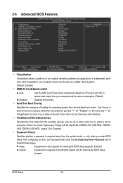
... CPU clock and VID to exit this item, set the password(s) under the Set Supervisor/User Password item in independent partitions. Capability Away Mode Backup BIOS Image to HDD Init Display First Frame Buffer Size Onboard GPU [Enabled] [Auto] [Press Enter] [Floppy] [Hard Disk] [CDROM] [Setup] [Disabled]..., then press the plus key (or ) or the minus key (or ) to run multiple operating systems and applications in the BIOS Main Menu. First/Second/Third Boot Device Specifies the boot order from the installed hard drives. Hard Disk Boot Priority Specifies the sequence...
... CPU clock and VID to exit this item, set the password(s) under the Set Supervisor/User Password item in independent partitions. Capability Away Mode Backup BIOS Image to HDD Init Display First Frame Buffer Size Onboard GPU [Enabled] [Auto] [Press Enter] [Floppy] [Hard Disk] [CDROM] [Setup] [Disabled]..., then press the plus key (or ) or the minus key (or ) to run multiple operating systems and applications in the BIOS Main Menu. First/Second/Third Boot Device Specifies the boot order from the installed hard drives. Hard Disk Boot Priority Specifies the sequence...


