Manual
Page 4
Table of Contents ItemChecklist ...6 OptionalAccessories ...6 GA-M61PM-S2 (rev. 2.0) Motherboard Layout 7 Block Diagram ...8 Chapter 1 Hardware Installation 9 1-1 Considerations Prior to Installation 9 1-2 Feature Summary 10 1-3 Installation of ... 1-5 Installation of Expansion Cards 16 1-6 I/O Back Panel Introduction 17 1-7 Connectors Introduction 18 Chapter 2 BIOS Setup 29 The Main Menu (For example: BIOS Ver. : F4d 30 2-1 Standard CMOS Features 32 2-2 Advanced BIOS Features 34 2-3 IntegratedPeripherals 36 2-4 Power Management Setup 40 2-5 PnP/PCI Configurations 41 2-6 PC Health ...
Table of Contents ItemChecklist ...6 OptionalAccessories ...6 GA-M61PM-S2 (rev. 2.0) Motherboard Layout 7 Block Diagram ...8 Chapter 1 Hardware Installation 9 1-1 Considerations Prior to Installation 9 1-2 Feature Summary 10 1-3 Installation of ... 1-5 Installation of Expansion Cards 16 1-6 I/O Back Panel Introduction 17 1-7 Connectors Introduction 18 Chapter 2 BIOS Setup 29 The Main Menu (For example: BIOS Ver. : F4d 30 2-1 Standard CMOS Features 32 2-2 Advanced BIOS Features 34 2-3 IntegratedPeripherals 36 2-4 Power Management Setup 40 2-5 PnP/PCI Configurations 41 2-6 PC Health ...
Manual
Page 5
Chapter 3 Drivers Installation 47 3-1 Install Chipset Drivers 47 3-2 SoftwareApplications 48 3-3 Driver CD Information 48 3-4 Hardware Information 49 3-5 Contact Us ...49 Chapter 4 Appendix 51 4-1 Unique Software Utilities 51 4-1-1 EasyTune 5 Introduction 51 4-1-2 Xpress Recovery2 Introduction 52 4-1-3 Flash BIOS Method Introduction 54 4-1-4 Configuring SATA Hard Drive(s 58 4-1-5 2- / 4- / 6- / 8- Channel Audio Function Introduction 68 4-2 Troubleshooting 73 - 5 -
Chapter 3 Drivers Installation 47 3-1 Install Chipset Drivers 47 3-2 SoftwareApplications 48 3-3 Driver CD Information 48 3-4 Hardware Information 49 3-5 Contact Us ...49 Chapter 4 Appendix 51 4-1 Unique Software Utilities 51 4-1-1 EasyTune 5 Introduction 51 4-1-2 Xpress Recovery2 Introduction 52 4-1-3 Flash BIOS Method Introduction 54 4-1-4 Configuring SATA Hard Drive(s 58 4-1-5 2- / 4- / 6- / 8- Channel Audio Function Introduction 68 4-2 Troubleshooting 73 - 5 -
Manual
Page 7
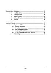
GA-M61PM-S2 (rev. 2.0) Motherboard Layout VGA COMA LPT USB USB 1394 LAN KB_MS ATX_12V Socket AM2 ATX CPU_FAN IT8716 AUDIO F_AUDIO BIOS CI PCIE_16 GA-M61PM-S2 RTL8211 PCIE_1 PCI1 CD_IN PCI2 CODEC REV: 2.0 SPDIF_IO COMB CLR_CMOS BATTERY nVIDIA® GeForce 6100/ nForce 430 TSB43AB23 F1_1394 F2_1394 SYS_FAN IDE FDD F_USB2 F_USB1 F_USB3 F_PANEL PWR_LED DDRII_1 DDRII_2 DDRII_3 DDRII_4 SATAII1 SATAII3 SATAII0 SATAII2 - 7 -
GA-M61PM-S2 (rev. 2.0) Motherboard Layout VGA COMA LPT USB USB 1394 LAN KB_MS ATX_12V Socket AM2 ATX CPU_FAN IT8716 AUDIO F_AUDIO BIOS CI PCIE_16 GA-M61PM-S2 RTL8211 PCIE_1 PCI1 CD_IN PCI2 CODEC REV: 2.0 SPDIF_IO COMB CLR_CMOS BATTERY nVIDIA® GeForce 6100/ nForce 430 TSB43AB23 F1_1394 F2_1394 SYS_FAN IDE FDD F_USB2 F_USB1 F_USB3 F_PANEL PWR_LED DDRII_1 DDRII_2 DDRII_3 DDRII_4 SATAII1 SATAII3 SATAII0 SATAII2 - 7 -

Manual
Page 8
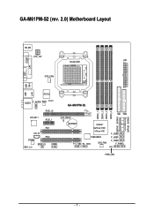
Block Diagram PCIe CLK (100 MHz) VGA AMD Socket AM2 CPU CPU CLK+/-(200 MHz) DDRII 800/667/533/400 MHz DIMM Dual Channel Memory Hyper Transport Bus PCI Express x16 LAN RJ45 PCI Express x1 Bus x1 PCIe CLK (100 MHz) 1 PCI Express x1 RTL8211 PCI Bus TSB43AB23 4 SATA 3Gb/s nVIDIA® GeForce 6100/ nForce 430 LPC BUS ATA 33/66/100/133 IDE Channel BIOS Floppy IT8716 LPT Port COM Ports PS/2 Keyboard/ Mouse CODEC 3 IEEE 1394a Surround Speaker Out Center/Subwoofer Spear Out Side Speaker Out MIC Line-Out Line-In SPDIF In SPDIF Out 2 PCI PCI CLK (33 MHz) 10 USB Ports - 8 -
Block Diagram PCIe CLK (100 MHz) VGA AMD Socket AM2 CPU CPU CLK+/-(200 MHz) DDRII 800/667/533/400 MHz DIMM Dual Channel Memory Hyper Transport Bus PCI Express x16 LAN RJ45 PCI Express x1 Bus x1 PCIe CLK (100 MHz) 1 PCI Express x1 RTL8211 PCI Bus TSB43AB23 4 SATA 3Gb/s nVIDIA® GeForce 6100/ nForce 430 LPC BUS ATA 33/66/100/133 IDE Channel BIOS Floppy IT8716 LPT Port COM Ports PS/2 Keyboard/ Mouse CODEC 3 IEEE 1394a Surround Speaker Out Center/Subwoofer Spear Out Side Speaker Out MIC Line-Out Line-In SPDIF In SPDIF Out 2 PCI PCI CLK (33 MHz) 10 USB Ports - 8 -

Manual
Page 11
...Š CPU / System fan failure warning Š Supports CPU Smart Fan function(Note 2) BIOS Š 1 4 Mbit flash ROM Š Use of licensed AWARD BIOS Additional Features Š Supports @BIOS Š Supports Download Center Š Supports Q-Flash Š Supports EasyTune (only supports Hardware... Monitor function)(Note 3) Š Supports Xpress Install Š Supports Xpress Recovery2 Š Supports Xpress BIOS Rescue Bundle Software Š Norton Internet Security (OEM version) Form Factor Š Micro ATX form factor; 24.4cm x 24.4cm...
...Š CPU / System fan failure warning Š Supports CPU Smart Fan function(Note 2) BIOS Š 1 4 Mbit flash ROM Š Use of licensed AWARD BIOS Additional Features Š Supports @BIOS Š Supports Download Center Š Supports Q-Flash Š Supports EasyTune (only supports Hardware... Monitor function)(Note 3) Š Supports Xpress Install Š Supports Xpress Recovery2 Š Supports Xpress BIOS Rescue Bundle Software Š Norton Internet Security (OEM version) Form Factor Š Micro ATX form factor; 24.4cm x 24.4cm...

Manual
Page 14
If you wish to lock the DIMM module. The motherboard supports DDRII memory modules, whereby BIOS will automatically detect memory capacity and specifications. Then push it down. Fig.2 Close the plastic clip at both edges of the DIMM sockets to remove ..., so the DIMM memory module can be installed in one direction. English 1-4 Installation of Memory Before installing the memory modules, please comply with each slot. GA-M61PM-S2 (rev. 2.0) Motherboard - 14 -
If you wish to lock the DIMM module. The motherboard supports DDRII memory modules, whereby BIOS will automatically detect memory capacity and specifications. Then push it down. Fig.2 Close the plastic clip at both edges of the DIMM sockets to remove ..., so the DIMM memory module can be installed in one direction. English 1-4 Installation of Memory Before installing the memory modules, please comply with each slot. GA-M61PM-S2 (rev. 2.0) Motherboard - 14 -

Manual
Page 16
Read the related expansion card's instruction document before install the expansion card into expansion slot in the slot. 5. Install related driver from BIOS. 8. Make sure your computer's chassis cover. 7. Be sure the metal contacts on the card are indeed seated in motherboard. 4. Replace ... the steps outlined below: 1. Power on the slot. Remove your expansion card by the latch at the end of the PCI Express x16 slot. GA-M61PM-S2 (rev. 2.0) Motherboard - 16 - Press the expansion card firmly into the computer. 2. Replace the screw to release the card. When you try...
Read the related expansion card's instruction document before install the expansion card into expansion slot in the slot. 5. Install related driver from BIOS. 8. Make sure your computer's chassis cover. 7. Be sure the metal contacts on the card are indeed seated in motherboard. 4. Replace ... the steps outlined below: 1. Power on the slot. Remove your expansion card by the latch at the end of the PCI Express x16 slot. GA-M61PM-S2 (rev. 2.0) Motherboard - 16 - Press the expansion card firmly into the computer. 2. Replace the screw to release the card. When you try...
Manual
Page 21
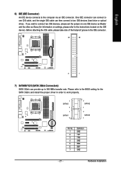
... devices (hard drive or optical drive). Hardware Installation English 6) IDE (IDE Connector) An IDE device connects to 300 MB/s transfer rate. Please refer to the BIOS setting for information on settings, please refer to the instructions located on one IDE cable, and the single IDE cable can connect to one IDE...
... devices (hard drive or optical drive). Hardware Installation English 6) IDE (IDE Connector) An IDE device connects to 300 MB/s transfer rate. Please refer to the BIOS setting for information on settings, please refer to the instructions located on one IDE cable, and the single IDE cable can connect to one IDE...
Manual
Page 27
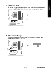
To clear CMOS, temporarily short the two pins. Pin No. Default doesn't include the jumper to detect if the chassis cover is removed. Open: Normal Short: Clear CMOS 17) CI (Chassis Intrusion, Case Open) This 2-pin connector allows your system to avoid improper use of this header. English 16) CLR_CMOS (Clear CMOS) You may clear the CMOS data to its default values by this header. Hardware Installation Definition 1 1 Signal 2 GND - 27 - You can check the "Case Open" status in BIOS Setup.
To clear CMOS, temporarily short the two pins. Pin No. Default doesn't include the jumper to detect if the chassis cover is removed. Open: Normal Short: Clear CMOS 17) CI (Chassis Intrusion, Case Open) This 2-pin connector allows your system to avoid improper use of this header. English 16) CLR_CMOS (Clear CMOS) You may clear the CMOS data to its default values by this header. Hardware Installation Definition 1 1 Signal 2 GND - 27 - You can check the "Case Open" status in BIOS Setup.

Manual
Page 29
... from CMOS, only for Option Page Setup Menu Load the fail-safe default CMOS value from the Internet. If you to a new BIOS, either Gigabyte's Q-Flash or @BIOS utility can enter the BIOS setup screen by pressing "Ctrl + F1". Quit and not save changes into CMOS Status Page Setup Menu and Option Page Setup...
... from CMOS, only for Option Page Setup Menu Load the fail-safe default CMOS value from the Internet. If you to a new BIOS, either Gigabyte's Q-Flash or @BIOS utility can enter the BIOS setup screen by pressing "Ctrl + F1". Quit and not save changes into CMOS Status Page Setup Menu and Option Page Setup...
Manual
Page 30
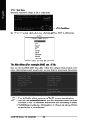
...GA-M61PM-S2 (rev. 2.0) Motherboard - 30 - English : Boot Menu Select boot sequence for onboard (or add-on the screen. Boot Menu == Select a Boot First device == Floppy LS120 Hard Disk CDROM ZIP USB-FDD USB-ZIP USB-CDROM USB-HDD Legacy LAN KL:Move Enter :Accept ESC:Exit The Main Menu (For example: BIOS...KLJI: Select Item F10: Save & Exit Setup Time, Date, Hard Disk Type... 1. Award Modular BIOS v6.00PG, An Energy Star Ally Copyright (C) 1984-2006, Award Software, Inc. M61PM-S2 F4d . . . . :BIOS Setup/Q-Flash, : Xpress Recovery2, : Boot Menu 11/22/2006-NV-MCP61-6A61KG02C-00 : Boot ...
...GA-M61PM-S2 (rev. 2.0) Motherboard - 30 - English : Boot Menu Select boot sequence for onboard (or add-on the screen. Boot Menu == Select a Boot First device == Floppy LS120 Hard Disk CDROM ZIP USB-FDD USB-ZIP USB-CDROM USB-HDD Legacy LAN KL:Move Enter :Accept ESC:Exit The Main Menu (For example: BIOS...KLJI: Select Item F10: Save & Exit Setup Time, Date, Hard Disk Type... 1. Award Modular BIOS v6.00PG, An Energy Star Ally Copyright (C) 1984-2006, Award Software, Inc. M61PM-S2 F4d . . . . :BIOS Setup/Q-Flash, : Xpress Recovery2, : Boot Menu 11/22/2006-NV-MCP61-6A61KG02C-00 : Boot ...

Manual
Page 31
... Setup Save CMOS value settings to Setup. „ Set User Password Change, set , or disable password. BIOS Setup English „ Standard CMOS Features This setup page includes all the items in standard compatible BIOS. „ Advanced BIOS Features This setup page includes all the items of Award special enhanced features. „ Integrated Peripherals...
... Setup Save CMOS value settings to Setup. „ Set User Password Change, set , or disable password. BIOS Setup English „ Standard CMOS Features This setup page includes all the items in standard compatible BIOS. „ Advanced BIOS Features This setup page includes all the items of Award special enhanced features. „ Integrated Peripherals...
Manual
Page 32
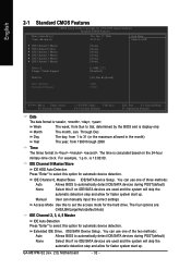
... , , , . IDE Channel 0, Master/Slave IDE/SATA Device Setup. Extended IDE Drive. You can use one of three methods: Auto Allows BIOS to 31 (or the maximum allowed in . GA-M61PM-S2 (rev. 2.0) Motherboard - 32 - English 2-1 Standard CMOS Features CMOS Setup Utility-Copyright (C) 1984-2006 Award Software Standard CMOS Features Date (mm:... skip the automatic detection step and allow for faster system start up . You can use one of the two methods: Auto Allows BIOS to Sat, determined by the BIOS and is 13:00:00. is display-only Month The month, Jan.
... , , , . IDE Channel 0, Master/Slave IDE/SATA Device Setup. Extended IDE Drive. You can use one of three methods: Auto Allows BIOS to 31 (or the maximum allowed in . GA-M61PM-S2 (rev. 2.0) Motherboard - 32 - English 2-1 Standard CMOS Features CMOS Setup Utility-Copyright (C) 1984-2006 Award Software Standard CMOS Features Date (mm:... skip the automatic detection step and allow for faster system start up . You can use one of the two methods: Auto Allows BIOS to Sat, determined by the BIOS and is 13:00:00. is display-only Month The month, Jan.

Manual
Page 33
... it will be prompted. The value of base (or conventional) memory installed in the CPU's memory address map. - 33 - Extended Memory The BIOS determines how much extended memory is Enabled). 720K, 3.5" 3.5 inch double-sided drive; 720K byte capacity . 1.44M, 3.5" 3.5 inch double-sided ...44M byte capacity. 2.88M, 3.5" 3.5 inch double-sided drive; 2.88M byte capacity. English Access Mode Use this information. BIOS Setup All Errors Whenever the BIOS detects a non-fatal error the system will stop for any error that has been installed in the computer. All, But...
... it will be prompted. The value of base (or conventional) memory installed in the CPU's memory address map. - 33 - Extended Memory The BIOS determines how much extended memory is Enabled). 720K, 3.5" 3.5 inch double-sided drive; 720K byte capacity . 1.44M, 3.5" 3.5 inch double-sided ...44M byte capacity. 2.88M, 3.5" 3.5 inch double-sided drive; 2.88M byte capacity. English Access Mode Use this information. BIOS Setup All Errors Whenever the BIOS detects a non-fatal error the system will stop for any error that has been installed in the computer. All, But...
Manual
Page 34
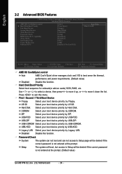
...Setup The system will boot, but access to Setup will be denied if the correct password is not entered at the prompt. (Default value) GA-M61PM-S2 (rev. 2.0) Motherboard - 34 - USB-CDROM Select your boot device priority by USB-CDROM. Disabled Disable this function. Press to move it... down the list. Select your boot device priority by Hard Disk. English 2-2 Advanced BIOS Features CMOS Setup Utility-Copyright (C) 1984-2006 Award Software Advanced BIOS Features AMD K8 Cool&Quiet control ` Hard Disk Boot Priority First Boot Device Second Boot Device Third ...
...Setup The system will boot, but access to Setup will be denied if the correct password is not entered at the prompt. (Default value) GA-M61PM-S2 (rev. 2.0) Motherboard - 34 - USB-CDROM Select your boot device priority by USB-CDROM. Disabled Disable this function. Press to move it... down the list. Select your boot device priority by Hard Disk. English 2-2 Advanced BIOS Features CMOS Setup Utility-Copyright (C) 1984-2006 Award Software Advanced BIOS Features AMD K8 Cool&Quiet control ` Hard Disk Boot Priority First Boot Device Second Boot Device Third ...

Manual
Page 35
...) Away Mode Disabled Disable this function. If you install a PCI card and a PCI Express VGA card on -chip frame buffer size to Always Enable. - 35 - BIOS Setup Disabled Disable HDD S.M.A.R.T. Enable If No Ext PEG Activate the onboard VGA first only when no PCI Express VGA card is installed. (Default value...
...) Away Mode Disabled Disable this function. If you install a PCI card and a PCI Express VGA card on -chip frame buffer size to Always Enable. - 35 - BIOS Setup Disabled Disable HDD S.M.A.R.T. Enable If No Ext PEG Activate the onboard VGA first only when no PCI Express VGA card is installed. (Default value...

Manual
Page 37
... Auto Auto detect Azalia audio function. (Default value) Disabled Disable Azalia audio function. NV SATA 2 Secondary RAID Enabled Enable RAID function for the system stability. BIOS Setup On-Chip MAC Lan Auto Auto-detect onboard LAN chip function. (Default value) Disabled Disable onboard LAN chip function. USB Memory Type SHADOW Set...
... Auto Auto detect Azalia audio function. (Default value) Disabled Disable Azalia audio function. NV SATA 2 Secondary RAID Enabled Enable RAID function for the system stability. BIOS Setup On-Chip MAC Lan Auto Auto-detect onboard LAN chip function. (Default value) Disabled Disable onboard LAN chip function. USB Memory Type SHADOW Set...
Manual
Page 39
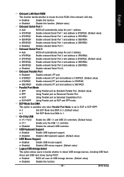
... Using Parallel port as ECP and EPP mode. ECP+EPP Using Parallel port as Enhanced Parallel Port. Disabled Disable the onboard USB controller. BIOS Setup Enabled Enable this function. On-Chip USB V1.1+V2.0 Enable the USB 1.1 and USB 2.0 controllers. (Default Value) V1.1 Enable... only the USB 1.1 controller. English Onboard LAN Boot ROM This function decide whether to 1. Onboard Serial Port 2 Auto BIOS will automatically setup the port 1 address. 3F8/IRQ4 Enable onboard Serial Port 1 and address is 3F8/IRQ4. (Default value) 2F8/IRQ3 Enable ...
... Using Parallel port as ECP and EPP mode. ECP+EPP Using Parallel port as Enhanced Parallel Port. Disabled Disable the onboard USB controller. BIOS Setup Enabled Enable this function. On-Chip USB V1.1+V2.0 Enable the USB 1.1 and USB 2.0 controllers. (Default Value) V1.1 Enable... only the USB 1.1 controller. English Onboard LAN Boot ROM This function decide whether to 1. Onboard Serial Port 2 Auto BIOS will automatically setup the port 1 address. 3F8/IRQ4 Enable onboard Serial Port 1 and address is 3F8/IRQ4. (Default value) 2F8/IRQ3 Enable ...

Manual
Page 41
...) Set IRQ 3,4,5,7,9,10,11,12,14,15 to power on the system. Enter Input password (from 1 to 5 characters to set the Keyboard Power On Password. BIOS Setup Password Enter from 1 to 5 characters) and press Enter to set the Keyboard Power On password. AC Back Function Soft-Off When AC-power back...
...) Set IRQ 3,4,5,7,9,10,11,12,14,15 to power on the system. Enter Input password (from 1 to 5 characters to set the Keyboard Power On Password. BIOS Setup Password Enter from 1 to 5 characters) and press Enter to set the Keyboard Power On password. AC Back Function Soft-Off When AC-power back...

Manual
Page 43
...fan power cable. 2-7 Load Fail-Safe Defaults CMOS Setup Utility-Copyright (C) 1984-2006 Award Software ` Standard CMOS Features ` Advanced BIOS Features ` Integrated Peripherals ` Power Management Setup ` PnP/PCI Configurations ` PC Health Status Load Fail-Safe Defaults Load Optimized Defaults ...minimum system performance. 2-8 Load Optimized Defaults CMOS Setup Utility-Copyright (C) 1984-2006 Award Software ` Standard CMOS Features ` Advanced BIOS Features ` Integrated Peripherals ` Power Management Setup ` PnP/PCI Configurations ` PC Health Status Load Fail-Safe Defaults Load Optimized ...
...fan power cable. 2-7 Load Fail-Safe Defaults CMOS Setup Utility-Copyright (C) 1984-2006 Award Software ` Standard CMOS Features ` Advanced BIOS Features ` Integrated Peripherals ` Power Management Setup ` PnP/PCI Configurations ` PC Health Status Load Fail-Safe Defaults Load Optimized Defaults ...minimum system performance. 2-8 Load Optimized Defaults CMOS Setup Utility-Copyright (C) 1984-2006 Award Software ` Standard CMOS Features ` Advanced BIOS Features ` Integrated Peripherals ` Power Management Setup ` PnP/PCI Configurations ` PC Health Status Load Fail-Safe Defaults Load Optimized ...


