Manual
Page 4
... the CPU and CPU Cooler 12 1-3-1 Installation of the CPU 12 1-3-2 Installation of the CPU Cooler 13 1-4 Installation of Memory 14 1-5 Installation of Expansion Cards 16 1-6 I/O Back Panel Introduction 17 1-7 Connectors Introduction 18 Chapter 2 BIOS Setup 29 The Main Menu (For example: BIOS Ver. : F4d 30 2-1 Standard CMOS Features 32 2-2 Advanced BIOS Features 34 2-3 IntegratedPeripherals 36 2-4 Power Management Setup 40 2-5 PnP/PCI Configurations 41 2-6 PC Health Status 42 2-7 Load Fail-Safe Defaults 43 2-8 Load Optimized Defaults 43 2-9 Set Supervisor/User Password...
... the CPU and CPU Cooler 12 1-3-1 Installation of the CPU 12 1-3-2 Installation of the CPU Cooler 13 1-4 Installation of Memory 14 1-5 Installation of Expansion Cards 16 1-6 I/O Back Panel Introduction 17 1-7 Connectors Introduction 18 Chapter 2 BIOS Setup 29 The Main Menu (For example: BIOS Ver. : F4d 30 2-1 Standard CMOS Features 32 2-2 Advanced BIOS Features 34 2-3 IntegratedPeripherals 36 2-4 Power Management Setup 40 2-5 PnP/PCI Configurations 41 2-6 PC Health Status 42 2-7 Load Fail-Safe Defaults 43 2-8 Load Optimized Defaults 43 2-9 Set Supervisor/User Password...

Manual
Page 10
...Summary CPU Š Socket AM2 for additional 2 ports by cable Š 1 COMB connector Š 1 power LED connector Š 1 Chassis Intrusion connector GA-M61PM-S2 (rev. 2.0) Motherboard - 10 - Supports RAID 0, RAID 1, RAID 0+1, and RAID 5 for Serial ATA O.S Support Š Microsoft Windows 2000/XP Memory Š 4 DDRII DIMM memory slots (supports up to 16 GB memory)(Note 1) Š Supports dual channel DDRII 800/667/533/400 DIMMs Š Supports 1.8V DDRII DIMMs Expanstion Slots Š 1 PCI Express x16 slot Š 1 PCI Express x1 slot Š 2 PCI slots Internal Connectors...
...Summary CPU Š Socket AM2 for additional 2 ports by cable Š 1 COMB connector Š 1 power LED connector Š 1 Chassis Intrusion connector GA-M61PM-S2 (rev. 2.0) Motherboard - 10 - Supports RAID 0, RAID 1, RAID 0+1, and RAID 5 for Serial ATA O.S Support Š Microsoft Windows 2000/XP Memory Š 4 DDRII DIMM memory slots (supports up to 16 GB memory)(Note 1) Š Supports dual channel DDRII 800/667/533/400 DIMMs Š Supports 1.8V DDRII DIMMs Expanstion Slots Š 1 PCI Express x16 slot Š 1 PCI Express x1 slot Š 2 PCI slots Internal Connectors...
Manual
Page 18
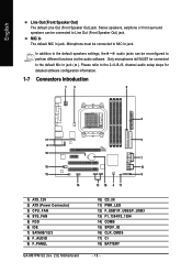
... audio software. channel audio setup steps for detailed software configuration information. 1-7 Connectors Introduction 13 6 2 17 8 16 10 15 14 1) ATX_12V 2) ATX (Power Connector) 3) CPU_FAN 4) SYS_FAN 5) FDD 6) IDE 7) SATAII0/1/2/3 8) F_AUDIO 9) F_PANEL GA-M61PM-S2 (rev. 2.0) Motherboard 5 7 12 9 13 18 4 11 10) CD_IN 11) PWR_LED 12) F_USB1/F_USB2/F_USB3 13) F1_1394/F2_1394 14) COMB 15) SPDIF_IO 16) CLR_CMOS 17) CI 18) BATTERY - 18 - English Line Out (Front Speaker Out) The default...
... audio software. channel audio setup steps for detailed software configuration information. 1-7 Connectors Introduction 13 6 2 17 8 16 10 15 14 1) ATX_12V 2) ATX (Power Connector) 3) CPU_FAN 4) SYS_FAN 5) FDD 6) IDE 7) SATAII0/1/2/3 8) F_AUDIO 9) F_PANEL GA-M61PM-S2 (rev. 2.0) Motherboard 5 7 12 9 13 18 4 11 10) CD_IN 11) PWR_LED 12) F_USB1/F_USB2/F_USB3 13) F1_1394/F2_1394 14) COMB 15) SPDIF_IO 16) CLR_CMOS 17) CI 18) BATTERY - 18 - English Line Out (Front Speaker Out) The default...
Manual
Page 20
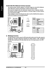
... MB and 2.88 MB. The black connector wire is used to connect the FDD cable while the other end of the foolproof groove in the FDD connector. 34 33 2 1 GA-M61PM-S2 (rev. 2.0) Motherboard - 20 - Before attaching the FDD cable, please take note of the cable connects to the FDD drive. English 3/4) CPU_FAN / SYS_FAN (Cooler Fan Power Connector) The cooler fan power connector supplies a +12V power voltage via a 3-pin (SYS_FAN)/4-pin (CPU_FAN) power connector and possesses a foolproof...
... MB and 2.88 MB. The black connector wire is used to connect the FDD cable while the other end of the foolproof groove in the FDD connector. 34 33 2 1 GA-M61PM-S2 (rev. 2.0) Motherboard - 20 - Before attaching the FDD cable, please take note of the cable connects to the FDD drive. English 3/4) CPU_FAN / SYS_FAN (Cooler Fan Power Connector) The cooler fan power connector supplies a +12V power voltage via a 3-pin (SYS_FAN)/4-pin (CPU_FAN) power connector and possesses a foolproof...
Manual
Page 21
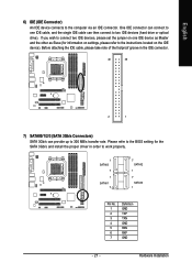
... the SATA 3Gb/s and install the proper driver in order to the computer via an IDE connector. Hardware Installation English 6) IDE (IDE Connector) An IDE device connects to work properly. 1 SATAII3 7 1 SATAII1 7 7 SATAII2 1 7 SATAII0 1 Pin No. 1 2 3 4 5 6 7 Definition GND TXP TXN GND RXN RXP GND - 21 - Please refer to the BIOS setting for information on settings, please refer to the instructions located on one IDE cable, and the single IDE cable can then connect to...
... the SATA 3Gb/s and install the proper driver in order to the computer via an IDE connector. Hardware Installation English 6) IDE (IDE Connector) An IDE device connects to work properly. 1 SATAII3 7 1 SATAII1 7 7 SATAII2 1 7 SATAII0 1 Pin No. 1 2 3 4 5 6 7 Definition GND TXP TXN GND RXN RXP GND - 21 - Please refer to the BIOS setting for information on settings, please refer to the instructions located on one IDE cable, and the single IDE cable can then connect to...
Manual
Page 22
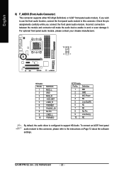
... the audio device unable to support HD Audio. GA-M61PM-S2 (rev. 2.0) Motherboard - 22 - Definition 1 MIC 2 GND 3 MIC Power 4 NC 5 Line Out (R) 6 NC 7 NC 8 No Pin 9 Line Out (L) 10 NC By default, the audio driver is configured to work or even damage it. Check the pin assignments carefully while you wish to use the front audio function, connect the front panel audio module to this connector, please refer to this connector. To connect an...
... the audio device unable to support HD Audio. GA-M61PM-S2 (rev. 2.0) Motherboard - 22 - Definition 1 MIC 2 GND 3 MIC Power 4 NC 5 Line Out (R) 6 NC 7 NC 8 No Pin 9 Line Out (L) 10 NC By default, the audio driver is configured to work or even damage it. Check the pin assignments carefully while you wish to use the front audio function, connect the front panel audio module to this connector, please refer to this connector. To connect an...
Manual
Page 23
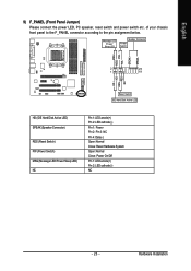
...On/Off Pin 1: LED anode(+) Pin 2: LED cathode(-) NC - 23 - English 9) F_PANEL (Front Panel Jumper) Please connect the power LED, PC speaker, reset switch and power switch etc. PW+ PWSPEAK+ SPEAK- 2 20 1 19 HD+ HD- Hardware Installation Message LED/ Power/ Sleep LED Speaker Connector Power Switch MSG+ MSG- RESRES+ NC Reset Switch IDE Hard Disk Active LED HD (IDE Hard Disk Active LED) SPEAK (Speaker Connector) RES (Reset Switch) PW (Power Switch) MSG (Message LED/Power/Sleep LED) NC Pin 1: LED anode(+) Pin 2: LED cathode(-) Pin 1: Power Pin 2- of your chassis front panel to...
...On/Off Pin 1: LED anode(+) Pin 2: LED cathode(-) NC - 23 - English 9) F_PANEL (Front Panel Jumper) Please connect the power LED, PC speaker, reset switch and power switch etc. PW+ PWSPEAK+ SPEAK- 2 20 1 19 HD+ HD- Hardware Installation Message LED/ Power/ Sleep LED Speaker Connector Power Switch MSG+ MSG- RESRES+ NC Reset Switch IDE Hard Disk Active LED HD (IDE Hard Disk Active LED) SPEAK (Speaker Connector) RES (Reset Switch) PW (Power Switch) MSG (Message LED/Power/Sleep LED) NC Pin 1: LED anode(+) Pin 2: LED cathode(-) Pin 1: Power Pin 2- of your chassis front panel to...
Manual
Page 27
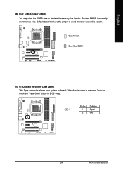
To clear CMOS, temporarily short the two pins. You can check the "Case Open" status in BIOS Setup. Open: Normal Short: Clear CMOS 17) CI (Chassis Intrusion, Case Open) This 2-pin connector allows your system to avoid improper use of this header. Definition 1 1 Signal 2 GND - 27 - Pin No. Default doesn't include the jumper to detect if the chassis cover is removed. English 16) CLR_CMOS (Clear CMOS) You may clear the CMOS data to its default values by this header. Hardware Installation
To clear CMOS, temporarily short the two pins. You can check the "Case Open" status in BIOS Setup. Open: Normal Short: Clear CMOS 17) CI (Chassis Intrusion, Case Open) This 2-pin connector allows your system to avoid improper use of this header. Definition 1 1 Signal 2 GND - 27 - Pin No. Default doesn't include the jumper to detect if the chassis cover is removed. English 16) CLR_CMOS (Clear CMOS) You may clear the CMOS data to its default values by this header. Hardware Installation
Manual
Page 30
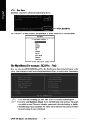
..., Hard Disk Type... 1. Select the Load Optimized Defaults item in this menu. Award Modular BIOS v6.00PG, An Energy Star Ally Copyright (C) 1984-2006, Award Software, Inc. Boot Menu == Select a Boot First device == Floppy LS120 Hard Disk CDROM ZIP USB-FDD USB-ZIP USB-CDROM USB-HDD Legacy LAN KL:Move Enter :Accept ESC:Exit The Main Menu (For example: BIOS Ver. : F4d) Once you want, press "Ctrl+F1" to access advanced options. 2. Press to accept. M61PM-S2 F4d . . . . :BIOS Setup/Q-Flash, : Xpress Recovery2, : Boot Menu 11...
..., Hard Disk Type... 1. Select the Load Optimized Defaults item in this menu. Award Modular BIOS v6.00PG, An Energy Star Ally Copyright (C) 1984-2006, Award Software, Inc. Boot Menu == Select a Boot First device == Floppy LS120 Hard Disk CDROM ZIP USB-FDD USB-ZIP USB-CDROM USB-HDD Legacy LAN KL:Move Enter :Accept ESC:Exit The Main Menu (For example: BIOS Ver. : F4d) Once you want, press "Ctrl+F1" to access advanced options. 2. Press to accept. M61PM-S2 F4d . . . . :BIOS Setup/Q-Flash, : Xpress Recovery2, : Boot Menu 11...
Manual
Page 32
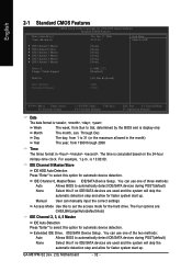
... start up . You can manually input the correct settings Access Mode Use this to select this option for automatic device detection. Day The day, from 1 to 31 (or the maximum allowed in . Extended IDE Drive. GA-M61PM-S2 (rev. 2.0) Motherboard - 32 - Through Dec. Manual User can use one of the two methods: Auto Allows BIOS to automatically detect IDE/SATA devices during POST(default) None Select this if no IDE/SATA devices are : CHS/LBA/Large/Auto(default:Auto) IDE Channel 2, 3, 4, 5 Master IDE Auto...
... start up . You can manually input the correct settings Access Mode Use this to select this option for automatic device detection. Day The day, from 1 to 31 (or the maximum allowed in . Extended IDE Drive. GA-M61PM-S2 (rev. 2.0) Motherboard - 32 - Through Dec. Manual User can use one of the two methods: Auto Allows BIOS to automatically detect IDE/SATA devices during POST(default) None Select this if no IDE/SATA devices are : CHS/LBA/Large/Auto(default:Auto) IDE Channel 2, 3, 4, 5 Master IDE Auto...
Manual
Page 39
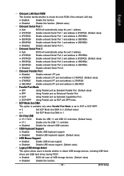
... 2.0 controllers. (Default Value) V1.1 Enable only the USB 1.1 controller. Disabled Disable USB mouse support. (Default value) Legacy USB storage detect This option allows users to decide whether to invoke the boot ROM of the onboard LAN chip. ECP Mode Use DMA This option is available only when Parallel Port Mode is 2E8/IRQ3. BIOS Setup English Onboard LAN Boot ROM This function decide whether to detect USB storage devices, including USB flash drives and USB hard drives during POST. Enabled BIOS will automatically setup the port 2 address. 3F8/IRQ4 Enable onboard Serial Port...
... 2.0 controllers. (Default Value) V1.1 Enable only the USB 1.1 controller. Disabled Disable USB mouse support. (Default value) Legacy USB storage detect This option allows users to decide whether to invoke the boot ROM of the onboard LAN chip. ECP Mode Use DMA This option is available only when Parallel Port Mode is 2E8/IRQ3. BIOS Setup English Onboard LAN Boot ROM This function decide whether to detect USB storage devices, including USB flash drives and USB hard drives during POST. Enabled BIOS will automatically setup the port 2 address. 3F8/IRQ4 Enable onboard Serial Port...
Manual
Page 44
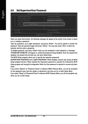
...GA-M61PM-S2 (rev. 2.0) Motherboard - 44 - If you select "Setup" at "Password Check" in creating a password. Once the password is rebooted or any time you try to enter Setup Menu. Type the password, up to confirm the password being disabled. English 2-9 Set Supervisor/User Password CMOS Setup Utility-Copyright (C) 1984-2006 Award Software ` Standard CMOS Features ` Advanced BIOS Features ` Integrated Peripherals ` Power Management Setup ` PnP/PCI ConfiguratioEnsnter Password: ` PC Health Status Load Fail-Safe Defaults Load Optimized Defaults Set Supervisor Password Set User Password...
...GA-M61PM-S2 (rev. 2.0) Motherboard - 44 - If you select "Setup" at "Password Check" in creating a password. Once the password is rebooted or any time you try to enter Setup Menu. Type the password, up to confirm the password being disabled. English 2-9 Set Supervisor/User Password CMOS Setup Utility-Copyright (C) 1984-2006 Award Software ` Standard CMOS Features ` Advanced BIOS Features ` Integrated Peripherals ` Power Management Setup ` PnP/PCI ConfiguratioEnsnter Password: ` PC Health Status Load Fail-Safe Defaults Load Optimized Defaults Set Supervisor Password Set User Password...
Manual
Page 52
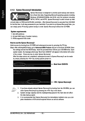
... power-on PATA and SATA IDE controllers. Save the settings and exit the BIOS Setup. Upon system restart, the message which says "Boot from CD/DVD: Award Modular BIOS v6.00PG, An Energy Star Ally Copyright (C) 1984-2006, Award Software, Inc. Boot from CD/DVD:" will affect the data backup speed. 3. Boot from CD-ROM. M61PM-S2 F4d . . . . :BIOS Setup/Q-Flash, : Xpress Recovery2, : Boot Menu 11/22/2006-NV-MCP61-6A61KG02C-00 : Xpress Recovery2 1. GA-M61PM-S2 (rev. 2.0) Motherboard...
... power-on PATA and SATA IDE controllers. Save the settings and exit the BIOS Setup. Upon system restart, the message which says "Boot from CD/DVD: Award Modular BIOS v6.00PG, An Energy Star Ally Copyright (C) 1984-2006, Award Software, Inc. Boot from CD/DVD:" will affect the data backup speed. 3. Boot from CD-ROM. M61PM-S2 F4d . . . . :BIOS Setup/Q-Flash, : Xpress Recovery2, : Boot Menu 11/22/2006-NV-MCP61-6A61KG02C-00 : Xpress Recovery2 1. GA-M61PM-S2 (rev. 2.0) Motherboard...
Manual
Page 54
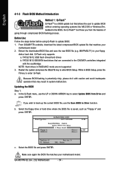
... MS-DOS or Windows.Embedded in RAID/AHCI mode are connected to enter Q-Flash. Q-Flash Utility v2.00 Flash Type/Size SST 25VF040B 512K Keep DMI Data Enable Update BIOS from the hassles of going through complicated BIOS flashing process. From GIGABYTE's website, download the latest compressed BIOS update file that may result in BIOS Setup, press the F8 key to the IDE/SATA controllers integrated with caution and avoid inadequate operation that matches your motherboard model. Because BIOS flashing is saved...
... MS-DOS or Windows.Embedded in RAID/AHCI mode are connected to enter Q-Flash. Q-Flash Utility v2.00 Flash Type/Size SST 25VF040B 512K Keep DMI Data Enable Update BIOS from the hassles of going through complicated BIOS flashing process. From GIGABYTE's website, download the latest compressed BIOS update file that may result in BIOS Setup, press the F8 key to the IDE/SATA controllers integrated with caution and avoid inadequate operation that matches your motherboard model. Because BIOS flashing is saved...

Manual
Page 56
... @BIOS Utility Fig 4. Update BIOS NOT through Internet a. Just select the desired @BIOS server to update their BIOS under Windows. Please search for BIOS unzip file, downloading from internet or any other methods (such as: M61PMS2.F1). Click "Internet Update" icon b. GA-M61PM-S2 (rev. 2.0) Motherboard - 56 - Click "Update New BIOS" c. Installing the @BIOS utility Fig 2. System will automatically download and update the BIOS. II. Installation Complete and Run @BIOS Click Start/ Programs/ Gigabyte/ BIOS/ @BIOS Select @BIOS item than click Install...
... @BIOS Utility Fig 4. Update BIOS NOT through Internet a. Just select the desired @BIOS server to update their BIOS under Windows. Please search for BIOS unzip file, downloading from internet or any other methods (such as: M61PMS2.F1). Click "Internet Update" icon b. GA-M61PM-S2 (rev. 2.0) Motherboard - 56 - Click "Update New BIOS" c. Installing the @BIOS utility Fig 2. System will automatically download and update the BIOS. II. Installation Complete and Run @BIOS Click Start/ Programs/ Gigabyte/ BIOS/ @BIOS Select @BIOS item than click Install...
Manual
Page 59
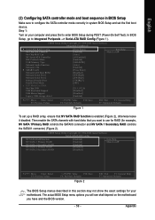
... boot sequence in BIOS Setup Make sure to Integrated Periperals --> Serial-ATA RAID Config (Figure 1). CMOS Setup Utility-Copyright (C) 1984-2006 Award Software Integrated Peripherals Serial-ATA RAID Config On-Chip IDE Channel0 On-Chip MAC Lan NV Serial-ATA Controller IDE Prefetch Mode USB Memory Type Onboard Audio Function Onboard 1394 SMART LAN Onboard LAN Boot ROM Onboard Serial Port 1 Onboard Serial Port 2 Onboard Parallel Port Parallel Port Mode x ECP Mode Use DMA On-Chip USB USB Keyboard Support USB Mouse Support Legacy USB storage detect [Press Enter] [Enabled] [Auto] [All Enabled...
... boot sequence in BIOS Setup Make sure to Integrated Periperals --> Serial-ATA RAID Config (Figure 1). CMOS Setup Utility-Copyright (C) 1984-2006 Award Software Integrated Peripherals Serial-ATA RAID Config On-Chip IDE Channel0 On-Chip MAC Lan NV Serial-ATA Controller IDE Prefetch Mode USB Memory Type Onboard Audio Function Onboard 1394 SMART LAN Onboard LAN Boot ROM Onboard Serial Port 1 Onboard Serial Port 2 Onboard Parallel Port Parallel Port Mode x ECP Mode Use DMA On-Chip USB USB Keyboard Support USB Mouse Support Legacy USB storage detect [Press Enter] [Enabled] [Auto] [All Enabled...

Manual
Page 64
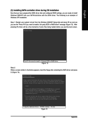
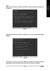
... motherboard driver CD-ROM to a floppy disk. Figure 10 Figure 11 (Note) For users without a startup disk: Use an alternative system and insert the GIGABYTE motherboard driver CD-ROM. First of all, copy the driver for the SATA controller from the menu. English (4) Making a SATA Driver Disk To install operating system onto RAID disks successfully, you need to install the SATA RAID driver during the Windows setup process. Boot from the menu in Figure 11, press K to select (K) nVIDIA MCP61 Series Raid...
... motherboard driver CD-ROM to a floppy disk. Figure 10 Figure 11 (Note) For users without a startup disk: Use an alternative system and insert the GIGABYTE motherboard driver CD-ROM. First of all, copy the driver for the SATA controller from the menu. English (4) Making a SATA Driver Disk To install operating system onto RAID disks successfully, you need to install the SATA RAID driver during the Windows setup process. Boot from the menu in Figure 11, press K to select (K) nVIDIA MCP61 Series Raid...
Manual
Page 65
...-ROM drives, or special disk controllers for which you have a device support disk from a mass storage device manufacturer, or do not want to specify additional mass storage devices for use with Windows, including those for use with the SATA driver. Windows Setup Setup could not determine the type of one or more mass storage devices installed in your system, or you see the "Press F6 if you need to install a 3rd party SCSI or RAID driver...
...-ROM drives, or special disk controllers for which you have a device support disk from a mass storage device manufacturer, or do not want to specify additional mass storage devices for use with Windows, including those for use with the SATA driver. Windows Setup Setup could not determine the type of one or more mass storage devices installed in your system, or you see the "Press F6 if you need to install a 3rd party SCSI or RAID driver...
Manual
Page 67
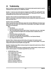
... a RAID array, the RAID driver will have to specify additional mass storage devices for that , the driver will load support for the following mass storage device(s): NVIDIA RAID CLASS DRIVER (required) NVIDIA nForce Storage Controller (required) * To specify additional SCSI adapters, CD-ROM drives, or special disk controllers for use with the Windows 2000/XP installation. Appendix After that hard drive. To repair a Windows XP installation using Recovery Console, press R. WindowsXP Professional Setup Welcome to continue the SATA driver installation from a mass storage device...
... a RAID array, the RAID driver will have to specify additional mass storage devices for that , the driver will load support for the following mass storage device(s): NVIDIA RAID CLASS DRIVER (required) NVIDIA nForce Storage Controller (required) * To specify additional SCSI adapters, CD-ROM drives, or special disk controllers for use with the Windows 2000/XP installation. Appendix After that hard drive. To repair a Windows XP installation using Recovery Console, press R. WindowsXP Professional Setup Welcome to continue the SATA driver installation from a mass storage device...
Manual
Page 73
... differ from case to the Clear CMOS steps in the battery holder to see some boards, a small amount of electricity is kept on to enter BIOS and load Fail-Safe Defaults (or load Optimized Defaults). 7. AWARD BIOS Beep Codes 1 short: System boots successfully 2 short: CMOS setting error 1 long 1 short: DRAM or M/B error 1 long 2 short: Monitor or display card error 1 long 3 short: Keyboard error 1 long 9 short: BIOS ROM error Continuous long beeps: DRAM error Continuous short beeps: Power error - 73 - Question 1: I clear CMOS? Why? Answer: If your board doesn't have such jumper, you...
... differ from case to the Clear CMOS steps in the battery holder to see some boards, a small amount of electricity is kept on to enter BIOS and load Fail-Safe Defaults (or load Optimized Defaults). 7. AWARD BIOS Beep Codes 1 short: System boots successfully 2 short: CMOS setting error 1 long 1 short: DRAM or M/B error 1 long 2 short: Monitor or display card error 1 long 3 short: Keyboard error 1 long 9 short: BIOS ROM error Continuous long beeps: DRAM error Continuous short beeps: Power error - 73 - Question 1: I clear CMOS? Why? Answer: If your board doesn't have such jumper, you...


