User Manual
Page 4
...GA-K8NE Motherboard Layout 6 Block Diagram ...7 Chapter 1 Hardware Installation 9 1-1 Considerations Prior to Installation 9 1-2 Feature Summary 10 1-3 Installation of the CPU and Heatsink 12 1-3-1 Installation of the CPU 12 1-3-2 Installation of the Heatsink 13 1-4 Installation of Memory 13 1-5 Installation of Expansion Cards 15 1-6 I/O Back Panel Introduction 16 1-7 Connectors Introduction 17 Chapter 2 BIOS... Setup 27 The Main Menu (For example: BIOS Ver. : F1b 28 2-1 Standard CMOS Features 30 2-2 Advanced BIOS Features 32 2-3 IntegratedPeripherals...
...GA-K8NE Motherboard Layout 6 Block Diagram ...7 Chapter 1 Hardware Installation 9 1-1 Considerations Prior to Installation 9 1-2 Feature Summary 10 1-3 Installation of the CPU and Heatsink 12 1-3-1 Installation of the CPU 12 1-3-2 Installation of the Heatsink 13 1-4 Installation of Memory 13 1-5 Installation of Expansion Cards 15 1-6 I/O Back Panel Introduction 16 1-7 Connectors Introduction 17 Chapter 2 BIOS... Setup 27 The Main Menu (For example: BIOS Ver. : F1b 28 2-1 Standard CMOS Features 30 2-2 Advanced BIOS Features 32 2-3 IntegratedPeripherals...
User Manual
Page 5
Chapter 3 Drivers Installation 47 3-1 Install Chipset Drivers 47 3-2 SoftwareApplication 48 3-3 Software Information 48 3-4 Hardware Information 49 3-5 Contact Us ...49 Chapter 4 Appendix 51 4-1 Unique Software Utilities 51 4-1-1 EasyTune 5 Introduction 52 4-1-2 Xpress Recovery Introduction 53 4-1-3 Flash BIOS Method Introduction 56 4-1-4 Serial ATA BIOS Setting Utility Introduction 65 4-1-5 2- / 4- / 6- / 8- Channel Audio Function Introduction 71 4-2 Troubleshooting 75 - 5 -
Chapter 3 Drivers Installation 47 3-1 Install Chipset Drivers 47 3-2 SoftwareApplication 48 3-3 Software Information 48 3-4 Hardware Information 49 3-5 Contact Us ...49 Chapter 4 Appendix 51 4-1 Unique Software Utilities 51 4-1-1 EasyTune 5 Introduction 52 4-1-2 Xpress Recovery Introduction 53 4-1-3 Flash BIOS Method Introduction 56 4-1-4 Serial ATA BIOS Setting Utility Introduction 65 4-1-5 2- / 4- / 6- / 8- Channel Audio Function Introduction 71 4-2 Troubleshooting 75 - 5 -
User Manual
Page 6
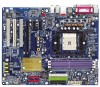
GA-K8NE Motherboard Layout LPT LAN MS/KB SPDIF_I SPDIF_O ATX_12V COMA USB Socket 754 ATX IDE2 IDE1 USB AUDIO1 AUDIO2 CPU_FAN Marvell phy F_AUDIO PCIE_1 CODEC PCIE_2 CD_IN IT8712 COMB GA-K8NE BIOS PCIE_16 PCI1 PCI2 BAT PCI3 CI FDD CLR_CMOS F_USB1 F_USB2 F_USB3 PWR_LED DDR1 DDR2 DDR3 nVIDIA® nForceTM 4(-4X) SATAII3 SATAII2 SATAII1 SATAII0 F_PANEL SYS_FAN - 6 -
GA-K8NE Motherboard Layout LPT LAN MS/KB SPDIF_I SPDIF_O ATX_12V COMA USB Socket 754 ATX IDE2 IDE1 USB AUDIO1 AUDIO2 CPU_FAN Marvell phy F_AUDIO PCIE_1 CODEC PCIE_2 CD_IN IT8712 COMB GA-K8NE BIOS PCIE_16 PCI1 PCI2 BAT PCI3 CI FDD CLR_CMOS F_USB1 F_USB2 F_USB3 PWR_LED DDR1 DDR2 DDR3 nVIDIA® nForceTM 4(-4X) SATAII3 SATAII2 SATAII1 SATAII0 F_PANEL SYS_FAN - 6 -
User Manual
Page 7
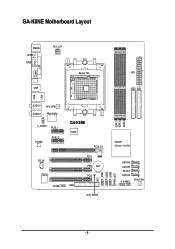
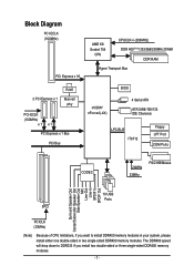
... DIMM DDR RAM Hyper Transport Bus 2 PCI Express x 1 RJ45 Marvell phy PCI-ECLK (100MHz) x1 x1 PCI Express x 1 Bus PCI Bus nVIDIA® nForce4(-4X) BIOS 4 Serial ATA ATA33/66/100/133 IDE Channels LPC BUS IT8712 Floppy LPT Port COM Ports CODEC 24MHz 33MHz PS/2 KB/Mouse Surround Speaker Out...
... DIMM DDR RAM Hyper Transport Bus 2 PCI Express x 1 RJ45 Marvell phy PCI-ECLK (100MHz) x1 x1 PCI Express x 1 Bus PCI Bus nVIDIA® nForce4(-4X) BIOS 4 Serial ATA ATA33/66/100/133 IDE Channels LPC BUS IT8712 Floppy LPT Port COM Ports CODEC 24MHz 33MHz PS/2 KB/Mouse Surround Speaker Out...
User Manual
Page 11
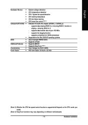
English Hardware Monitor Onboard SATA RAID Š Š BIOS Š Š Additional Features Š Š Overclocking Š Form Factor Š System voltage detection CPU temperature detection CPU / System fan speed detection CPU ... data striping (RAID 0) or mirroring (RAID 1) function or striping + mirroring (RAID 0+1) - supports data transfer rate of licensed AWARD BIOS Supports Q-Flash Supports @BIOS Supports EasyTune (Note 4) Over Voltage via BIOS (DDR) ATX form factor; 30.5cm x 22.4cm (Note 3) Whether the CPU fan speed control function is supported will depend on...
English Hardware Monitor Onboard SATA RAID Š Š BIOS Š Š Additional Features Š Š Overclocking Š Form Factor Š System voltage detection CPU temperature detection CPU / System fan speed detection CPU ... data striping (RAID 0) or mirroring (RAID 1) function or striping + mirroring (RAID 0+1) - supports data transfer rate of licensed AWARD BIOS Supports Q-Flash Supports @BIOS Supports EasyTune (Note 4) Over Voltage via BIOS (DDR) ATX form factor; 30.5cm x 22.4cm (Note 3) Whether the CPU fan speed control function is supported will depend on...
User Manual
Page 13
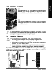
... supported by the motherboard. A memory module can be installed in one direction. Memory modules have a foolproof insertion design. The motherboard supports DDR memory modules, whereby BIOS will automatically detect memory capacity and specifications. The memory capacity used can differ with the following conditions: 1. Before installing or removing memory modules, please make...
... supported by the motherboard. A memory module can be installed in one direction. Memory modules have a foolproof insertion design. The motherboard supports DDR memory modules, whereby BIOS will automatically detect memory capacity and specifications. The memory capacity used can differ with the following conditions: 1. Before installing or removing memory modules, please make...
User Manual
Page 15
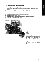
... the slot. Replace your VGA card is locked by following the steps outlined below: 1. Power on the computer, if necessary, setup BIOS utility of expansion card from the operating system. Installing a PCI Express x 16 expansion card: Please carefully pull out the small whitedrawable ... of Expansion Cards You can install your computer's chassis cover, screws and slot bracket from the computer. 3. Hardware Installation Install related driver from BIOS. 8. Please align the VGA card to the onboard PCI Express x 16 slot and press firmly down on the card are indeed seated in ...
... the slot. Replace your VGA card is locked by following the steps outlined below: 1. Power on the computer, if necessary, setup BIOS utility of expansion card from the operating system. Installing a PCI Express x 16 expansion card: Please carefully pull out the small whitedrawable ... of Expansion Cards You can install your computer's chassis cover, screws and slot bracket from the computer. 3. Hardware Installation Install related driver from BIOS. 8. Please align the VGA card to the onboard PCI Express x 16 slot and press firmly down on the card are indeed seated in ...
User Manual
Page 20
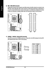
English 6) IDE1 / IDE2 (IDE Connector) An IDE device connects to work properly. Please refer to the BIOS setting for information on the IDE device). 40 39 2 IDE2 1 IDE1 7) SATAII0_1 / SATAII2_3 (Serial ATA Connector) Serial ATA can connect to one IDE device...and install the proper driver in order to the computer via an IDE connector. Pin No. Definition 1 GND 7 1 2 TXP 3 TXN 1 7 4 GND 5 RXN 6 RXP 7 GND GA-K8NE Motherboard - 20 - One IDE connector can provide up to150MB/s transfer rate. If you wish to connect two IDE devices, please set the jumper on one...
English 6) IDE1 / IDE2 (IDE Connector) An IDE device connects to work properly. Please refer to the BIOS setting for information on the IDE device). 40 39 2 IDE2 1 IDE1 7) SATAII0_1 / SATAII2_3 (Serial ATA Connector) Serial ATA can connect to one IDE device...and install the proper driver in order to the computer via an IDE connector. Pin No. Definition 1 GND 7 1 2 TXP 3 TXN 1 7 4 GND 5 RXN 6 RXP 7 GND GA-K8NE Motherboard - 20 - One IDE connector can provide up to150MB/s transfer rate. If you wish to connect two IDE devices, please set the jumper on one...
User Manual
Page 24
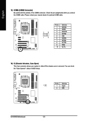
Please contact your nearest dealer for optional COMB cable. 2 10 1 9 Pin No. 1 2 3 4 5 6 7 8 9 10 Definition NDCDBNSINB NSOUTB NDTRBGND NDSRBNRTSBNCTSBNRIBNo Pin 14) CI (Chassis Intrusion, Case Open) This 2-pin connector allows your system to detect if the chassis cover is removed. Definition 1 1 Signal 2 GND GA-K8NE Motherboard - 24 - English 13) COMB (COMB Connector) Be careful with the polarity of the COMB connector. You can check the "Case Opened" status in BIOS Setup. Pin No. Check the pin assignments while you connect the COMB cable.
Please contact your nearest dealer for optional COMB cable. 2 10 1 9 Pin No. 1 2 3 4 5 6 7 8 9 10 Definition NDCDBNSINB NSOUTB NDTRBGND NDSRBNRTSBNCTSBNRIBNo Pin 14) CI (Chassis Intrusion, Case Open) This 2-pin connector allows your system to detect if the chassis cover is removed. Definition 1 1 Signal 2 GND GA-K8NE Motherboard - 24 - English 13) COMB (COMB Connector) Be careful with the polarity of the COMB connector. You can check the "Case Opened" status in BIOS Setup. Pin No. Check the pin assignments while you connect the COMB cable.
User Manual
Page 27
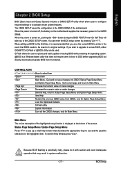
... a disk in the event that describes the appropriate keys to its original settings. Exit current page and return to a new BIOS, either GIGABYTE's Q-Flash or @BIOS utility can enter the BIOS setup screen by pressing "Ctrl + F1". You can be reset to use and the possible selections for the first time, it with caution...
... a disk in the event that describes the appropriate keys to its original settings. Exit current page and return to a new BIOS, either GIGABYTE's Q-Flash or @BIOS utility can enter the BIOS setup screen by pressing "Ctrl + F1". You can be reset to use and the possible selections for the first time, it with caution...
User Manual
Page 28
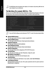
... & Exit Setup Time, Date, Hard Disk Type... The Main Menu (For example: BIOS Ver. : F1b) Once you wish to accept or enter the sub-menu. GA-K8NE Motherboard - 28 - CMOS Setup Utility-Copyright (C) 1984-2005 Award Software ` Standard CMOS Features ` Advanced BIOS Features ` Integrated Peripherals ` Power Management Setup ` PnP/PCI Configurations ` PC Health Status...
... & Exit Setup Time, Date, Hard Disk Type... The Main Menu (For example: BIOS Ver. : F1b) Once you wish to accept or enter the sub-menu. GA-K8NE Motherboard - 28 - CMOS Setup Utility-Copyright (C) 1984-2005 Award Software ` Standard CMOS Features ` Advanced BIOS Features ` Integrated Peripherals ` Power Management Setup ` PnP/PCI Configurations ` PC Health Status...

User Manual
Page 29
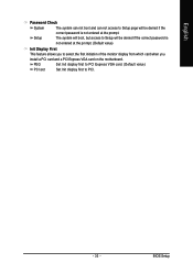
It allows you to limit access to the system and Setup, or just to CMOS and exit setup. „ Exit Without Saving Abandon all CMOS value changes and exit setup. - 29 - BIOS Setup English „ Set Supervisor Password Change, set , or disable password. It allows you to limit access to the system. „ Save & Exit Setup Save CMOS value settings to Setup. „ Set User Password Change, set , or disable password.
It allows you to limit access to the system and Setup, or just to CMOS and exit setup. „ Exit Without Saving Abandon all CMOS value changes and exit setup. - 29 - BIOS Setup English „ Set Supervisor Password Change, set , or disable password. It allows you to limit access to the system. „ Save & Exit Setup Save CMOS value settings to Setup. „ Set User Password Change, set , or disable password.
User Manual
Page 30
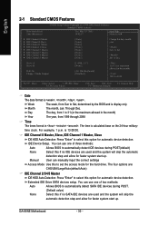
... are used and the system will skip the automatic detection step and allow for faster system start up . Jan. Extended IDE Drive SATA devices setup. GA-K8NE Motherboard - 30 - Drive A Drive B Halt On Floppy 3 Mode Support [1.44M, 3.5"] [None] [All, But Keyboard] [Disabled] 1 to 31 (or ...access mode for automatic device detection. is calculated base on the 24-hour military- User can use one of three methods: Auto Allows BIOS to automatically detect IDE devices during POST. (Default value) None Select this to 2098 KLJI: Move Enter: Select +/-/PU/PD: Value...
... are used and the system will skip the automatic detection step and allow for faster system start up . Jan. Extended IDE Drive SATA devices setup. GA-K8NE Motherboard - 30 - Drive A Drive B Halt On Floppy 3 Mode Support [1.44M, 3.5"] [None] [All, But Keyboard] [Disabled] 1 to 31 (or ...access mode for automatic device detection. is calculated base on the 24-hour military- User can use one of three methods: Auto Allows BIOS to automatically detect IDE devices during POST. (Default value) None Select this to 2098 KLJI: Move Enter: Select +/-/PU/PD: Value...
User Manual
Page 31
... category determines whether the computer will not stop if an error is 3 mode Floppy Drive. English Access Mode Use this information. All Errors Whenever the BIOS detects a non-fatal error the system will stop for all other errors. Halt on the outside drive casing. All, But Disk/Key The system boot... will stop for Japan Area) Disabled Normal Floppy Drive. (Default value) Drive A Drive A is detected during power up. BIOS Setup Floppy 3 Mode Support (for a keyboard or disk error;
... category determines whether the computer will not stop if an error is 3 mode Floppy Drive. English Access Mode Use this information. All Errors Whenever the BIOS detects a non-fatal error the system will stop for all other errors. Halt on the outside drive casing. All, But Disk/Key The system boot... will stop for Japan Area) Disabled Normal Floppy Drive. (Default value) Drive A Drive A is detected during power up. BIOS Setup Floppy 3 Mode Support (for a keyboard or disk error;
User Manual
Page 32
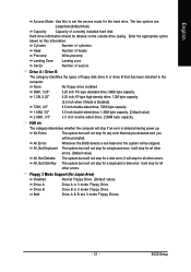
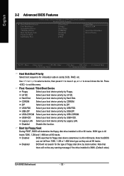
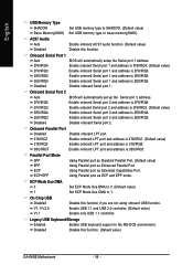
... device priority by ZIP. Disabled Disable this menu. Note that there will not be any warning message if the drive installed is 360K. (Default value) GA-K8NE Motherboard - 32 - Note that BIOS can not tell from 720K, 1.2M or 1.44M drive type as they are all 80 tracks. English 2-2 Advanced... boot device priority by USB-CDROM. USB-HDD Select your boot device priority by USB-HDD. LS120 Select your boot device priority by LS120. Disabled BIOS will determine the floppy disk drive installed is 40 or 80 tracks. 360K type is 40 or 80 tracks. Enabled...
... device priority by ZIP. Disabled Disable this menu. Note that there will not be any warning message if the drive installed is 360K. (Default value) GA-K8NE Motherboard - 32 - Note that BIOS can not tell from 720K, 1.2M or 1.44M drive type as they are all 80 tracks. English 2-2 Advanced... boot device priority by USB-CDROM. USB-HDD Select your boot device priority by USB-HDD. LS120 Select your boot device priority by LS120. Disabled BIOS will determine the floppy disk drive installed is 40 or 80 tracks. 360K type is 40 or 80 tracks. Enabled...
User Manual
Page 33
BIOS Setup The system will boot, but access to Setup will be denied if the correct password is not entered at the prompt. (Default value) Init ...
BIOS Setup The system will boot, but access to Setup will be denied if the correct password is not entered at the prompt. (Default value) Init ...
User Manual
Page 35
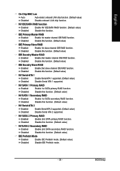
... Serial-ATA 2 Enabled Enable Serial ATA 2 supported. (Default value) Disabled Disable Serial ATA 2 supported. NV SATA 1 Primary RAID Enabled Enable 1st SATA primary RAID function. BIOS Setup Disabled Disable this function. (Default value) IDE Secndry Master RAID Enabled Enable 2nd master channel IDE RAID function. Disabled Disable this function. (Default value...
... Serial-ATA 2 Enabled Enable Serial ATA 2 supported. (Default value) Disabled Disable Serial ATA 2 supported. NV SATA 1 Primary RAID Enabled Enable 1st SATA primary RAID function. BIOS Setup Disabled Disable this function. (Default value) IDE Secndry Master RAID Enabled Enable 2nd master channel IDE RAID function. Disabled Disable this function. (Default value...
User Manual
Page 36
...). Legacy USB Keyboard/Storage Enabled Disabled Enable USB keyboard support in the MS-DOS environment. Onboard Serial Port 1 Auto 3F8/IRQ4 BIOS will automatically set up the Serial port 2 address. 3F8/IRQ4 Enable onboard Serial port 2 and address is 3F8/IRQ4. 2F8/... Enable onboard Serial port 2 and address is 3E8/IRQ4. Disabled Disable onboard Serial port 2. On-Chip USB Disabled Disable this function. (Default value) GA-K8NE Motherboard - 36 - V1.1+V2.0 Enable USB 1.1 and USB 2.0 controller. (Default value) V1.1 Enable only USB 1.1 controller. AC97 Audio Auto ...
...). Legacy USB Keyboard/Storage Enabled Disabled Enable USB keyboard support in the MS-DOS environment. Onboard Serial Port 1 Auto 3F8/IRQ4 BIOS will automatically set up the Serial port 2 address. 3F8/IRQ4 Enable onboard Serial port 2 and address is 3F8/IRQ4. 2F8/... Enable onboard Serial port 2 and address is 3E8/IRQ4. Disabled Disable onboard Serial port 2. On-Chip USB Disabled Disable this function. (Default value) GA-K8NE Motherboard - 36 - V1.1+V2.0 Enable USB 1.1 and USB 2.0 controller. (Default value) V1.1 Enable only USB 1.1 controller. AC97 Audio Auto ...
User Manual
Page 37
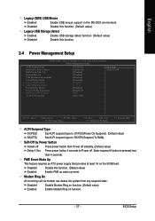
... function. (Default value) Enabled Enable PME as wake up event. English Legacy (DOS) USB Mouse Enabled Enable USB mouse support in the MS-DOS environment. BIOS Setup Disabled Disable this function. 2-4 Power Management Setup CMOS Setup Utility-Copyright (C) 1984-2005 Award Software Power Management Setup ACPI Suspend Type Soft-Off by...
... function. (Default value) Enabled Enable PME as wake up event. English Legacy (DOS) USB Mouse Enabled Enable USB mouse support in the MS-DOS environment. BIOS Setup Disabled Disable this function. 2-4 Power Management Setup CMOS Setup Utility-Copyright (C) 1984-2005 Award Software Power Management Setup ACPI Suspend Type Soft-Off by...
User Manual
Page 39
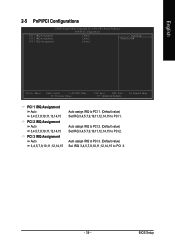
BIOS Setup Auto assign IRQ to PCI 3. (Default value) Set IRQ 3,4,5,7,9,10,11,12,14,15 to PCI 1. English 2-5 PnP/PCI Configurations CMOS Setup Utility-Copyright (C) ...
BIOS Setup Auto assign IRQ to PCI 3. (Default value) Set IRQ 3,4,5,7,9,10,11,12,14,15 to PCI 1. English 2-5 PnP/PCI Configurations CMOS Setup Utility-Copyright (C) ...


