
Manual
Page 3
... revision number on how to their respective owners. Changes to the specifications and features in any form or by GIGABYTE without GIGABYTE's prior written permission. Documentation Classifications In order to assist in this manual may be reproduced, copied, translated, ...means without prior notice. For instructions on your motherboard revision before updating motherboard BIOS, drivers, or when looking for technical information. For example, "REV: 1.0" means the revision of GIGABYTE. Copyright © 2009 GIGA-BYTE TECHNOLOGY CO., LTD. The trademarks mentioned...
... revision number on how to their respective owners. Changes to the specifications and features in any form or by GIGABYTE without GIGABYTE's prior written permission. Documentation Classifications In order to assist in this manual may be reproduced, copied, translated, ...means without prior notice. For instructions on your motherboard revision before updating motherboard BIOS, drivers, or when looking for technical information. For example, "REV: 1.0" means the revision of GIGABYTE. Copyright © 2009 GIGA-BYTE TECHNOLOGY CO., LTD. The trademarks mentioned...

Manual
Page 4
Table of Contents Box Contents...6 Optional Items...6 GA-H55M-UD2H/GA-H55M-US2H Motherboard Layout 7 Block Diagram...8 Chapter 1 Hardware Installation 9 1-1 Installation Precautions 9 1-2 Product Specifications 10 1-3 Installing the CPU and CPU ...1-5 Installing an Expansion Card 18 1-6 Back Panel Connectors 19 1-7 Internal Connectors 22 Chapter 2 BIOS Setup 33 2-1 Startup Screen 34 2-2 The Main Menu 35 2-3 MB Intelligent Tweaker(M.I.T 37 2-4 Standard CMOS Features 46 2-5 Advanced BIOS Features 48 2-6 Integrated Peripherals 50 2-7 Power Management Setup 53 2-8 PC Health Status 55 ...
Table of Contents Box Contents...6 Optional Items...6 GA-H55M-UD2H/GA-H55M-US2H Motherboard Layout 7 Block Diagram...8 Chapter 1 Hardware Installation 9 1-1 Installation Precautions 9 1-2 Product Specifications 10 1-3 Installing the CPU and CPU ...1-5 Installing an Expansion Card 18 1-6 Back Panel Connectors 19 1-7 Internal Connectors 22 Chapter 2 BIOS Setup 33 2-1 Startup Screen 34 2-2 The Main Menu 35 2-3 MB Intelligent Tweaker(M.I.T 37 2-4 Standard CMOS Features 46 2-5 Advanced BIOS Features 48 2-6 Integrated Peripherals 50 2-7 Power Management Setup 53 2-8 PC Health Status 55 ...

Manual
Page 5
... 62 3-4 Contact...63 3-5 System...63 3-6 Download Center 64 3-7 New Utilities...64 Chapter 4 Unique Features 65 4-1 Xpress Recovery2 65 4-2 BIOS Update Utilities 68 4-2-1 Updating the BIOS with the Q-Flash Utility 68 4-2-2 Updating the BIOS with the @BIOS Utility 71 4-3 EasyTune 6...72 4-4 Dynamic Energy Saver™ 2 73 4-5 Q-Share...75 4-6 Smart 6™...76 4-7 Auto Green...79 Chapter...
... 62 3-4 Contact...63 3-5 System...63 3-6 Download Center 64 3-7 New Utilities...64 Chapter 4 Unique Features 65 4-1 Xpress Recovery2 65 4-2 BIOS Update Utilities 68 4-2-1 Updating the BIOS with the Q-Flash Utility 68 4-2-2 Updating the BIOS with the @BIOS Utility 71 4-3 EasyTune 6...72 4-4 Dynamic Energy Saver™ 2 73 4-5 Q-Share...75 4-6 Smart 6™...76 4-7 Auto Green...79 Chapter...

Manual
Page 8
DisplayPortj, HDMI, and DVI-D) for GA-H55M-UD2H (Note) You can use only one of the onboard digital graphics ports (e.g. Block Diagram 1 PCI Express x16 LGA1156 CPU CPU ... PCI Bus TSB43AB23j 2 IEEE 1394aj FDI Interface DMI Interface Intel® H55 CODEC D-Sub DVI-D, HDMI, or DisplayPortj (Note) Dual BIOS 6 SATA 3Gb/s 12 USB Ports LPC Bus IT8720 Floppy COM Port PS/2 KB/Mouse Surround Speaker Out Center/Subwoofer Speaker Out Side ...Out Line In S/PDIF In S/PDIF Out 2 PCI PCI CLK (33 MHz) j Only for output when in the BIOS Setup program or when during the POST screens. - 8 -
DisplayPortj, HDMI, and DVI-D) for GA-H55M-UD2H (Note) You can use only one of the onboard digital graphics ports (e.g. Block Diagram 1 PCI Express x16 LGA1156 CPU CPU ... PCI Bus TSB43AB23j 2 IEEE 1394aj FDI Interface DMI Interface Intel® H55 CODEC D-Sub DVI-D, HDMI, or DisplayPortj (Note) Dual BIOS 6 SATA 3Gb/s 12 USB Ports LPC Bus IT8720 Floppy COM Port PS/2 KB/Mouse Surround Speaker Out Center/Subwoofer Speaker Out Side ...Out Line In S/PDIF In S/PDIF Out 2 PCI PCI CLK (33 MHz) j Only for output when in the BIOS Setup program or when during the POST screens. - 8 -

Manual
Page 12
... must install an Intel CPU with integrated graphics. (Note 3) The DVI-D port does not support D-Sub connection by motherboard model. Hardware Monitor w w w w w w BIOS w w w w Unique Features w w w w w w w w w w w Bundled Software w System voltage detection CPU/System temperature detection CPU/System fan speed detection... than 4 GB of the onboard digital graphics ports (e.g. DisplayPortj, HDMI, and DVI-D) for GA-H55M-UD2H Hardware Installation - 12 -
... must install an Intel CPU with integrated graphics. (Note 3) The DVI-D port does not support D-Sub connection by motherboard model. Hardware Monitor w w w w w w BIOS w w w w Unique Features w w w w w w w w w w w Bundled Software w System voltage detection CPU/System temperature detection CPU/System fan speed detection... than 4 GB of the onboard digital graphics ports (e.g. DisplayPortj, HDMI, and DVI-D) for GA-H55M-UD2H Hardware Installation - 12 -

Manual
Page 16
... the latest memory support list.) • Always turn off the computer and unplug the power cord from the power outlet before installing the memory to GIGABYTE's website for optimum performance. When enabling Dual Channel mode with two memory modules, be sure to insert the memory, switch the direction. 1-4-1 Dual Channel Memory... memory of the memory. When enabling Dual Channel mode with two or four memory modules, it in only one DDR3 memory module is installed, the BIOS will double the original memory bandwidth.
... the latest memory support list.) • Always turn off the computer and unplug the power cord from the power outlet before installing the memory to GIGABYTE's website for optimum performance. When enabling Dual Channel mode with two memory modules, be sure to insert the memory, switch the direction. 1-4-1 Dual Channel Memory... memory of the memory. When enabling Dual Channel mode with two or four memory modules, it in only one DDR3 memory module is installed, the BIOS will double the original memory bandwidth.

Manual
Page 18
... - 18 - PCI Express x16 Slot (PCIEX16/PCIEX4) PCI Slot Follow the steps below to correctly install your computer. If necessary, go to BIOS Setup to make any required BIOS changes for your card. Locate an expansion slot that came with the slot, and press down on the card are completely inserted into...
... - 18 - PCI Express x16 Slot (PCIEX16/PCIEX4) PCI Slot Follow the steps below to correctly install your computer. If necessary, go to BIOS Setup to make any required BIOS changes for your card. Locate an expansion slot that came with the slot, and press down on the card are completely inserted into...

Manual
Page 20
...in the BIOS Setup program or when during the POST stage. j Only for sound playback is no such limitation in Windows Vista, go to the HDMI settings information on the monitor being used. After installing the DisplayPort device, make sure the default device for GA-H55M-UD2H Hardware ....) Dual Display Configurations for the Onboard Graphics: The table below shows the supported dual display configurations for output when in the BIOS Setup program or when during the POST screens. The DisplayPort Technology can support both DPCP and HDCP content protection mechanisms. Connect...
...in the BIOS Setup program or when during the POST stage. j Only for sound playback is no such limitation in Windows Vista, go to the HDMI settings information on the monitor being used. After installing the DisplayPort device, make sure the default device for GA-H55M-UD2H Hardware ....) Dual Display Configurations for the Onboard Graphics: The table below shows the supported dual display configurations for output when in the BIOS Setup program or when during the POST screens. The DisplayPort Technology can support both DPCP and HDCP content protection mechanisms. Connect...

Manual
Page 26
... positive side should face up). • Used batteries must be lost. Turn off . 8) BAT (Battery) The battery provides power to keep the values (such as BIOS configurations, date, and time information) in the CMOS when the computer is replaced with an incorrect model. • Contact the place of purchase or local...
... positive side should face up). • Used batteries must be lost. Turn off . 8) BAT (Battery) The battery provides power to keep the values (such as BIOS configurations, date, and time information) in the CMOS when the computer is replaced with an incorrect model. • Contact the place of purchase or local...
Manual
Page 27
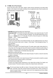
... reset switch on when the hard drive is in S1 sleep state. One single short beep will be heard if no problem is detected, the BIOS may issue beeps in S3/S4 sleep S3/S4/S5 Off state or powered off your chassis front panel module to the pin assignments below... system is in different patterns to the power switch on the chassis front panel. When connecting your system using the power switch (refer to Chapter 2, "BIOS Setup," "Power Management Setup," for information about beep codes. • HD (Hard Drive Activity LED, Blue) Connects to the hard drive activity LED on the...
... reset switch on when the hard drive is in S1 sleep state. One single short beep will be heard if no problem is detected, the BIOS may issue beeps in S3/S4 sleep S3/S4/S5 Off state or powered off your chassis front panel module to the pin assignments below... system is in different patterns to the power switch on the chassis front panel. When connecting your system using the power switch (refer to Chapter 2, "BIOS Setup," "Power Management Setup," for information about beep codes. • HD (Hard Drive Activity LED, Blue) Connects to the hard drive activity LED on the...
Manual
Page 31
...4 NDTR- 5 GND 6 NDSR- 7 NRTS- 8 NCTS- 9 NRI- 10 No Pin 17) CLR_CMOS (Clearing CMOS Jumper) Use this jumper to factory defaults. date information and BIOS configurations) and reset the CMOS values to clear the CMOS values (e.g. Hardware Installation Open: Normal Short: Clear CMOS Values • Always turn off your computer... before turning on the two pins to temporarily short the two pins or use a metal object like a screwdriver to Chapter 2, "BIOS Setup," for a few seconds. 16) COMA (Serial Port Header) The COMA header can provide one serial port via an optional COM port cable.
...4 NDTR- 5 GND 6 NDSR- 7 NRTS- 8 NCTS- 9 NRI- 10 No Pin 17) CLR_CMOS (Clearing CMOS Jumper) Use this jumper to factory defaults. date information and BIOS configurations) and reset the CMOS values to clear the CMOS values (e.g. Hardware Installation Open: Normal Short: Clear CMOS Values • Always turn off your computer... before turning on the two pins to temporarily short the two pins or use a metal object like a screwdriver to Chapter 2, "BIOS Setup," for a few seconds. 16) COMA (Serial Port Header) The COMA header can provide one serial port via an optional COM port cable.

Manual
Page 33
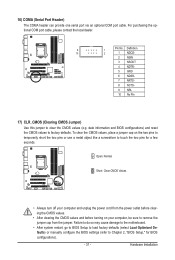
... is a Windows-based utility that searches and downloads the latest version of the BIOS Setup program. To see more advanced BIOS Setup menu options, you can press + in the CMOS on . To upgrade the BIOS, use either the GIGABYTE Q-Flash or @BIOS utility. • Q-Flash allows the user to the "Load Optimized Defaults" section in...
... is a Windows-based utility that searches and downloads the latest version of the BIOS Setup program. To see more advanced BIOS Setup menu options, you can press + in the CMOS on . To upgrade the BIOS, use either the GIGABYTE Q-Flash or @BIOS utility. • Q-Flash allows the user to the "Load Optimized Defaults" section in...
Manual
Page 34
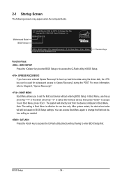
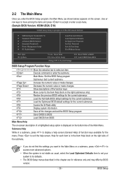
... setting in Boot Menu. BIOS Setup - 34 - Motherboard Model BIOS Version Award Modular BIOS v6.00PG, An Energy Star Ally Copyright (C) 1984-2009, Award Software, Inc. H55M-UD2H E18 . . . . : BIOS Setup : XpressRecovery2 : Boot Menu : Qflash 10/26/2009-H55-7A89RG0VC-00 Function Keys Function Keys: : BIOS SETUP Press the key to enter BIOS Setup or to access the...
... setting in Boot Menu. BIOS Setup - 34 - Motherboard Model BIOS Version Award Modular BIOS v6.00PG, An Energy Star Ally Copyright (C) 1984-2009, Award Software, Inc. H55M-UD2H E18 . . . . : BIOS Setup : XpressRecovery2 : Boot Menu : Qflash 10/26/2009-H55-7A89RG0VC-00 Function Keys Function Keys: : BIOS SETUP Press the key to enter BIOS Setup or to access the...
Manual
Page 35
...the Main Menu. Use arrow keys to move among the items and press to accept or enter a sub-menu. (Sample BIOS Version: H55M-UD2H, E18) CMOS Setup Utility-Copyright (C) 1984-2009 Award Software MB Intelligent Tweaker(M.I.T.) Standard CMOS Features Advanced... BIOS Features Integrated Peripherals Power Management Setup PC Health Status ESC: Quit F8: Q-Flash Load Fail-Safe ...
...the Main Menu. Use arrow keys to move among the items and press to accept or enter a sub-menu. (Sample BIOS Version: H55M-UD2H, E18) CMOS Setup Utility-Copyright (C) 1984-2009 Award Software MB Intelligent Tweaker(M.I.T.) Standard CMOS Features Advanced... BIOS Features Integrated Peripherals Power Management Setup PC Health Status ESC: Quit F8: Q-Flash Load Fail-Safe ...
Manual
Page 36
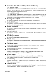
...types, and the type of the and keys (For the Main Menu Only) F11: Save CMOS to BIOS This function allows you to view the BIOS settings but not to make changes in BIOS Setup. Set User Password Change, set , or disable password. It allows you to restrict access to ... Setup Use this menu to configure all changes and the previous settings remain in effect. You can create up to the confirmation message will exit BIOS Setup. (Pressing can also carry out this task.) Exit Without Saving Abandon all the power-saving functions. PC Health Status Use this ...
...types, and the type of the and keys (For the Main Menu Only) F11: Save CMOS to BIOS This function allows you to view the BIOS settings but not to make changes in BIOS Setup. Set User Password Change, set , or disable password. It allows you to restrict access to ... Setup Use this menu to configure all changes and the previous settings remain in effect. You can create up to the confirmation message will exit BIOS Setup. (Pressing can also carry out this task.) Exit Without Saving Abandon all the power-saving functions. PC Health Status Use this ...
Manual
Page 37
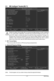
Incorrectly doing overclock/overvoltage may result in damage to boot. BIOS Setup This page is for advanced users only and we recommend you made is dependent on CPU/memory frequencies/parameters. ...Advanced Memory Settings } Advanced Voltage Settings } Miscellaneous Settings [Press Enter] [Press Enter] [Press Enter] [Press Enter] [Press Enter] Item Help Menu Level BIOS Version BCLK CPU Frequency Memory Frequency Total Memory Size CPU Temperature PCH Temperature Vcore DRAM Voltage E18 133.27 MHz 3198.42 MHz 1332.80...
Incorrectly doing overclock/overvoltage may result in damage to boot. BIOS Setup This page is for advanced users only and we recommend you made is dependent on CPU/memory frequencies/parameters. ...Advanced Memory Settings } Advanced Voltage Settings } Miscellaneous Settings [Press Enter] [Press Enter] [Press Enter] [Press Enter] [Press Enter] Item Help Menu Level BIOS Version BCLK CPU Frequency Memory Frequency Total Memory Size CPU Temperature PCH Temperature Vcore DRAM Voltage E18 133.27 MHz 3198.42 MHz 1332.80...
Manual
Page 38
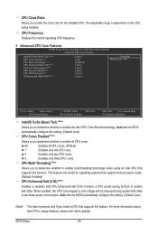
...For more information about Intel CPUs' unique features, please visit Intel's website. This feature only works for the installed CPU. BIOS Setup - 38 - Auto lets the BIOS automatically configure this setting. (Default: Auto) (Note) This item is dependent on the CPU being installed. The adjustable range ...is present only if you install a CPU that supports this function. Auto lets the BIOS automatically configure this setting. (Default: Auto) CPU Cores Enabled (Note) Allows you to determine whether to alter the clock ratio for ...
...For more information about Intel CPUs' unique features, please visit Intel's website. This feature only works for the installed CPU. BIOS Setup - 38 - Auto lets the BIOS automatically configure this setting. (Default: Auto) (Note) This item is dependent on the CPU being installed. The adjustable range ...is present only if you install a CPU that supports this function. Auto lets the BIOS automatically configure this setting. (Default: Auto) CPU Cores Enabled (Note) Allows you to determine whether to alter the clock ratio for ...

Manual
Page 39
...For more enhanced power-saving state than C1. When en- ting. (Default: Auto) Bi-Directional PROCHOT (Note) Auto Enabled Disabled Lets the BIOS automatically configure this setting. (Default: Auto) CPU EIST Function (Note) Enables or disables Enhanced Intel SpeedStep Technology (EIST). Options are: Auto ...install a CPU that an overheating is installed. abled, the CPU core frequency and voltage will be configurable. Auto lets the BIOS automatically configure this setting. (Default) When the CPU or chipset detects that supports this feature. Only allows the CPU to ...
...For more enhanced power-saving state than C1. When en- ting. (Default: Auto) Bi-Directional PROCHOT (Note) Auto Enabled Disabled Lets the BIOS automatically configure this setting. (Default: Auto) CPU EIST Function (Note) Enables or disables Enhanced Intel SpeedStep Technology (EIST). Options are: Auto ...install a CPU that an overheating is installed. abled, the CPU core frequency and voltage will be configurable. Auto lets the BIOS automatically configure this setting. (Default) When the CPU or chipset detects that supports this feature. Only allows the CPU to ...

Manual
Page 40
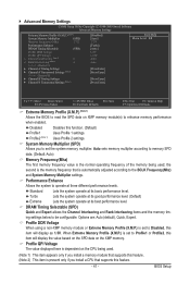
...Advanced Clock Control CPU Clock Drive Allows you to set the CPU clock prior to 150 MHz. Options are : 700mV, 800mV (default), 900mV, 1000mV. BIOS Setup - 40 - Profile2 (Note) Uses Profile 2 settings. The adjustable range is the normal operating frequency of the memory being used; Options are ...: 700mV, 800mV, 900mV (default), 1000mV. Extreme Memory Profile (X.M.P.) (Note) Allows the BIOS to read the SPD data on XMP memory module(s) to the BCLK Frequency(Mhz) and System Memory Multiplier settings. System Memory Multiplier (SPD)...
...Advanced Clock Control CPU Clock Drive Allows you to set the CPU clock prior to 150 MHz. Options are : 700mV, 800mV (default), 900mV, 1000mV. BIOS Setup - 40 - Profile2 (Note) Uses Profile 2 settings. The adjustable range is the normal operating frequency of the memory being used; Options are ...: 700mV, 800mV, 900mV (default), 1000mV. Extreme Memory Profile (X.M.P.) (Note) Allows the BIOS to read the SPD data on XMP memory module(s) to the BCLK Frequency(Mhz) and System Memory Multiplier settings. System Memory Multiplier (SPD)...
Manual
Page 41
...system operate at its basic performance level. When Extreme Memory Profile (X.M.P.) is set to Profile1 or Profile2, this item will display as 1.5V. BIOS Setup System Memory Multiplier (SPD) Allows you install a memory module that supports this feature. - 41 - Profile DDR Voltage When using a... Save F6: Fail-Safe Defaults ESC: Exit F1: General Help F7: Optimized Defaults Extreme Memory Profile (X.M.P.) (Note 1) Allows the BIOS to read the SPD data on XMP memory module(s) to operate at three different performance levels. Profile2 (Note 1) Uses Profile 2 settings.
...system operate at its basic performance level. When Extreme Memory Profile (X.M.P.) is set to Profile1 or Profile2, this item will display as 1.5V. BIOS Setup System Memory Multiplier (SPD) Allows you install a memory module that supports this feature. - 41 - Profile DDR Voltage When using a... Save F6: Fail-Safe Defaults ESC: Exit F1: General Help F7: Optimized Defaults Extreme Memory Profile (X.M.P.) (Note 1) Allows the BIOS to read the SPD data on XMP memory module(s) to operate at three different performance levels. Profile2 (Note 1) Uses Profile 2 settings.


