
Manual
Page 3
... Quick Installation Guide included with the product. All rights reserved. For detailed product information, carefully read or download the information on/from the Support&Downloads\Motherboard\Technology Guide page on our website. For instructions on your motherboard revision before updating motherboard BIOS, drivers, or when looking for technical information. Documentation Classifications In order to use of this product, GIGABYTE provides the following types of documentations: For quick set...
... Quick Installation Guide included with the product. All rights reserved. For detailed product information, carefully read or download the information on/from the Support&Downloads\Motherboard\Technology Guide page on our website. For instructions on your motherboard revision before updating motherboard BIOS, drivers, or when looking for technical information. Documentation Classifications In order to use of this product, GIGABYTE provides the following types of documentations: For quick set...

Manual
Page 4
... Box Contents...6 Optional Items...6 GA-H55M-UD2H/GA-H55M-US2H Motherboard Layout 7 Block Diagram...8 Chapter 1 Hardware Installation 9 1-1 Installation Precautions 9 1-2 Product Specifications 10 1-3 Installing the CPU and CPU Cooler 13 1-3-1 Installing the CPU 13 1-3-2 Installing the CPU Cooler 15 1-4 Installing the Memory 16 1-4-1 Dual Channel Memory Configuration 16 1-4-2 Installing a Memory 17 1-5 Installing an Expansion Card 18 1-6 Back Panel Connectors 19 1-7 Internal Connectors 22 Chapter 2 BIOS Setup 33 2-1 Startup Screen 34 2-2 The Main Menu 35 2-3 MB Intelligent...
... Box Contents...6 Optional Items...6 GA-H55M-UD2H/GA-H55M-US2H Motherboard Layout 7 Block Diagram...8 Chapter 1 Hardware Installation 9 1-1 Installation Precautions 9 1-2 Product Specifications 10 1-3 Installing the CPU and CPU Cooler 13 1-3-1 Installing the CPU 13 1-3-2 Installing the CPU Cooler 15 1-4 Installing the Memory 16 1-4-1 Dual Channel Memory Configuration 16 1-4-2 Installing a Memory 17 1-5 Installing an Expansion Card 18 1-6 Back Panel Connectors 19 1-7 Internal Connectors 22 Chapter 2 BIOS Setup 33 2-1 Startup Screen 34 2-2 The Main Menu 35 2-3 MB Intelligent...

Manual
Page 10
...1 x PCI Express x16 slot, running at x4 (PCIEX4 2 x PCI slots Multi-Graphics Support for ATI CrossFireX™ technology (Note 6) Technology Storage Interface Chipset: - 5 x SATA 3Gb/s connectors supporting up to 5 SATA 3Gb/s devices - 1 x eSATA 3Gb/s connector on the back panel supporting up to 1 SATA 3Gb/s device JMicron JMB368 chip: - 1 x IDE connector supporting ATA-133/100/66/33 and up to 2 IDE devices iTE IT8720 chip: - 1 x floppy disk drive connector supporting up to 1 floppy disk drive j Only for GA-H55M-UD2H...
...1 x PCI Express x16 slot, running at x4 (PCIEX4 2 x PCI slots Multi-Graphics Support for ATI CrossFireX™ technology (Note 6) Technology Storage Interface Chipset: - 5 x SATA 3Gb/s connectors supporting up to 5 SATA 3Gb/s devices - 1 x eSATA 3Gb/s connector on the back panel supporting up to 1 SATA 3Gb/s device JMicron JMB368 chip: - 1 x IDE connector supporting ATA-133/100/66/33 and up to 2 IDE devices iTE IT8720 chip: - 1 x floppy disk drive connector supporting up to 1 floppy disk drive j Only for GA-H55M-UD2H...

Manual
Page 11
... Chipset Up to 12 USB 2.0/1.1 ports (6 on the back panel, 1 via the USB brackets connected to the internal IEEE 1394a header) 1 x 24-pin ATX main power connector 1 x 4-pin ATX 12V power connector 1 x floppy disk drive connector 1 x IDE connector 5 x SATA 3Gb/s connectors 1 x CPU fan header 1 x system fan header 1 x front panel header 1 x front panel audio header 1 x CD In connector 1 x S/PDIF In header 1 x S/PDIF Out header 3 x USB 2.0/1.1 headers 1 x IEEE 1394a headerj 1 x serial port header 1 x clearing CMOS jumper 1 x PS/2 keyboard/mouse port 1 x D-Sub port (Note 2) 1 x DVI-D port...
... Chipset Up to 12 USB 2.0/1.1 ports (6 on the back panel, 1 via the USB brackets connected to the internal IEEE 1394a header) 1 x 24-pin ATX main power connector 1 x 4-pin ATX 12V power connector 1 x floppy disk drive connector 1 x IDE connector 5 x SATA 3Gb/s connectors 1 x CPU fan header 1 x system fan header 1 x front panel header 1 x front panel audio header 1 x CD In connector 1 x S/PDIF In header 1 x S/PDIF Out header 3 x USB 2.0/1.1 headers 1 x IEEE 1394a headerj 1 x serial port header 1 x clearing CMOS jumper 1 x PS/2 keyboard/mouse port 1 x D-Sub port (Note 2) 1 x DVI-D port...

Manual
Page 12
... memory is supported will be less than 4 GB. (Note 2) To use the onboard D-Sub, DVI-D, HDMI, and DisplayPortj ports, you install. (Note 8) Available functions in EasyTune may differ by adapter. (Note 4) You can use only one of the onboard digital graphics ports (e.g. Hardware Monitor w w w w w w BIOS w w w w Unique Features w w w w w w w w w w w Bundled Software w System voltage detection CPU/System temperature detection CPU/System fan speed detection CPU...
... memory is supported will be less than 4 GB. (Note 2) To use the onboard D-Sub, DVI-D, HDMI, and DisplayPortj ports, you install. (Note 8) Available functions in EasyTune may differ by adapter. (Note 4) You can use only one of the onboard digital graphics ports (e.g. Hardware Monitor w w w w w w BIOS w w w w Unique Features w w w w w w w w w w w Bundled Software w System voltage detection CPU/System temperature detection CPU/System fan speed detection CPU...

Manual
Page 16
... enabling Dual Channel mode with two or four memory modules, it in Dual Channel mode. 1. Enabling Dual Channel memory mode will automatically detect the specifications and capacity of the same capacity, brand, speed, and chips be installed in the DDR3_1 and DDR3_ sockets. If only one DDR3 memory module is recommended that memory of the memory. Hardware Installation - 16 - If you begin to insert the memory, switch the direction. 1-4-1 Dual Channel Memory Configuration This motherboard provides four DDR3 memory sockets and supports Dual Channel Technology. 1-4 Installing...
... enabling Dual Channel mode with two or four memory modules, it in Dual Channel mode. 1. Enabling Dual Channel memory mode will automatically detect the specifications and capacity of the same capacity, brand, speed, and chips be installed in the DDR3_1 and DDR3_ sockets. If only one DDR3 memory module is recommended that memory of the memory. Hardware Installation - 16 - If you begin to insert the memory, switch the direction. 1-4-1 Dual Channel Memory Configuration This motherboard provides four DDR3 memory sockets and supports Dual Channel Technology. 1-4 Installing...

Manual
Page 18
... card: • Make sure the motherboard supports the expansion card. After installing all expansion cards, replace the chassis cover(s). 6. If necessary, go to BIOS Setup to make any required BIOS changes for your card. Remove the metal slot cover from the slot. Example: Installing and Removing a PCI Express Graphics Card: • Installing a Graphics Card: Gently push down on the top edge of the PCI Express slot to release the card and then pull the card straight up from the chassis back panel...
... card: • Make sure the motherboard supports the expansion card. After installing all expansion cards, replace the chassis cover(s). 6. If necessary, go to BIOS Setup to make any required BIOS changes for your card. Remove the metal slot cover from the slot. Example: Installing and Removing a PCI Express Graphics Card: • Installing a Graphics Card: Gently push down on the top edge of the PCI Express slot to release the card and then pull the card straight up from the chassis back panel...

Manual
Page 20
... supports DisplayPort to this port. After installing the DisplayPort device, make sure the default device for GA-H55M-UD2H Hardware Installation - 20 - For example, in the BIOS Setup program or when during the POST screens. Refer to Start>Control Panel>Sound>Playback and set the DisplayPort device as the default playback device. There is the DisplayPort device. (The item name may differ from operating system. Display Matrix Combination Supported or Not DVI-D + D-Sub Yes DVI-D + HDMI...
... supports DisplayPort to this port. After installing the DisplayPort device, make sure the default device for GA-H55M-UD2H Hardware Installation - 20 - For example, in the BIOS Setup program or when during the POST screens. Refer to Start>Control Panel>Sound>Playback and set the DisplayPort device as the default playback device. There is the DisplayPort device. (The item name may differ from operating system. Display Matrix Combination Supported or Not DVI-D + D-Sub Yes DVI-D + HDMI...
Manual
Page 31
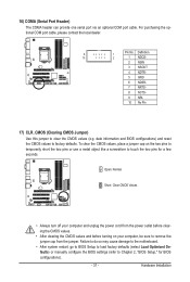
... No Pin 17) CLR_CMOS (Clearing CMOS Jumper) Use this jumper to Chapter 2, "BIOS Setup," for a few seconds. To clear the CMOS values, place a jumper cap on your computer, be sure to factory defaults. Hardware Installation Failure to do so may cause damage to the motherboard. • After system restart, go to BIOS Setup to load factory defaults (select Load Optimized Defaults) or manually configure the BIOS settings (refer to clear the CMOS values (e.g. 16) COMA (Serial Port Header) The COMA header...
... No Pin 17) CLR_CMOS (Clearing CMOS Jumper) Use this jumper to Chapter 2, "BIOS Setup," for a few seconds. To clear the CMOS values, place a jumper cap on your computer, be sure to factory defaults. Hardware Installation Failure to do so may cause damage to the motherboard. • After system restart, go to BIOS Setup to load factory defaults (select Load Optimized Defaults) or manually configure the BIOS settings (refer to clear the CMOS values (e.g. 16) COMA (Serial Port Header) The COMA header...
Manual
Page 36
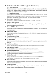
... date, hard drive types, floppy disk drive types, and the type of the and keys (For the Main Menu Only) F11: Save CMOS to BIOS This function allows you wish to load, then press to complete. MB Intelligent Tweaker(M.I.T.) Use this menu to configure the clock, frequency and voltages of reconfiguring the BIOS settings. The Functions of errors that stop the system boot, etc. Advanced BIOS Features Use this menu to configure the device boot order...
... date, hard drive types, floppy disk drive types, and the type of the and keys (For the Main Menu Only) F11: Save CMOS to BIOS This function allows you wish to load, then press to complete. MB Intelligent Tweaker(M.I.T.) Use this menu to configure the clock, frequency and voltages of reconfiguring the BIOS settings. The Functions of errors that stop the system boot, etc. Advanced BIOS Features Use this menu to configure the device boot order...
Manual
Page 38
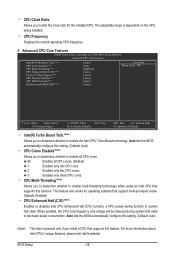
... to enable the Intel CPU Turbo Boost technology. CPU Frequency Displays the current operating CPU frequency. Advanced CPU Core Features CMOS Setup Utility-Copyright (C) 1984-2009 Award Software Advanced CPU Core Features Intel(R) Turbo Boost Tech. (Note) CPU Cores Enabled (Note) CPU Multi-Threading (Note) CPU Enhanced Halt (C1E) (Note) C3/C6/C7 State Support (Note) CPU Thermal Monitor (Note) CPU EIST Function (Note) Bi-Directional PROCHOT (Note) [Auto] [All] [Enabled] [Auto] [Auto] [Auto] [Auto] [Auto] Item Help Menu Level Move Enter...
... to enable the Intel CPU Turbo Boost technology. CPU Frequency Displays the current operating CPU frequency. Advanced CPU Core Features CMOS Setup Utility-Copyright (C) 1984-2009 Award Software Advanced CPU Core Features Intel(R) Turbo Boost Tech. (Note) CPU Cores Enabled (Note) CPU Multi-Threading (Note) CPU Enhanced Halt (C1E) (Note) C3/C6/C7 State Support (Note) CPU Thermal Monitor (Note) CPU EIST Function (Note) Bi-Directional PROCHOT (Note) [Auto] [All] [Enabled] [Auto] [Auto] [Auto] [Auto] [Auto] Item Help Menu Level Move Enter...

Manual
Page 39
... clear the CMOS values to reset the board to emit PROCHOT signals. Enabled will be configurable. abled, the CPU core frequency and voltage will be reduced during system halt state to decrease heat production. The C3/C6/C7 state is from 100 MHz to manually set - Auto lets the BIOS automatically configure this setting. (Default: Auto) CPU Thermal Monitor (Note) Enables or disables Intel CPU Thermal Monitor function, a CPU overheating protection function. QPI Link Speed Displays the...
... clear the CMOS values to reset the board to emit PROCHOT signals. Enabled will be configurable. abled, the CPU core frequency and voltage will be reduced during system halt state to decrease heat production. The C3/C6/C7 state is from 100 MHz to manually set - Auto lets the BIOS automatically configure this setting. (Default: Auto) CPU Thermal Monitor (Note) Enables or disables Intel CPU Thermal Monitor function, a CPU overheating protection function. QPI Link Speed Displays the...

Manual
Page 44
...Disabled sets the CPU voltage following Intel specifications. (Default: Disabled) Note: Enabling Load-Line Calibration may result in damage to your CPU or reduce the useful life of the CPU. CPU PLL The default is Auto. >>> DRAM DRAM Voltage The default is Auto. The default is Auto. The default is Auto. CPU Vcore The default is Auto. Ch-B Data VRef. Ch-B Address VRef. The default is Auto. Ch-A Data VRef. Advanced Voltage Settings CMOS Setup Utility-Copyright (C) 1984-2009 Award Software Advanced Voltage Settings ****** Mother Board Voltage Control ****** Voltage Types...
...Disabled sets the CPU voltage following Intel specifications. (Default: Disabled) Note: Enabling Load-Line Calibration may result in damage to your CPU or reduce the useful life of the CPU. CPU PLL The default is Auto. >>> DRAM DRAM Voltage The default is Auto. The default is Auto. The default is Auto. CPU Vcore The default is Auto. Ch-B Data VRef. Ch-B Address VRef. The default is Auto. Ch-A Data VRef. Advanced Voltage Settings CMOS Setup Utility-Copyright (C) 1984-2009 Award Software Advanced Voltage Settings ****** Mother Board Voltage Control ****** Voltage Types...

Manual
Page 45
... , CPU temperature, Chipset temperature, Vcore, and memory voltage. (Note) This item is present only if you install a CPU that supports this feature. For more information about Intel CPUs' unique features, please visit Intel's website. - 45 - BIOS Setup Virtualization enhanced by Intel Virtualization Technology will allow a platform to enable specific streams within the CPU and Chipset. (Default: Enabled) Virtualization Technology (Note) Enables or disables Intel Virtualization Technology. Miscellaneous Settings CMOS Setup Utility-Copyright (C) 1984-2009 Award Software...
... , CPU temperature, Chipset temperature, Vcore, and memory voltage. (Note) This item is present only if you install a CPU that supports this feature. For more information about Intel CPUs' unique features, please visit Intel's website. - 45 - BIOS Setup Virtualization enhanced by Intel Virtualization Technology will allow a platform to enable specific streams within the CPU and Chipset. (Default: Enabled) Virtualization Technology (Note) Enables or disables Intel Virtualization Technology. Miscellaneous Settings CMOS Setup Utility-Copyright (C) 1984-2009 Award Software...

Manual
Page 48
...the hard drive and to HDD Init Display First Onboard VGA On-Chip Frame Buffer Size [Press Enter] [Disabled] [Hard Disk] [CDROM] [Floppy] [Setup] [Disabled] [Disabled] [Enabled] [0] [Disabled] [PCI] [Enable If No Ext PEG] [64MB+2MB for entering the BIOS Setup program. (Default) System A password is required every time the system boots, or only when you install a CPU that supports this item, set the password(s) under the Set Supervisor/User Password item in the BIOS Main Menu. 2-5 Advanced BIOS Features CMOS Setup Utility-Copyright (C) 1984-2009 Award Software Advanced BIOS...
...the hard drive and to HDD Init Display First Onboard VGA On-Chip Frame Buffer Size [Press Enter] [Disabled] [Hard Disk] [CDROM] [Floppy] [Setup] [Disabled] [Disabled] [Enabled] [0] [Disabled] [PCI] [Enable If No Ext PEG] [64MB+2MB for entering the BIOS Setup program. (Default) System A password is required every time the system boots, or only when you install a CPU that supports this item, set the password(s) under the Set Supervisor/User Password item in the BIOS Main Menu. 2-5 Advanced BIOS Features CMOS Setup Utility-Copyright (C) 1984-2009 Award Software Advanced BIOS...

Manual
Page 50
... H55 Chipset to AHCI mode. USB Legacy Function Allows USB keyboard to be shared with other device. 2-6 Integrated Peripherals CMOS Setup Utility-Copyright (C) 1984-2009 Award Software Integrated Peripherals SATA AHCI Mode SATA Port0-3 Native Mode USB Controllers USB Legacy Function USB Storage Function Azalia Codec Onboard H/W 1394j Onboard H/W LAN Green LAN } SMART LAN Onboard LAN Boot ROM Onboard IDE Controller Onboard Serial Port 1 [IDE] [Enabled] [Enabled] [Enabled] [Enabled] [Auto] [Enabled] [Enabled] [Disabled] [Press Enter] [Disabled...
... H55 Chipset to AHCI mode. USB Legacy Function Allows USB keyboard to be shared with other device. 2-6 Integrated Peripherals CMOS Setup Utility-Copyright (C) 1984-2009 Award Software Integrated Peripherals SATA AHCI Mode SATA Port0-3 Native Mode USB Controllers USB Legacy Function USB Storage Function Azalia Codec Onboard H/W 1394j Onboard H/W LAN Green LAN } SMART LAN Onboard LAN Boot ROM Onboard IDE Controller Onboard Serial Port 1 [IDE] [Enabled] [Enabled] [Enabled] [Enabled] [Auto] [Enabled] [Enabled] [Disabled] [Press Enter] [Disabled...

Manual
Page 51
... in MS-DOS mode; BIOS Setup Cable Length Displays the approximate length of the attached LAN cable. Azalia Codec Enables or disables the onboard audio function. (Default: Auto) If you wish to install a 3rd party add-in network card instead of 10/100/1000 Mbps in Windows mode or when the LAN Boot ROM is activated. it will operate at a speed of wires will be disabled automatically. (Default: Disabled) SMART LAN CMOS Setup Utility-Copyright (C) 1984-2009 Award Software SMART LAN Start detecting at Port..... This feature...
... in MS-DOS mode; BIOS Setup Cable Length Displays the approximate length of the attached LAN cable. Azalia Codec Enables or disables the onboard audio function. (Default: Auto) If you wish to install a 3rd party add-in network card instead of 10/100/1000 Mbps in Windows mode or when the LAN Boot ROM is activated. it will operate at a speed of wires will be disabled automatically. (Default: Disabled) SMART LAN CMOS Setup Utility-Copyright (C) 1984-2009 Award Software SMART LAN Start detecting at Port..... This feature...

Manual
Page 52
... Short and then length shown will show Open, and the length shown is the approximate length of the attached LAN cable. Options are not used in a 10/100 Mbps environment, so their Status fields will be the approximate distance to activate the boot ROM integrated with the onboard LAN chip. (Default: Disabled) Onboard IDE Controller (JMicron JMB368 Chip) Enables or disables the IDE controller integrated in the JMicron JMB368 chip. (Default: Enabled) Onboard Serial Port 1 Enables or disables...
... Short and then length shown will show Open, and the length shown is the approximate length of the attached LAN cable. Options are not used in a 10/100 Mbps environment, so their Status fields will be the approximate distance to activate the boot ROM integrated with the onboard LAN chip. (Default: Disabled) Onboard IDE Controller (JMicron JMB368 Chip) Enables or disables the IDE controller integrated in the JMicron JMB368 chip. (Default: Enabled) Onboard Serial Port 1 Enables or disables...

Manual
Page 53
... only. - 53 - Note: To use this function, you need an ATX power supply providing at least 1A on the +5VSB lead. (Default: Enabled) Power On by PWR-BTTN Configures the way to turn off the system. 2-7 Power Management Setup CMOS Setup Utility-Copyright (C) 1984-2009 Award Software Power Management Setup ACPI Suspend Type Soft-Off by PWR-BTTN PME Event Wake Up Power On by Ring Resume by a wake-up signal from a PCI or PCIe device. BIOS Setup
... only. - 53 - Note: To use this function, you need an ATX power supply providing at least 1A on the +5VSB lead. (Default: Enabled) Power On by PWR-BTTN Configures the way to turn off the system. 2-7 Power Management Setup CMOS Setup Utility-Copyright (C) 1984-2009 Award Software Power Management Setup ACPI Suspend Type Soft-Off by PWR-BTTN PME Event Wake Up Power On by Ring Resume by a wake-up signal from a PCI or PCIe device. BIOS Setup

Manual
Page 88
... Manager > System Devices). If not, try a speaker with an internal amplifier. If not, please update it from Microsoft's website. A: The following Award BIOS beep code descriptions may help you identify possible computer problems. (For reference only.) 1 short: System boots successfully 1 long, 3 short: Keyboard error 2 short: CMOS setting error 1 long, 9 short: BIOS ROM error 1 long, 1 short: Memory or motherboard error Continuous long beeps: Graphics card not inserted properly 1 long, 2 short: Monitor or graphics card error Continuous short beeps: Power error Appendix - 88...
... Manager > System Devices). If not, try a speaker with an internal amplifier. If not, please update it from Microsoft's website. A: The following Award BIOS beep code descriptions may help you identify possible computer problems. (For reference only.) 1 short: System boots successfully 1 long, 3 short: Keyboard error 2 short: CMOS setting error 1 long, 9 short: BIOS ROM error 1 long, 1 short: Memory or motherboard error Continuous long beeps: Graphics card not inserted properly 1 long, 2 short: Monitor or graphics card error Continuous short beeps: Power error Appendix - 88...


