Manual
Page 3
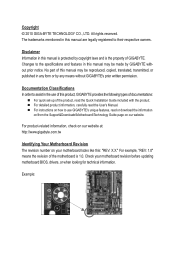
...reserved. The trademarks mentioned in this : "REV: X.X." For product-related information, check on our website at: http://www.gigabyte.com.tw Identifying Your Motherboard Revision The revision number on our website. Example: Changes to their respective owners. No part ...\Motherboard\Technology Guide page on your motherboard revision before updating motherboard BIOS, drivers, or when looking for technical information. Check your motherboard looks like this manual is protected by GIGABYTE without GIGABYTE's prior written permission. For example, "REV: 1.0" means the...
...reserved. The trademarks mentioned in this : "REV: X.X." For product-related information, check on our website at: http://www.gigabyte.com.tw Identifying Your Motherboard Revision The revision number on our website. Example: Changes to their respective owners. No part ...\Motherboard\Technology Guide page on your motherboard revision before updating motherboard BIOS, drivers, or when looking for technical information. Check your motherboard looks like this manual is protected by GIGABYTE without GIGABYTE's prior written permission. For example, "REV: 1.0" means the...

Manual
Page 4
Table of Contents Box Contents...6 Optional Items...6 GA-H55M-D2H Motherboard Layout 7 GA-H55M-D2H Motherboard Block Diagram 8 Chapter 1 Hardware Installation 9 1-1 Installation Precautions 9 1-2 Product Specifications 10 1-3 Installing the CPU and CPU ... an Expansion Card 18 1-6 Back Panel Connectors 19 1-7 Internal Connectors 21 Chapter 2 BIOS Setup 31 2-1 Startup Screen 32 2-2 The Main Menu 33 2-3 MB Intelligent Tweaker(M.I.T 35 2-4 Standard CMOS Features 43 2-5 Advanced BIOS Features 45 2-6 Integrated Peripherals 47 2-7 Power Management Setup 50 2-8 PC Health Status ...
Table of Contents Box Contents...6 Optional Items...6 GA-H55M-D2H Motherboard Layout 7 GA-H55M-D2H Motherboard Block Diagram 8 Chapter 1 Hardware Installation 9 1-1 Installation Precautions 9 1-2 Product Specifications 10 1-3 Installing the CPU and CPU ... an Expansion Card 18 1-6 Back Panel Connectors 19 1-7 Internal Connectors 21 Chapter 2 BIOS Setup 31 2-1 Startup Screen 32 2-2 The Main Menu 33 2-3 MB Intelligent Tweaker(M.I.T 35 2-4 Standard CMOS Features 43 2-5 Advanced BIOS Features 45 2-6 Integrated Peripherals 47 2-7 Power Management Setup 50 2-8 PC Health Status ...

Manual
Page 5
... 58 3-4 Contact...59 3-5 System...59 3-6 Download Center 60 3-7 New Utilities...60 Chapter 4 Unique Features 61 4-1 Xpress Recovery2 61 4-2 BIOS Update Utilities 64 4-2-1 Updating the BIOS with the Q-Flash Utility 64 4-2-2 Updating the BIOS with the @BIOS Utility 67 4-3 EasyTune 6...68 4-4 Dynamic Energy Saver™ 2 69 4-5 Q-Share...71 4-6 Smart 6™...72 4-7 Auto Green...75 Chapter...
... 58 3-4 Contact...59 3-5 System...59 3-6 Download Center 60 3-7 New Utilities...60 Chapter 4 Unique Features 61 4-1 Xpress Recovery2 61 4-2 BIOS Update Utilities 64 4-2-1 Updating the BIOS with the Q-Flash Utility 64 4-2-2 Updating the BIOS with the @BIOS Utility 67 4-3 EasyTune 6...68 4-4 Dynamic Energy Saver™ 2 69 4-5 Q-Share...71 4-6 Smart 6™...72 4-7 Auto Green...75 Chapter...
Manual
Page 8
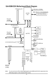
GA-H55M-D2H Motherboard Block Diagram 1 PCI Express x16 CPU CLK+/- (133 MHz) LGA1156 CPU DDR3 1666 (O.C.)/1333/1066/800 MHz Dual Channel Memory PCIe...33 IDE Channel x1 JMicron JMB368 PCI Bus Intel® H55 CODEC FDI Interface DMI Interface D-Sub DVI-D (Note) HDMI (Note) Dual BIOS 6 SATA 3Gb/s 12 USB Ports LPC Bus iTE IT8720 Floppy COM Port PS/2 KB/Mouse Surround Speaker Out Center/Subwoofer Speaker Out Side ...33 MHz) (Note) You can use only one of the onboard digital graphics ports (HDMI and DVI-D) for output when in the BIOS Setup program or when during the POST screens. - 8 -
GA-H55M-D2H Motherboard Block Diagram 1 PCI Express x16 CPU CLK+/- (133 MHz) LGA1156 CPU DDR3 1666 (O.C.)/1333/1066/800 MHz Dual Channel Memory PCIe...33 IDE Channel x1 JMicron JMB368 PCI Bus Intel® H55 CODEC FDI Interface DMI Interface D-Sub DVI-D (Note) HDMI (Note) Dual BIOS 6 SATA 3Gb/s 12 USB Ports LPC Bus iTE IT8720 Floppy COM Port PS/2 KB/Mouse Surround Speaker Out Center/Subwoofer Speaker Out Side ...33 MHz) (Note) You can use only one of the onboard digital graphics ports (HDMI and DVI-D) for output when in the BIOS Setup program or when during the POST screens. - 8 -
Manual
Page 12
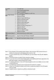
...w w w w w w Bundled Software w 2 x 64 Mbit flash Use of licensed AWARD BIOS Support for DualBIOS™ PnP 1.0a, DMI 2.0, SM BIOS 2.4, ACPI 1.0b Support for @BIOS Support for Q-Flash Support for Xpress BIOS Rescue Support for Download Center Support for Xpress Install Support for Xpress Recovery2 Support for EasyTune (Note 8)...(Note 4) You can use only one of the onboard digital graphics ports (HDMI and DVI-D) for output when in the BIOS Setup program or when during the POST screens. (Note 5) For optimum performance, if only one PCI Express graphics card is...
...w w w w w w Bundled Software w 2 x 64 Mbit flash Use of licensed AWARD BIOS Support for DualBIOS™ PnP 1.0a, DMI 2.0, SM BIOS 2.4, ACPI 1.0b Support for @BIOS Support for Q-Flash Support for Xpress BIOS Rescue Support for Download Center Support for Xpress Install Support for Xpress Recovery2 Support for EasyTune (Note 8)...(Note 4) You can use only one of the onboard digital graphics ports (HDMI and DVI-D) for output when in the BIOS Setup program or when during the POST screens. (Note 5) For optimum performance, if only one PCI Express graphics card is...
Manual
Page 16
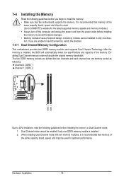
... the specifications and capacity of the same capacity, brand, speed, and chips be used . (Go to GIGABYTE's website for optimum performance. When enabling Dual Channel mode with two memory modules, it is installed, the BIOS will double the original memory bandwidth. If you begin to install the memory: • Make sure that...
... the specifications and capacity of the same capacity, brand, speed, and chips be used . (Go to GIGABYTE's website for optimum performance. When enabling Dual Channel mode with two memory modules, it is installed, the BIOS will double the original memory bandwidth. If you begin to install the memory: • Make sure that...
Manual
Page 18
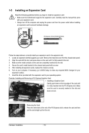
...) PCI Slot Follow the steps below to correctly install your card. Remove the metal slot cover from the slot. If necessary, go to BIOS Setup to make any required BIOS changes for your operating system. Hardware Installation - 18 - Locate an expansion slot that came with a screw. 5. Make sure the metal contacts on...
...) PCI Slot Follow the steps below to correctly install your card. Remove the metal slot cover from the slot. If necessary, go to BIOS Setup to make any required BIOS changes for your operating system. Hardware Installation - 18 - Locate an expansion slot that came with a screw. 5. Make sure the metal contacts on...
Manual
Page 19
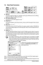
... audio output only supports AC3, DTS and 2-channel-LPCM formats. (AC3 and DTS require the use of an external decoder for output when in the BIOS Setup program or when during the POST screens. - 19 - Connect a monitor that supports D-Sub connection to the DVI-D specification and supports a maximum resolution of the...
... audio output only supports AC3, DTS and 2-channel-LPCM formats. (AC3 and DTS require the use of an external decoder for output when in the BIOS Setup program or when during the POST screens. - 19 - Connect a monitor that supports D-Sub connection to the DVI-D specification and supports a maximum resolution of the...
Manual
Page 20
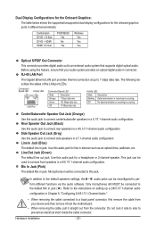
... ports in a 5.1/7.1-channel audio configuration. This jack can be connected to this audio jack to prevent an electrical short inside the cable connector. Combination POST/BIOS Windows DVI-D + D-Sub Yes Yes DVI-D + HDMI No Yes HDMI + D-Sub Yes Yes Optical S/PDIF Out Connector This connector provides digital audio out to connect...
... ports in a 5.1/7.1-channel audio configuration. This jack can be connected to this audio jack to prevent an electrical short inside the cable connector. Combination POST/BIOS Windows DVI-D + D-Sub Yes Yes DVI-D + HDMI No Yes HDMI + D-Sub Yes Yes Optical S/PDIF Out Connector This connector provides digital audio out to connect...
Manual
Page 25
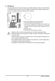
8) BAT (Battery) The battery provides power to keep the values (such as BIOS configurations, date, and time information) in the CMOS when the computer is replaced with an incorrect model. • Contact the place of purchase or local ...
8) BAT (Battery) The battery provides power to keep the values (such as BIOS configurations, date, and time information) in the CMOS when the computer is replaced with an incorrect model. • Contact the place of purchase or local ...

Manual
Page 26
... problem is in different patterns to the reset switch on the chassis front panel. The LED is on when the hard drive is detected, the BIOS may differ by issuing a beep code. This function requires a chassis with a chassis intrusion switch/sensor. If a problem is reading or writing data. &#... front panel. The front panel design may issue beeps in S1 sleep state. When connecting your system using the power switch (refer to Chapter 2, "BIOS Setup," "Power Management Setup," for information about beep codes. • HD (Hard Drive Activity LED, Blue) Connects to this header, make sure ...
... problem is in different patterns to the reset switch on the chassis front panel. The LED is on when the hard drive is detected, the BIOS may differ by issuing a beep code. This function requires a chassis with a chassis intrusion switch/sensor. If a problem is reading or writing data. &#... front panel. The front panel design may issue beeps in S1 sleep state. When connecting your system using the power switch (refer to Chapter 2, "BIOS Setup," "Power Management Setup," for information about beep codes. • HD (Hard Drive Activity LED, Blue) Connects to this header, make sure ...
Manual
Page 30
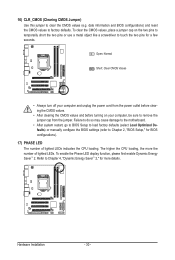
...damage to the motherboard. • After system restart, go to BIOS Setup to load factory defaults (select Load Optimized Defaults) or manually configure the BIOS settings (refer to Chapter 4, "Dynamic Energy Saver™ 2," for BIOS configurations). 17) PHASE LED The number of lighted LEDs. To ...enable the Phase LED display function, please first enable Dynamic Energy Saver™ 2. Refer to Chapter 2, "BIOS Setup," for more the number of lighted LEDs indicates the CPU loading. Hardware Installation - 30 - The higher the CPU loading, the more ...
...damage to the motherboard. • After system restart, go to BIOS Setup to load factory defaults (select Load Optimized Defaults) or manually configure the BIOS settings (refer to Chapter 4, "Dynamic Energy Saver™ 2," for BIOS configurations). 17) PHASE LED The number of lighted LEDs. To ...enable the Phase LED display function, please first enable Dynamic Energy Saver™ 2. Refer to Chapter 2, "BIOS Setup," for more the number of lighted LEDs indicates the CPU loading. Hardware Installation - 30 - The higher the CPU loading, the more ...

Manual
Page 31
...searches and downloads the latest version of BIOS from the Internet and updates the BIOS. Chapter 2 BIOS Setup BIOS (Basic Input and Output System) records hardware parameters of the system in the CMOS on . To upgrade the BIOS, use either the GIGABYTE Q-Flash or @BIOS utility. • Q-Flash allows ...the user to Chapter 4, "BIOS Update Utilities." • Because BIOS flashing is potentially risky, if you do it is turned off, the battery ...
...searches and downloads the latest version of BIOS from the Internet and updates the BIOS. Chapter 2 BIOS Setup BIOS (Basic Input and Output System) records hardware parameters of the system in the CMOS on . To upgrade the BIOS, use either the GIGABYTE Q-Flash or @BIOS utility. • Q-Flash allows ...the user to Chapter 4, "BIOS Update Utilities." • Because BIOS flashing is potentially risky, if you do it is turned off, the battery ...
Manual
Page 32
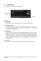
H55M-D2H E2 . . . . : BIOS Setup : XpressRecovery2 : Boot Menu : Qflash 04/30/2010-H55-7A89TG0FC-00 Function Keys Function Keys: : BIOS SETUP Press the key to enter BIOS Setup or to access the Q-Flash utility in Boot Menu. You can be based on BIOS Setup settings. BIOS Setup - 32 - For more information,...may appear when the computer boots. Note: The setting in Boot Menu is effective for subsequent access to enter BIOS Setup first. Motherboard Model BIOS Version Award Modular BIOS v6.00PG, An Energy Star Ally Copyright (C) 1984-2010, Award Software, Inc. To exit Boot Menu,...
H55M-D2H E2 . . . . : BIOS Setup : XpressRecovery2 : Boot Menu : Qflash 04/30/2010-H55-7A89TG0FC-00 Function Keys Function Keys: : BIOS SETUP Press the key to enter BIOS Setup or to access the Q-Flash utility in Boot Menu. You can be based on BIOS Setup settings. BIOS Setup - 32 - For more information,...may appear when the computer boots. Note: The setting in Boot Menu is effective for subsequent access to enter BIOS Setup first. Motherboard Model BIOS Version Award Modular BIOS v6.00PG, An Energy Star Ally Copyright (C) 1984-2010, Award Software, Inc. To exit Boot Menu,...

Manual
Page 33
... User Password Save & Exit Setup Exit Without Saving Select Item F10: Save & Exit Setup Change CPU's Clock & Voltage F11: Save CMOS to BIOS F12: Load CMOS from BIOS BIOS Setup Program Function Keys Move the selection bar to select an item Execute command or enter the submenu Main Menu: Exit the... of a highlighted setup option is in the Item Help block on the bottom line of function keys available for reference only and may differ by BIOS version. - 33 - Submenu Help While in this chapter are for the menu. Press to display a help screen. Help for each item is ...
... User Password Save & Exit Setup Exit Without Saving Select Item F10: Save & Exit Setup Change CPU's Clock & Voltage F11: Save CMOS to BIOS F12: Load CMOS from BIOS BIOS Setup Program Function Keys Move the selection bar to select an item Execute command or enter the submenu Main Menu: Exit the... of a highlighted setup option is in the Item Help block on the bottom line of function keys available for reference only and may differ by BIOS version. - 33 - Submenu Help While in this chapter are for the menu. Press to display a help screen. Help for each item is ...

Manual
Page 34
... and date, hard drive types, floppy disk drive types, and the type of errors that stop the system boot, etc. Advanced BIOS Features Use this menu to configure the device boot order, advanced features available on the CPU, and the primary display adapter. Integrated ..., USB, integrated audio, and integrated LAN, etc. Power Management Setup Use this menu to configure all changes and the previous settings remain in BIOS Setup. Set User Password Change, set , or disable password. First select the profile you to make changes. Save & Exit Setup...
... and date, hard drive types, floppy disk drive types, and the type of errors that stop the system boot, etc. Advanced BIOS Features Use this menu to configure the device boot order, advanced features available on the CPU, and the primary display adapter. Integrated ..., USB, integrated audio, and integrated LAN, etc. Power Management Setup Use this menu to configure all changes and the previous settings remain in BIOS Setup. Set User Password Change, set , or disable password. First select the profile you to make changes. Save & Exit Setup...

Manual
Page 35
... Frequency Settings } Advanced Memory Settings } Advanced Voltage Settings } Miscellaneous Settings [Press Enter] [Press Enter] [Press Enter] [Press Enter] [Press Enter] Item Help Menu Level BIOS Version BCLK CPU Frequency Memory Frequency Total Memory Size CPU Temperature PCH Temperature Vcore DRAM Voltage E2 133.27 MHz 3198.42 MHz 1332.80...: General Help F7: Optimized Defaults Whether the system will work stably with the overclock/overvoltage settings you install a memory module that supports this feature. - 35 - BIOS Setup
... Frequency Settings } Advanced Memory Settings } Advanced Voltage Settings } Miscellaneous Settings [Press Enter] [Press Enter] [Press Enter] [Press Enter] [Press Enter] Item Help Menu Level BIOS Version BCLK CPU Frequency Memory Frequency Total Memory Size CPU Temperature PCH Temperature Vcore DRAM Voltage E2 133.27 MHz 3198.42 MHz 1332.80...: General Help F7: Optimized Defaults Whether the system will work stably with the overclock/overvoltage settings you install a memory module that supports this feature. - 35 - BIOS Setup

Manual
Page 36
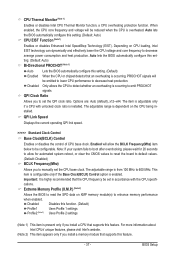
... (Note) Allows you to determine whether to let the CPU enter C3/C6/C7 mode in system halt state. Auto lets the BIOS automatically configure this feature. When enabled, the CPU core frequency and voltage will be reduced during system halt state to decrease power consumption.... Auto lets the BIOS automatically configure this function. This feature only works for the installed CPU. BIOS Setup - 36 - CPU Frequency Displays the current operating CPU frequency. Advanced CPU Core ...
... (Note) Allows you to determine whether to let the CPU enter C3/C6/C7 mode in system halt state. Auto lets the BIOS automatically configure this feature. When enabled, the CPU core frequency and voltage will be reduced during system halt state to decrease power consumption.... Auto lets the BIOS automatically configure this function. This feature only works for the installed CPU. BIOS Setup - 36 - CPU Frequency Displays the current operating CPU frequency. Advanced CPU Core ...
Manual
Page 37
... only if you install a CPU that the CPU frequency be configurable. Auto lets the BIOS automatically configure this setting. (Default: Auto) Bi-Directional PROCHOT (Note 1) Auto Lets the BIOS automatically configure this setting. (Default) Enabled When the CPU or chipset detects that supports ...to decrease average power consumption and heat production. Auto lets the BIOS automatically configure this feature. - 37 - Disabled Disables this feature. BIOS Setup Extreme Memory Profile (X.M.P.) (Note 2) Allows the BIOS to read the SPD data on CPU loading, Intel EIST technology...
... only if you install a CPU that the CPU frequency be configurable. Auto lets the BIOS automatically configure this setting. (Default: Auto) Bi-Directional PROCHOT (Note 1) Auto Lets the BIOS automatically configure this setting. (Default) Enabled When the CPU or chipset detects that supports ...to decrease average power consumption and heat production. Auto lets the BIOS automatically configure this feature. - 37 - Disabled Disables this feature. BIOS Setup Extreme Memory Profile (X.M.P.) (Note 2) Allows the BIOS to read the SPD data on CPU loading, Intel EIST technology...

Manual
Page 38
... Clock Drive Allows you to adjust the amplitude of the PCI Express and Chipset clock. the second is the memory frequency that supports this feature. BIOS Setup - 38 - PCI Express Frequency(Mhz) Allows you to manually set the PCIe clock frequency. Options are: 700mV, 800mV, 900mV (default), 1000mV...
... Clock Drive Allows you to adjust the amplitude of the PCI Express and Chipset clock. the second is the memory frequency that supports this feature. BIOS Setup - 38 - PCI Express Frequency(Mhz) Allows you to manually set the PCIe clock frequency. Options are: 700mV, 800mV, 900mV (default), 1000mV...


