Manual
Page 3
... order to their respective owners. Example: No part of this manual are legally registered to assist in the use GIGABYTE's unique features, read or download the information on/from the Support&Downloads\Motherboard\Technology Guide page on your motherboard revision before updating motherboard BIOS, drivers, or when looking for technical information. Disclaimer Information in any form or by GIGABYTE without GIGABYTE's prior written permission. For product-related...
... order to their respective owners. Example: No part of this manual are legally registered to assist in the use GIGABYTE's unique features, read or download the information on/from the Support&Downloads\Motherboard\Technology Guide page on your motherboard revision before updating motherboard BIOS, drivers, or when looking for technical information. Disclaimer Information in any form or by GIGABYTE without GIGABYTE's prior written permission. For product-related...
Manual
Page 4
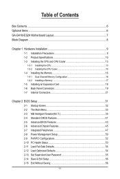
Table of Contents Box Contents...6 Optional Items...6 GA-G41M-ES2H Motherboard Layout 7 Block Diagram...8 Chapter 1 Hardware Installation 9 1-1 Installation Precautions 9 1-2 Product Specifications 10 1-3 Installing the CPU and CPU Cooler 13 1-3-1 Installing the CPU 13 1-3-2 Installing the CPU Cooler 15 1-4 Installing the Memory 16 1-4-1 Dual Channel Memory Configuration 16 1-4-2 Installing a Memory 17 1-5 Installing an Expansion Card 18 1-6 Back Panel Connectors 19 1-7 Internal Connectors 21 Chapter 2 BIOS Setup 31 2-1 Startup Screen 32 2-2 The Main Menu 33 2-3 MB Intelligent ...
Table of Contents Box Contents...6 Optional Items...6 GA-G41M-ES2H Motherboard Layout 7 Block Diagram...8 Chapter 1 Hardware Installation 9 1-1 Installation Precautions 9 1-2 Product Specifications 10 1-3 Installing the CPU and CPU Cooler 13 1-3-1 Installing the CPU 13 1-3-2 Installing the CPU Cooler 15 1-4 Installing the Memory 16 1-4-1 Dual Channel Memory Configuration 16 1-4-2 Installing a Memory 17 1-5 Installing an Expansion Card 18 1-6 Back Panel Connectors 19 1-7 Internal Connectors 21 Chapter 2 BIOS Setup 31 2-1 Startup Screen 32 2-2 The Main Menu 33 2-3 MB Intelligent ...
Manual
Page 6
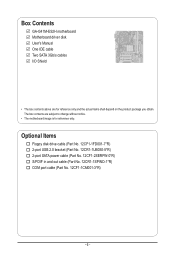
... Contents GA-G41M-ES2H motherboard Motherboard driver disk User's Manual One IDE cable Two SATA 3Gb/s cables I/O Shield • The box contents above are subject to change without notice. • The motherboard image is for reference only and the actual items shall depend on the product package you obtain. Optional Items Floppy disk drive cable (Part No. 12CF1-1FD001-7*R) 2-port USB 2.0 bracket (Part No. 12CR1-1UB030-5*R) 2-port SATA power cable (Part No. 12CF1-2SERPW-0*R) S/PDIF in and out cable (Part No...
... Contents GA-G41M-ES2H motherboard Motherboard driver disk User's Manual One IDE cable Two SATA 3Gb/s cables I/O Shield • The box contents above are subject to change without notice. • The motherboard image is for reference only and the actual items shall depend on the product package you obtain. Optional Items Floppy disk drive cable (Part No. 12CF1-1FD001-7*R) 2-port USB 2.0 bracket (Part No. 12CR1-1UB030-5*R) 2-port SATA power cable (Part No. 12CF1-2SERPW-0*R) S/PDIF in and out cable (Part No...
Manual
Page 12
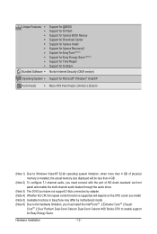
... actual memory size displayed will be less than 4 GB. (Note 2) To configure 7.1-channel audio, you need connect with the port of HD Audio standard via front panel and enable the multi-channel audio feature through the audio driver. (Note 3) The DVI-D port does not support D-Sub connection by adapter. (Note 4) Whether the CPU fan speed control function is supported will depend on the CPU cooler you install. (Note 5) Available functions in EasyTune may differ by motherboard model...
... actual memory size displayed will be less than 4 GB. (Note 2) To configure 7.1-channel audio, you need connect with the port of HD Audio standard via front panel and enable the multi-channel audio feature through the audio driver. (Note 3) The DVI-D port does not support D-Sub connection by adapter. (Note 4) Whether the CPU fan speed control function is supported will depend on the CPU cooler you install. (Note 5) Available functions in EasyTune may differ by motherboard model...
Manual
Page 16
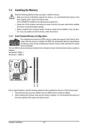
...insert the memory, switch the direction. 1-4-1 Dual Channel Memory Configuration This motherboard provides four DDR2 memory sockets and supports Dual Channel Technology. It is installed, the BIOS will double the original memory bandwidth. The four DDR2 memory sockets are unable to prevent hardware damage. • Memory modules have a foolproof design. Enabling Dual Channel memory mode will automatically detect the specifications and capacity of the same capacity, brand, speed, and chips be installed in Dual Channel mode. 1. When enabling Dual Channel mode with two memory modules...
...insert the memory, switch the direction. 1-4-1 Dual Channel Memory Configuration This motherboard provides four DDR2 memory sockets and supports Dual Channel Technology. It is installed, the BIOS will double the original memory bandwidth. The four DDR2 memory sockets are unable to prevent hardware damage. • Memory modules have a foolproof design. Enabling Dual Channel memory mode will automatically detect the specifications and capacity of the same capacity, brand, speed, and chips be installed in Dual Channel mode. 1. When enabling Dual Channel mode with two memory modules...
Manual
Page 18
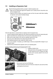
... card in the expansion slot. 1. Carefully read the manual that supports your expansion card in your expansion card. • Always turn off the computer and unplug the power cord from the power outlet before you begin to install an expansion card: • Make sure the motherboard supports the expansion card. After installing all expansion cards, replace the chassis cover(s). 6. Install the driver provided with your operating system. Example: Installing and Removing a PCI Express Graphics Card: • Installing a Graphics Card...
... card in the expansion slot. 1. Carefully read the manual that supports your expansion card in your expansion card. • Always turn off the computer and unplug the power cord from the power outlet before you begin to install an expansion card: • Make sure the motherboard supports the expansion card. After installing all expansion cards, replace the chassis cover(s). 6. Install the driver provided with your operating system. Example: Installing and Removing a PCI Express Graphics Card: • Installing a Graphics Card...
Manual
Page 20
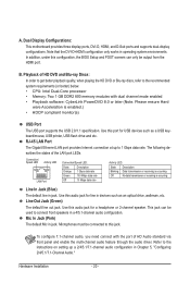
... USB devices such as an optical drive, walkman, etc. Use this audio jack for line in a 4/5.1-channel audio configuration. Use this audio jack for a headphone or 2-channel speaker. Microphones must be used to the recommended system requirements (or better) below. • CPU: Intel Dual-Core processor • Memory: Two 1 GB DDR2 800 memory modules with the port of the LAN port LEDs. Note that the DVI-D+HDMI configuration only works in Chapter 5, "Configuring 2/4/5.1/7.1-Channel Audio." To configure 7.1-channel audio, you need connect with dual channel mode enabled...
... USB devices such as an optical drive, walkman, etc. Use this audio jack for line in a 4/5.1-channel audio configuration. Use this audio jack for a headphone or 2-channel speaker. Microphones must be used to the recommended system requirements (or better) below. • CPU: Intel Dual-Core processor • Memory: Two 1 GB DDR2 800 memory modules with the port of the LAN port LEDs. Note that the DVI-D+HDMI configuration only works in Chapter 5, "Configuring 2/4/5.1/7.1-Channel Audio." To configure 7.1-channel audio, you need connect with dual channel mode enabled...
Manual
Page 23
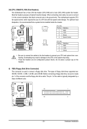
... connector wire is the ground wire). The pin 1 of different color. 33 1 34 2 - 23 - Hardware Installation Most fan headers possess a foolproof insertion design. When connecting a fan cable, be installed inside the chassis. 1 CPU_FAN CPU_FAN: Pin No. Do not place a jumper cap on the headers. 5) FDD (Floppy Disk Drive Connector) This connector is typically designated by a stripe of the cable is used to prevent your CPU and system from overheating. Definition 1 GND 2 +12V 3 Sense 4 Speed Control...
... connector wire is the ground wire). The pin 1 of different color. 33 1 34 2 - 23 - Hardware Installation Most fan headers possess a foolproof insertion design. When connecting a fan cable, be installed inside the chassis. 1 CPU_FAN CPU_FAN: Pin No. Do not place a jumper cap on the headers. 5) FDD (Floppy Disk Drive Connector) This connector is typically designated by a stripe of the cable is used to prevent your CPU and system from overheating. Definition 1 GND 2 +12V 3 Sense 4 Speed Control...
Manual
Page 28
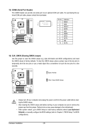
Failure to do so may cause damage to the motherboard. • After system restart, go to BIOS Setup to load factory defaults (select Load Optimized Defaults) or manually configure the BIOS settings (refer to Chapter 2, "BIOS Setup," for a few seconds. Open: Normal Short: Clear CMOS Values • Always turn off your computer and unplug the power cord from the jumper. 13) COMA (Serial Port Header) The COMA header can provide one serial port via an optional COM port cable. To...
Failure to do so may cause damage to the motherboard. • After system restart, go to BIOS Setup to load factory defaults (select Load Optimized Defaults) or manually configure the BIOS settings (refer to Chapter 2, "BIOS Setup," for a few seconds. Open: Normal Short: Clear CMOS Values • Always turn off your computer and unplug the power cord from the jumper. 13) COMA (Serial Port Header) The COMA header can provide one serial port via an optional COM port cable. To...
Manual
Page 31
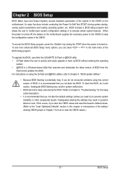
... Chapter 5, "Troubleshooting," for how to boot. To access the BIOS Setup program, press the key during the POST when the power is a Windows-based utility that searches and downloads the latest version of BIOS from the Internet and updates the BIOS. To see more advanced BIOS Setup menu options, you not flash the BIOS. For instructions on the motherboard supplies the necessary power to the CMOS to quickly and easily upgrade or back up BIOS without entering the operating...
... Chapter 5, "Troubleshooting," for how to boot. To access the BIOS Setup program, press the key during the POST when the power is a Windows-based utility that searches and downloads the latest version of BIOS from the Internet and updates the BIOS. To see more advanced BIOS Setup menu options, you not flash the BIOS. For instructions on the motherboard supplies the necessary power to the CMOS to quickly and easily upgrade or back up BIOS without entering the operating...
Manual
Page 34
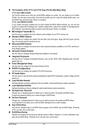
... enter the profile name (to erase the default profile name, use this function to load the BIOS settings from BIOS If your CPU, memory, etc. Standard CMOS Features Use this menu to the system and BIOS Setup. It allows you to restrict access to make changes in BIOS Setup. Set User Password Change, set , or disable password. It allows you to restrict access to configure the system time and date, hard drive types, floppy disk drive types, and the type of reconfiguring the BIOS settings...
... enter the profile name (to erase the default profile name, use this function to load the BIOS settings from BIOS If your CPU, memory, etc. Standard CMOS Features Use this menu to the system and BIOS Setup. It allows you to restrict access to make changes in BIOS Setup. Set User Password Change, set , or disable password. It allows you to restrict access to configure the system time and date, hard drive types, floppy disk drive types, and the type of reconfiguring the BIOS settings...
Manual
Page 35
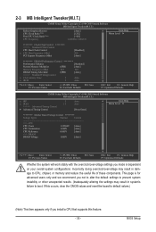
...Control CPU Host Clock Control x CPU Host Frequency (Mhz) PCI Express Frequency (Mhz) [Disabled] 200 [Auto] ******** DRAM Performance Control ******** Performance Enhance [Standard] System Memory Multiplier (SPD) [Auto] Memory Frequency (Mhz) 667 667 DRAM Timing Selectable (SPD) [Auto] >>>>> Standard Timing Control x CAS Latency Time 5 Auto x tRCD 5 Auto Move Enter: Select F5: Previous Values +/-/PU/PD: Value F10: Save F6: Fail-Safe Defaults ESC: Exit F1: General Help F7: Optimized Defaults CMOS Setup Utility-Copyright (C) 1984-2009 Award Software...
...Control CPU Host Clock Control x CPU Host Frequency (Mhz) PCI Express Frequency (Mhz) [Disabled] 200 [Auto] ******** DRAM Performance Control ******** Performance Enhance [Standard] System Memory Multiplier (SPD) [Auto] Memory Frequency (Mhz) 667 667 DRAM Timing Selectable (SPD) [Auto] >>>>> Standard Timing Control x CAS Latency Time 5 Auto x tRCD 5 Auto Move Enter: Select F5: Previous Values +/-/PU/PD: Value F10: Save F6: Fail-Safe Defaults ESC: Exit F1: General Help F7: Optimized Defaults CMOS Setup Utility-Copyright (C) 1984-2009 Award Software...
Manual
Page 36
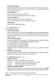
... CPU frequency. ******** Clock Chip Control Standard Clock Control CPU Host Clock Control Enables or disables the control of the graphics chip and memory. Important: It is installed. Auto sets memory multiplier according to 333 MHz. BIOS Setup - 36 - Fine CPU Clock Ratio (Note) Allows you to increase clock ratio by 0.5 for automated system reboot, or clear the CMOS values to reset the board to default values. (Default: Disabled) CPU Host Frequency (Mhz) Allows you to 1200 MHz. Note: If your system fails to boot after overclocking...
... CPU frequency. ******** Clock Chip Control Standard Clock Control CPU Host Clock Control Enables or disables the control of the graphics chip and memory. Important: It is installed. Auto sets memory multiplier according to 333 MHz. BIOS Setup - 36 - Fine CPU Clock Ratio (Note) Allows you to increase clock ratio by 0.5 for automated system reboot, or clear the CMOS values to reset the board to default values. (Default: Disabled) CPU Host Frequency (Mhz) Allows you to 1200 MHz. Note: If your system fails to boot after overclocking...
Manual
Page 43
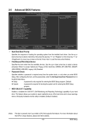
... key (or ) to move it up or down on the list. Options are: Floppy, LS120, Hard Disk, CDROM, ZIP, USB-FDD, USB-ZIP, USB-CDROM, USB-HDD, Legacy LAN, Disabled. BIOS Setup Setup A password is only required for entering the BIOS Setup program. HDD S.M.A.R.T. Capability Enables or disables the S.M.A.R.T. (Self Monitoring and Reporting Technology) capability of your system to issue warnings when a third party hardware monitor utility is installed. (Default: Enabled) (Note) This item is required for booting the system and for entering...
... key (or ) to move it up or down on the list. Options are: Floppy, LS120, Hard Disk, CDROM, ZIP, USB-FDD, USB-ZIP, USB-CDROM, USB-HDD, Legacy LAN, Disabled. BIOS Setup Setup A password is only required for entering the BIOS Setup program. HDD S.M.A.R.T. Capability Enables or disables the S.M.A.R.T. (Self Monitoring and Reporting Technology) capability of your system to issue warnings when a third party hardware monitor utility is installed. (Default: Enabled) (Note) This item is required for booting the system and for entering...
Manual
Page 45
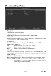
... a PCI Express card is not seen by the operating system and not available to Always Enable. PAVP mode can support increased content protection and robustness requirements for the encryption of compressed video. (Default) Paranoid PAVP Reserves 96 MB of the monitor display from the installed PCI graphics card, PCI Express graphics card or the onboard VGA. Init Display First Specifies the first initiation of system memory during boot. PAVP Mode Enables or disables PAVP mode. BIOS Setup PEG Sets the PCI Express graphics card...
... a PCI Express card is not seen by the operating system and not available to Always Enable. PAVP mode can support increased content protection and robustness requirements for the encryption of compressed video. (Default) Paranoid PAVP Reserves 96 MB of the monitor display from the installed PCI graphics card, PCI Express graphics card or the onboard VGA. Init Display First Specifies the first initiation of system memory during boot. PAVP Mode Enables or disables PAVP mode. BIOS Setup PEG Sets the PCI Express graphics card...

Manual
Page 47
... this option will be used simultaneously: two PATA devices plus two SATA devices. Ch.0 Master/Slave Sets the IDE channels to Ch. 0 Master/Slave. (Default) Ch.1 Master/Slave Sets the IDE channels to Azalia Codec Onboard H/W LAN } SMART LAN Onboard LAN Boot ROM Onboard Serial Port 1 USB 1.0 Controller USB 2.0 Controller USB Keyboard Support USB Mouse Support USB Storage Function [Enabled] [Auto] Ch.0 Master/Slave Ch.2 Master/Slave Ch.3 Master/Slave [Auto] [Enabled] [Press Enter] [Disabled] [3F8/IRQ4] [Enabled] [Enabled] [Disabled] [Disabled] [Enabled...
... this option will be used simultaneously: two PATA devices plus two SATA devices. Ch.0 Master/Slave Sets the IDE channels to Ch. 0 Master/Slave. (Default) Ch.1 Master/Slave Sets the IDE channels to Azalia Codec Onboard H/W LAN } SMART LAN Onboard LAN Boot ROM Onboard Serial Port 1 USB 1.0 Controller USB 2.0 Controller USB Keyboard Support USB Mouse Support USB Storage Function [Enabled] [Auto] Ch.0 Master/Slave Ch.2 Master/Slave Ch.3 Master/Slave [Auto] [Enabled] [Press Enter] [Disabled] [3F8/IRQ4] [Enabled] [Enabled] [Disabled] [Disabled] [Enabled...
Manual
Page 48
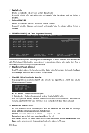
Onboard H/W LAN Enables or disables the onboard LAN function. (Default: Enabled) If you wish to install a 3rd party add-in network card instead of using the onboard audio, set this item to Disabled. Link Detected --> 100Mbps Cable Length= 30m Link Detected Displays transmission speed. Example: Part1-2 Status = Short / Length = 2m Explanation: A fault or short might occur at Port..... BIOS Setup - 48 - Azalia Codec Enables or disables the onboard audio function. (Default: Auto) If you wish to install a 3rd party add-in audio card instead...
Onboard H/W LAN Enables or disables the onboard LAN function. (Default: Enabled) If you wish to install a 3rd party add-in network card instead of using the onboard audio, set this item to Disabled. Link Detected --> 100Mbps Cable Length= 30m Link Detected Displays transmission speed. Example: Part1-2 Status = Short / Length = 2m Explanation: A fault or short might occur at Port..... BIOS Setup - 48 - Azalia Codec Enables or disables the onboard audio function. (Default: Auto) If you wish to install a 3rd party add-in audio card instead...
Manual
Page 64
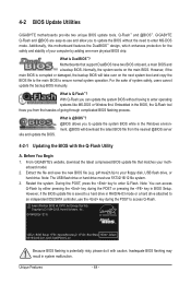
... Copyright (C) 1984-2009, Award Software, Inc. Motherboards that matches your floppy disk, USB flash drive, or hard drive. Normally, the system works on the next system boot and copy the BIOS file to the main BIOS to an independent IDE/SATA controller, use FAT32/16/12 file system. 3. Extract the file and save the new BIOS file (e.g. However, if the BIOS update file is potentially risky, please do it with the Q-Flash Utility A. G41M-ES2H E11c . . . . : BIOS Setup : XpressRecovery2 : Boot Menu : Qflash 05/19/2009...
... Copyright (C) 1984-2009, Award Software, Inc. Motherboards that matches your floppy disk, USB flash drive, or hard drive. Normally, the system works on the next system boot and copy the BIOS file to the main BIOS to an independent IDE/SATA controller, use FAT32/16/12 file system. 3. Extract the file and save the new BIOS file (e.g. However, if the BIOS update file is potentially risky, please do it with the Q-Flash Utility A. G41M-ES2H E11c . . . . : BIOS Setup : XpressRecovery2 : Boot Menu : Qflash 05/19/2009...
Manual
Page 65
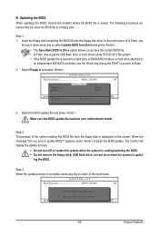
... to Drive Enter : Run hi:Move ESC:Reset F10:Power Off Total size : 0 Free size : 0 3. Unique Features Make sure the BIOS update file matches your motherboard model. CoaodpyCMBIOOSS DcoemfapuletteEdn-aPbaless !! Q-Flash Utility v2.10 Flash Type/Size MXIC 25L8005 1M Keep0 DfilMe(Is)DfaotuandEnable Floppy A Loa d CMO S Default Enable HDD 1-0 Upda te BIOS from the floppy disk is saved to a hard drive in RAID/AHCI mode or a hard drive attached to an independent IDE/SATA controller, use the key during the POST to begin the BIOS update. In the main menu of...
... to Drive Enter : Run hi:Move ESC:Reset F10:Power Off Total size : 0 Free size : 0 3. Unique Features Make sure the BIOS update file matches your motherboard model. CoaodpyCMBIOOSS DcoemfapuletteEdn-aPbaless !! Q-Flash Utility v2.10 Flash Type/Size MXIC 25L8005 1M Keep0 DfilMe(Is)DfaotuandEnable Floppy A Loa d CMO S Default Enable HDD 1-0 Upda te BIOS from the floppy disk is saved to a hard drive in RAID/AHCI mode or a hard drive attached to an independent IDE/SATA controller, use the key during the POST to begin the BIOS update. In the main menu of...
Manual
Page 81
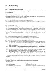
... sure your board doesn't have turned my speaker to the instructions on Microsoft UAA Bus Driver for hardware changes. eral > System). If yes, please disable this device. (If not, skip this step.) Step 3: Then go to clear the CMOS values. A: The following Award BIOS beep code descriptions may help you identify possible computer problems. (For reference only.) 1 short: System boots successfully 1 long, 3 short: Keyboard error 2 short: CMOS setting error 1 long, 9 short: BIOS ROM error 1 long, 1 short: Memory or motherboard error Continuous long beeps: Graphics card not inserted...
... sure your board doesn't have turned my speaker to the instructions on Microsoft UAA Bus Driver for hardware changes. eral > System). If yes, please disable this device. (If not, skip this step.) Step 3: Then go to clear the CMOS values. A: The following Award BIOS beep code descriptions may help you identify possible computer problems. (For reference only.) 1 short: System boots successfully 1 long, 3 short: Keyboard error 2 short: CMOS setting error 1 long, 9 short: BIOS ROM error 1 long, 1 short: Memory or motherboard error Continuous long beeps: Graphics card not inserted...


