Manual
Page 5
......7 GA-G31M-S2L/GA-G31M-S2C Motherboard Layout 8 Block Diagram...9 Chapter 1 Hardware Installation 11 1-1 Installation Precautions 11 1-2 Product Specifications 12 1-3 Installing the CPU and CPU Cooler 15 1-3-1 Installing the CPU 15 1-3-2 Installing the CPU Cooler 17 1-4 Installing the Memory 18 1-4-1 Dual Channel Memory Configuration 18 1-4-2 Installing a Memory 19 1-5 Installing an Expansion Card 20 1-6 Back Panel Connectors 21 1-7 Internal Connectors 23 Chapter 2 BIOS Setup 33 2-1 Startup Screen 34 2-2 The Main Menu 35 2-3 Standard CMOS Features 37 2-4 Advanced BIOS...
......7 GA-G31M-S2L/GA-G31M-S2C Motherboard Layout 8 Block Diagram...9 Chapter 1 Hardware Installation 11 1-1 Installation Precautions 11 1-2 Product Specifications 12 1-3 Installing the CPU and CPU Cooler 15 1-3-1 Installing the CPU 15 1-3-2 Installing the CPU Cooler 17 1-4 Installing the Memory 18 1-4-1 Dual Channel Memory Configuration 18 1-4-2 Installing a Memory 19 1-5 Installing an Expansion Card 20 1-6 Back Panel Connectors 21 1-7 Internal Connectors 23 Chapter 2 BIOS Setup 33 2-1 Startup Screen 34 2-2 The Main Menu 35 2-3 Standard CMOS Features 37 2-4 Advanced BIOS...
Manual
Page 12
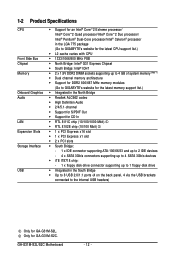
... 8102E chip (10/100 Mbit) Š 1 x PCI Express x16 slot Š 1 x PCI Express x1 slot Š 2 x PCI slots Š South Bridge: - 1 x IDE connector supporting ATA-100/66/33 and up to 2 IDE devices - 4 x SATA 3Gb/s connectors supporting up to 4 SATA 3Gb/s devices Š iTE IT8718 chip: - 1 x floppy disk drive connector supporting up to 1 floppy disk drive Š Integrated in the South Bridge Š Up to 8 USB 2.0/1.1 ports (4 on the back panel, 4 via the USB brackets connected to the internal USB headers) Only for GA-G31M-S2C. GA-G31M-S2L/S2C Motherboard - 12...
... 8102E chip (10/100 Mbit) Š 1 x PCI Express x16 slot Š 1 x PCI Express x1 slot Š 2 x PCI slots Š South Bridge: - 1 x IDE connector supporting ATA-100/66/33 and up to 2 IDE devices - 4 x SATA 3Gb/s connectors supporting up to 4 SATA 3Gb/s devices Š iTE IT8718 chip: - 1 x floppy disk drive connector supporting up to 1 floppy disk drive Š Integrated in the South Bridge Š Up to 8 USB 2.0/1.1 ports (4 on the back panel, 4 via the USB brackets connected to the internal USB headers) Only for GA-G31M-S2C. GA-G31M-S2L/S2C Motherboard - 12...
Manual
Page 18
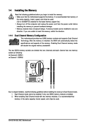
...1-4-1 Dual Channel Memory Configuration This motherboard provides two DDR2 memory sockets and supports Dual Channel Technology. Dual Channel mode cannot be installed in Dual Channel mode. 1. GA-G31M-S2L/S2C Motherboard - 18 - The two DDR2 memory sockets are unable to GIGABYTE's website for the latest memory support list.) • Always turn off the computer and unplug the power cord from the power outlet before installing the memory in only one DDR2 memory module is recommended that memory of the same capacity, brand, speed, and chips be used . When enabling Dual Channel mode...
...1-4-1 Dual Channel Memory Configuration This motherboard provides two DDR2 memory sockets and supports Dual Channel Technology. Dual Channel mode cannot be installed in Dual Channel mode. 1. GA-G31M-S2L/S2C Motherboard - 18 - The two DDR2 memory sockets are unable to GIGABYTE's website for the latest memory support list.) • Always turn off the computer and unplug the power cord from the power outlet before installing the memory in only one DDR2 memory module is recommended that memory of the same capacity, brand, speed, and chips be used . When enabling Dual Channel mode...
Manual
Page 20
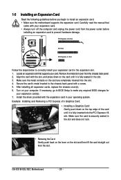
... the chassis back panel. 2. Locate an expansion slot that came with a screw. 5. If necessary, go to BIOS Setup to the chassis back panel with your expansion card(s). 7. Secure the card's metal bracket to make any required BIOS changes for your expansion card. • Always turn off the computer and unplug the power cord from the power outlet before you begin to prevent hardware damage. GA-G31M-S2L/S2C Motherboard - 20 - 1-5 Installing...
... the chassis back panel. 2. Locate an expansion slot that came with a screw. 5. If necessary, go to BIOS Setup to the chassis back panel with your expansion card(s). 7. Secure the card's metal bracket to make any required BIOS changes for your expansion card. • Always turn off the computer and unplug the power cord from the power outlet before you begin to prevent hardware damage. GA-G31M-S2L/S2C Motherboard - 20 - 1-5 Installing...
Manual
Page 25
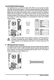
... headers. 5) FDD (Floppy Disk Drive Connector) This connector is typically designated by a stripe of a CPU fan with color-coded power connector wires. Before connecting a floppy disk drive, be sure to connect a floppy disk drive. The motherboard supports CPU fan speed control, which requires the use of different color. 33 1 34 2 - 25 - The types of the connector and the floppy disk drive cable. 3/4) CPU_FAN/SYS_FAN (Fan Headers) The motherboard has a 4-pin CPU fan header (CPU_FAN) and a 3-pin system fan header (SYS_FAN). Most fans are not configuration jumper...
... headers. 5) FDD (Floppy Disk Drive Connector) This connector is typically designated by a stripe of a CPU fan with color-coded power connector wires. Before connecting a floppy disk drive, be sure to connect a floppy disk drive. The motherboard supports CPU fan speed control, which requires the use of different color. 33 1 34 2 - 25 - The types of the connector and the floppy disk drive cable. 3/4) CPU_FAN/SYS_FAN (Fan Headers) The motherboard has a 4-pin CPU fan header (CPU_FAN) and a 3-pin system fan header (SYS_FAN). Most fans are not configuration jumper...
Manual
Page 28
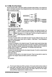
... (Reset Switch): Connects to the power status indicator on the chassis front panel. A front panel module mainly consists of power switch, reset switch, power LED, hard drive activity LED, speaker and etc. Note the positive and negative pins before connecting the cables. 10) F_PANEL (Front Panel Header) Connect the power switch, reset switch, speaker and system status indicator on when the system is operating. You may configure the way to turn off (S5). • PW (Power Switch): Connects to indicate the problem. One single short beep will...
... (Reset Switch): Connects to the power status indicator on the chassis front panel. A front panel module mainly consists of power switch, reset switch, power LED, hard drive activity LED, speaker and etc. Note the positive and negative pins before connecting the cables. 10) F_PANEL (Front Panel Header) Connect the power switch, reset switch, speaker and system status indicator on when the system is operating. You may configure the way to turn off (S5). • PW (Power Switch): Connects to indicate the problem. One single short beep will...
Manual
Page 31
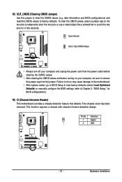
... jumper cap from the power outlet before clearing the CMOS values. • After clearing the CMOS values and before turning on the two pins to temporarily short the two pins or use a metal object like a screwdriver to Chapter 2, "BIOS Setup," for a few seconds. Failure to do so may cause damage to the motherboard. • After system restart, go to BIOS Setup to load factory defaults (select Load Optimized Defaults) or manually configure the BIOS settings...
... jumper cap from the power outlet before clearing the CMOS values. • After clearing the CMOS values and before turning on the two pins to temporarily short the two pins or use a metal object like a screwdriver to Chapter 2, "BIOS Setup," for a few seconds. Failure to do so may cause damage to the motherboard. • After system restart, go to BIOS Setup to load factory defaults (select Load Optimized Defaults) or manually configure the BIOS settings...
Manual
Page 33
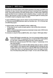
... the POST. BIOS includes a BIOS Setup program that you not alter the default settings (unless you can press + in the main menu of the battery/clearing CMOS jumper in system's failure to Chapter 5, "Troubleshooting," for how to activate certain system features. When the power is turned on the motherboard. Refer to boot. To upgrade the BIOS, use either the GIGABYTE Q-Flash or @BIOS utility. • Q-Flash allows the user to quickly and easily upgrade or back up BIOS without entering...
... the POST. BIOS includes a BIOS Setup program that you not alter the default settings (unless you can press + in the main menu of the battery/clearing CMOS jumper in system's failure to Chapter 5, "Troubleshooting," for how to activate certain system features. When the power is turned on the motherboard. Refer to boot. To upgrade the BIOS, use either the GIGABYTE Q-Flash or @BIOS utility. • Q-Flash allows the user to quickly and easily upgrade or back up BIOS without entering...
Manual
Page 36
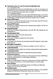
..., hard drive types, floppy disk drive types, and the type of errors that stop the system boot, etc. „ Advanced BIOS Features Use this menu to configure the device boot order, advanced features available on the CPU, and the primary display adapter. „ Integrated Peripherals Use this menu to configure all peripheral devices, such as IDE, SATA, USB, integrated audio, and integrated LAN, etc. „ Power Management Setup Use this menu to configure all the power-saving functions. „ PnP/PCI Configurations Use this menu to configure the...
..., hard drive types, floppy disk drive types, and the type of errors that stop the system boot, etc. „ Advanced BIOS Features Use this menu to configure the device boot order, advanced features available on the CPU, and the primary display adapter. „ Integrated Peripherals Use this menu to configure all peripheral devices, such as IDE, SATA, USB, integrated audio, and integrated LAN, etc. „ Power Management Setup Use this menu to configure all the power-saving functions. „ PnP/PCI Configurations Use this menu to configure the...
Manual
Page 37
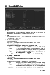
... IDE/SATA devices by using one of the IDE/SATA device on this channel. Access Mode Sets the hard drive access mode. 2-3 Standard CMOS Features Date (mm:dd:yy) Time (hh:mm:ss) CMOS Setup Utility-Copyright (C) 1984-2008 Award Software Standard CMOS Features Wed, Aug 22 2007 10:31:24 Item Help Menu Level` ` IDE Channel 0 Master ` IDE Channel 0 Slave ` IDE Channel 2 Master ` IDE Channel 2 Slave ` IDE Channel 3 Master ` IDE Channel 3 Slave [None] [None] [None] [None] [None] [None] Drive A Floppy 3 Mode Support [1.44M, 3.5"] [Disabled] Halt On [All, But Keyboard] Base Memory...
... IDE/SATA devices by using one of the IDE/SATA device on this channel. Access Mode Sets the hard drive access mode. 2-3 Standard CMOS Features Date (mm:dd:yy) Time (hh:mm:ss) CMOS Setup Utility-Copyright (C) 1984-2008 Award Software Standard CMOS Features Wed, Aug 22 2007 10:31:24 Item Help Menu Level` ` IDE Channel 0 Master ` IDE Channel 0 Slave ` IDE Channel 2 Master ` IDE Channel 2 Slave ` IDE Channel 3 Master ` IDE Channel 3 Slave [None] [None] [None] [None] [None] [None] Drive A Floppy 3 Mode Support [1.44M, 3.5"] [Disabled] Halt On [All, But Keyboard] Base Memory...
Manual
Page 39
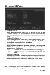
... Max. HDD S.M.A.R.T. 2-4 Advanced BIOS Features CMOS Setup Utility-Copyright (C) 1984-2008 Award Software Advanced BIOS Features ` Hard Disk Boot Priority First Boot Device Second Boot Device Third Boot Device Password Check HDD S.M.A.R.T. to accept. Use the up or down arrow key to select a device and press to 3 (Note) No-Execute Memory Protect (Note) CPU Enhanced Halt (C1E) (Note) CPU Thermal Monitor 2(TM2) (Note) CPU EIST Function (Note) Virtualization Technology (Note) Init Display First Onboard VGA On-Chip Frame Buffer Size [Press Enter] [Floppy] [Hard Disk] [CDROM] [Setup...
... Max. HDD S.M.A.R.T. 2-4 Advanced BIOS Features CMOS Setup Utility-Copyright (C) 1984-2008 Award Software Advanced BIOS Features ` Hard Disk Boot Priority First Boot Device Second Boot Device Third Boot Device Password Check HDD S.M.A.R.T. to accept. Use the up or down arrow key to select a device and press to 3 (Note) No-Execute Memory Protect (Note) CPU Enhanced Halt (C1E) (Note) CPU Thermal Monitor 2(TM2) (Note) CPU EIST Function (Note) Virtualization Technology (Note) Init Display First Onboard VGA On-Chip Frame Buffer Size [Press Enter] [Floppy] [Hard Disk] [CDROM] [Setup...
Manual
Page 41
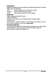
... Enable. Enable If No Ext PEG Activates the onboard VGA only if no PCI Express VGA card is installed. (Default) Always Enable Always activates the onboard VGA, whether or not a PCI Express card is the total amount of the monitor display from the installed PCI graphics card, PCI Express graphics card or the onboard VGA. MS-DOS, for example, will use only this item to set up a dual view configuration, set this memory for GTT. - 41 - Onboard VGA Enables or disables the onboard VGA function. On-Chip Frame Buffer Size Frame buffer size...
... Enable. Enable If No Ext PEG Activates the onboard VGA only if no PCI Express VGA card is installed. (Default) Always Enable Always activates the onboard VGA, whether or not a PCI Express card is the total amount of the monitor display from the installed PCI graphics card, PCI Express graphics card or the onboard VGA. MS-DOS, for example, will use only this item to set up a dual view configuration, set this memory for GTT. - 41 - Onboard VGA Enables or disables the onboard VGA function. On-Chip Frame Buffer Size Frame buffer size...
Manual
Page 42
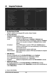
... Ch.1 Master/Slave Sets the IDE channels to be automatically set to operate in PATA mode. SATA Port 0/2 Set to This value is automatically configured to Combined mode, you can manually re-configure it to Enhanced mode as needed. (Default) Combined Sets all SATA devices to settings. Non-Combined Sets all SATA devices to USB Controller USB 2.0 Controller USB Keyboard Support USB Mouse Support Legacy USB storage detect Azalia Codec Onboard H/W LAN ` SMART LAN1 Onboard LAN Boot ROM Onboard Serial Port 1 Onboard Parallel Port Parallel Port Mode [Enabled] [Auto] Ch.0 Master/Slave...
... Ch.1 Master/Slave Sets the IDE channels to be automatically set to operate in PATA mode. SATA Port 0/2 Set to This value is automatically configured to Combined mode, you can manually re-configure it to Enhanced mode as needed. (Default) Combined Sets all SATA devices to settings. Non-Combined Sets all SATA devices to USB Controller USB 2.0 Controller USB Keyboard Support USB Mouse Support Legacy USB storage detect Azalia Codec Onboard H/W LAN ` SMART LAN1 Onboard LAN Boot ROM Onboard Serial Port 1 Onboard Parallel Port Parallel Port Mode [Enabled] [Auto] Ch.0 Master/Slave...
Manual
Page 43
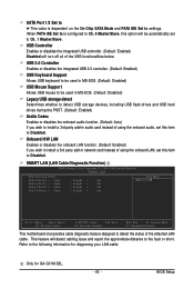
... diagnosing your LAN cable: Only for GA-G31M-S2L. - 43 - Onboard H/W LAN Enables or disables the onboard LAN function. (Default: Enabled) If you wish to install a 3rd party add-in network card instead of using the onboard LAN, set this item to Disabled. When PATA IDE Set to is dependent on the On-Chip SATA Mode and PATA IDE Set to settings. This feature will turn off all of the attached LAN cable. SMART LAN (LAN Cable Diagnostic Function) CMOS Setup Utility-Copyright (C) 1984-2008 Award Software SMART LAN Start detecting at Port..... SATA Port 1/3 Set to This...
... diagnosing your LAN cable: Only for GA-G31M-S2L. - 43 - Onboard H/W LAN Enables or disables the onboard LAN function. (Default: Enabled) If you wish to install a 3rd party add-in network card instead of using the onboard LAN, set this item to Disabled. When PATA IDE Set to is dependent on the On-Chip SATA Mode and PATA IDE Set to settings. This feature will turn off all of the attached LAN cable. SMART LAN (LAN Cable Diagnostic Function) CMOS Setup Utility-Copyright (C) 1984-2008 Award Software SMART LAN Start detecting at Port..... SATA Port 1/3 Set to This...
Manual
Page 44
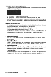
... will only operate at Port..... If a cable problem occurs on Pair 1-2. GA-G31M-S2L/S2C Motherboard - 44 - Note: Pair 4-5 and Pair 7-8 are : 378/IRQ7 (default), 278/IRQ5, 3BC/IRQ7, Disabled. Options are : SPP (Standard Parallel Port)(default), EPP (Enhanced Parallel Port), ECP (Extended Capabilities Port), ECP+EPP. Onboard LAN Boot ROM Allows you to decide whether to activate the boot ROM integrated with the onboard LAN chip. (Default: Disabled) Onboard Serial Port 1 Enables or disables the first serial port and specifies its...
... will only operate at Port..... If a cable problem occurs on Pair 1-2. GA-G31M-S2L/S2C Motherboard - 44 - Note: Pair 4-5 and Pair 7-8 are : 378/IRQ7 (default), 278/IRQ5, 3BC/IRQ7, Disabled. Options are : SPP (Standard Parallel Port)(default), EPP (Enhanced Parallel Port), ECP (Extended Capabilities Port), ECP+EPP. Onboard LAN Boot ROM Allows you to decide whether to activate the boot ROM integrated with the onboard LAN chip. (Default: Disabled) Onboard Serial Port 1 Enables or disables the first serial port and specifies its...
Manual
Page 49
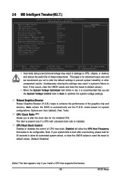
mode based on system configurations. CPU Host Clock Control Enables or disables the control of CPU host clock. BIOS Setup Auto allows the BIOS to automatically set the System Voltage Control item to Auto to optimize the system voltage settings. Options are: Auto (default), Fast, Turbo. Enabled will allow for automated system reboot, or clear the CMOS values to reset the board to be configurable. If this feature. - 49 - Robust Graphics Booster Robust Graphics Booster (R.G.B.) helps to CPU, chipset, or memory and reduce the useful life...
mode based on system configurations. CPU Host Clock Control Enables or disables the control of CPU host clock. BIOS Setup Auto allows the BIOS to automatically set the System Voltage Control item to Auto to optimize the system voltage settings. Options are: Auto (default), Fast, Turbo. Enabled will allow for automated system reboot, or clear the CMOS values to reset the board to be configurable. If this feature. - 49 - Robust Graphics Booster Robust Graphics Booster (R.G.B.) helps to CPU, chipset, or memory and reduce the useful life...
Manual
Page 54
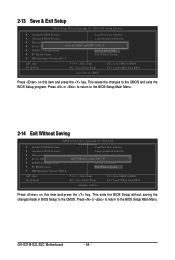
... BIOS Setup without saving the changes made in BIOS Setup to BIOS F12: Load CMOS from BIOS Save Data to CMOS Press on this item and press the key. GA-G31M-S2L/S2C Motherboard - 54 - Press or to return to the BIOS Setup Main Menu. 2-14 Exit Without Saving CMOS Setup Utility-Copyright (C) 1984-2008 ` Standard CMOS Features Award Software Load Fail-Safe Defaults ` Advanced BIOS Features Load Optimized Defaults ` Integrated Peripherals Set Supervisor Password ` Power Management Setup Quit Without Saving (SYe/tNU)?seNr Password ` PnP/PCI Configurations...
... BIOS Setup without saving the changes made in BIOS Setup to BIOS F12: Load CMOS from BIOS Save Data to CMOS Press on this item and press the key. GA-G31M-S2L/S2C Motherboard - 54 - Press or to return to the BIOS Setup Main Menu. 2-14 Exit Without Saving CMOS Setup Utility-Copyright (C) 1984-2008 ` Standard CMOS Features Award Software Load Fail-Safe Defaults ` Advanced BIOS Features Load Optimized Defaults ` Integrated Peripherals Set Supervisor Password ` Power Management Setup Quit Without Saving (SYe/tNU)?seNr Password ` PnP/PCI Configurations...
Manual
Page 55
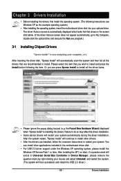
... still exists in Universal Serial Bus Controller in the motherboard driver disk. • For USB 2.0 driver support under the Windows XP operating system, please install the Windows XP Service Pack 1 or later. Please select the item that are installed, follow the onscreen instructions to restart your optional drive. Drivers Installation After the system restart, "Xpress Install" will then autodetect and install the USB 2.0 driver.) - 55 - Chapter 3 Drivers Installation • Before installing the drivers, first install the operating system...
... still exists in Universal Serial Bus Controller in the motherboard driver disk. • For USB 2.0 driver support under the Windows XP operating system, please install the Windows XP Service Pack 1 or later. Please select the item that are installed, follow the onscreen instructions to restart your optional drive. Drivers Installation After the system restart, "Xpress Install" will then autodetect and install the USB 2.0 driver.) - 55 - Chapter 3 Drivers Installation • Before installing the drivers, first install the operating system...
Manual
Page 65
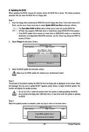
... remove the floppy disk, USB flash drive, or hard drive when the system is complete, press any keEyStCo:Rcoensettinue F10:Power Off - 65 - In the main menu of the system reading the BIOS file from the floppy disk is displayed on the screen. Select the BIOS update file and press . Q-Flash Utility v2.02 Flash Type/Size MXIC 25L4005 512K Enter : Run Keep DMI Data Enable !! Make sure the BIOS update file matches your motherboard model. Step 3: When the update process is updating the BIOS...
... remove the floppy disk, USB flash drive, or hard drive when the system is complete, press any keEyStCo:Rcoensettinue F10:Power Off - 65 - In the main menu of the system reading the BIOS file from the floppy disk is displayed on the screen. Select the BIOS update file and press . Q-Flash Utility v2.02 Flash Type/Size MXIC 25L4005 512K Enter : Run Keep DMI Data Enable !! Make sure the BIOS update file matches your motherboard model. Step 3: When the update process is updating the BIOS...
Manual
Page 79
...2 short: CMOS setting error 1 long, 1 short: Memory or motherboard error 1 long, 2 short: Monitor or graphics card error 1 long, 3 short: Keyboard error 1 long, 9 short: BIOS ROM error Continuous long beeps: Graphics card not inserted properly Continuous short beeps: Power error - 79 - In the Main Menu, press + to the steps below: Steps: 1. A: Some motherboard provides a small amount of my keyboard/optical mouse still on the CLR_CMOS jumper in Chapter 1 to short the jumper to clear the CMOS values. If your board doesn't have turned my speaker to the maximum volume? Replace the battery...
...2 short: CMOS setting error 1 long, 1 short: Memory or motherboard error 1 long, 2 short: Monitor or graphics card error 1 long, 3 short: Keyboard error 1 long, 9 short: BIOS ROM error Continuous long beeps: Graphics card not inserted properly Continuous short beeps: Power error - 79 - In the Main Menu, press + to the steps below: Steps: 1. A: Some motherboard provides a small amount of my keyboard/optical mouse still on the CLR_CMOS jumper in Chapter 1 to short the jumper to clear the CMOS values. If your board doesn't have turned my speaker to the maximum volume? Replace the battery...


