Manual
Page 1
GA-G31M-S2L/ GA-G31M-S2C LGA775 socket motherboard for Intel® CoreTM processor family/ Intel® Pentium® processor family/Intel® Celeron® processor family User's Manual Rev. 1103 12ME-G31MS2L-1103R
GA-G31M-S2L/ GA-G31M-S2C LGA775 socket motherboard for Intel® CoreTM processor family/ Intel® Pentium® processor family/Intel® Celeron® processor family User's Manual Rev. 1103 12ME-G31MS2L-1103R
Manual
Page 3
Motherboard GA-G31M-S2C Jun. 30, 2008 Motherboard GA-G31M-S2C Jun. 30, 2008
Motherboard GA-G31M-S2C Jun. 30, 2008 Motherboard GA-G31M-S2C Jun. 30, 2008
Manual
Page 4
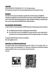
... this manual are legally registered to use GIGABYTE's unique features, read or download the information on/from the Support\Motherboard\Technology Guide page on our website. No part of this manual is protected by GIGABYTE without GIGABYTE's prior written permission. For product-related ...information, check on our website at: http://www.gigabyte.com.tw Identifying Your Motherboard Revision The revision number on how to their respective owners. All...
... this manual are legally registered to use GIGABYTE's unique features, read or download the information on/from the Support\Motherboard\Technology Guide page on our website. No part of this manual is protected by GIGABYTE without GIGABYTE's prior written permission. For product-related ...information, check on our website at: http://www.gigabyte.com.tw Identifying Your Motherboard Revision The revision number on how to their respective owners. All...
Manual
Page 5
Table of Contents Box Contents ...7 OptionalItems...7 GA-G31M-S2L/GA-G31M-S2C Motherboard Layout 8 Block Diagram...9 Chapter 1 Hardware Installation 11 1-1 Installation Precautions 11 1-2 Product Specifications 12 1-3 Installing the CPU and CPU Cooler 15 1-3-1 Installing the CPU 15 1-3-2 Installing ...
Table of Contents Box Contents ...7 OptionalItems...7 GA-G31M-S2L/GA-G31M-S2C Motherboard Layout 8 Block Diagram...9 Chapter 1 Hardware Installation 11 1-1 Installation Precautions 11 1-2 Product Specifications 12 1-3 Installing the CPU and CPU Cooler 15 1-3-1 Installing the CPU 15 1-3-2 Installing ...
Manual
Page 7
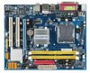
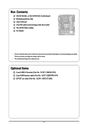
Box Contents GA-G31M-S2L or GA-G31M-S2C motherboard Motherboard driver disk User's Manual One IDE cable and one floppy disk drive cable Two SATA 3Gb/s cables I/O Shield • The box contents above are subject to change without notice. • The motherboard image is for reference only and the actual items shall depend on product package you obtain. The box contents are for reference only. Optional Items 2-port USB 2.0 bracket (Part No. 12CR1-1UB030-51R) 2-port SATA power cable (Part No. 12CF1-2SERPW-01R) S/PDIF out cable (Part No. 12CR1-1SPOUT-02R) - 7 -
Box Contents GA-G31M-S2L or GA-G31M-S2C motherboard Motherboard driver disk User's Manual One IDE cable and one floppy disk drive cable Two SATA 3Gb/s cables I/O Shield • The box contents above are subject to change without notice. • The motherboard image is for reference only and the actual items shall depend on product package you obtain. The box contents are for reference only. Optional Items 2-port USB 2.0 bracket (Part No. 12CR1-1UB030-51R) 2-port SATA power cable (Part No. 12CF1-2SERPW-01R) S/PDIF out cable (Part No. 12CR1-1SPOUT-02R) - 7 -
Manual
Page 8
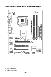
CI CLR_CMOS GA-G31M-S2L/GA-G31M-S2C DDRII1 DDRII2 PWR_LED F_PANEL GA-G31M-S2L/GA-G31M-S2C Motherboard Layout KB_MS ATX_12V LGA775 CPU_FAN COMA LPT LAN VGA R_USB ATX IDE USB AUDIO F_AUDIO RTL8111C RTL8102E PCIE_1 PCIE_16 IT8718 PCI1 CODEC PCI2 CD_IN SPDIF_O FDD Intel® G31 BAT MBIOS SYS_FAN F_USB1F_USB2 Intel® ICH7 SATAII3 SATAII2 SATAII1 SATAII0 Only for GA-G31M-S2C. - 8 - Only for GA-G31M-S2L.
CI CLR_CMOS GA-G31M-S2L/GA-G31M-S2C DDRII1 DDRII2 PWR_LED F_PANEL GA-G31M-S2L/GA-G31M-S2C Motherboard Layout KB_MS ATX_12V LGA775 CPU_FAN COMA LPT LAN VGA R_USB ATX IDE USB AUDIO F_AUDIO RTL8111C RTL8102E PCIE_1 PCIE_16 IT8718 PCI1 CODEC PCI2 CD_IN SPDIF_O FDD Intel® G31 BAT MBIOS SYS_FAN F_USB1F_USB2 Intel® ICH7 SATAII3 SATAII2 SATAII1 SATAII0 Only for GA-G31M-S2C. - 8 - Only for GA-G31M-S2L.
Manual
Page 11
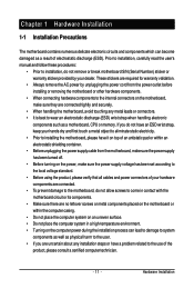
.... • Always remove the AC power by your hardware components are connected tightly and securely. • When handling the motherboard, avoid touching any installation steps or have it on top of an antistatic pad or within the computer casing. • Do ...Before using the product, please verify that all cables and power connectors of your dealer. Chapter 1 Hardware Installation 1-1 Installation Precautions The motherboard contains numerous delicate electronic circuits and components which can lead to damage to system components as well as physical harm to the user....
.... • Always remove the AC power by your hardware components are connected tightly and securely. • When handling the motherboard, avoid touching any installation steps or have it on top of an antistatic pad or within the computer casing. • Do ...Before using the product, please verify that all cables and power connectors of your dealer. Chapter 1 Hardware Installation 1-1 Installation Precautions The motherboard contains numerous delicate electronic circuits and components which can lead to damage to system components as well as physical harm to the user....
Manual
Page 12
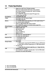
Only for GA-G31M-S2L. GA-G31M-S2L/S2C Motherboard - 12 - 1-2 Product Specifications CPU Front Side Bus Chipset Memory Onboard ...Intel® Pentium® Dual-Core processor/Intel® Celeron® processor in the LGA 775 package (Go to GIGABYTE's website for the latest CPU support list.) Š L2 cache varies with CPU Š 1333/1066/800 MHz...memory (Note 1) Š Dual channel memory architecture Š Support for DDR2 800/667 MHz memory modules (Go to GIGABYTE's website for the latest memory support list.) Š Integrated in the North Bridge Š Realtek ALC662 codec Š ...
Only for GA-G31M-S2L. GA-G31M-S2L/S2C Motherboard - 12 - 1-2 Product Specifications CPU Front Side Bus Chipset Memory Onboard ...Intel® Pentium® Dual-Core processor/Intel® Celeron® processor in the LGA 775 package (Go to GIGABYTE's website for the latest CPU support list.) Š L2 cache varies with CPU Š 1333/1066/800 MHz...memory (Note 1) Š Dual channel memory architecture Š Support for DDR2 800/667 MHz memory modules (Go to GIGABYTE's website for the latest memory support list.) Š Integrated in the North Bridge Š Realtek ALC662 codec Š ...
Manual
Page 14
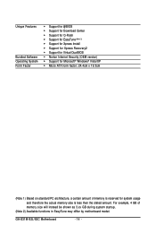
... PC architecture, a certain amount of memory size will instead be shown as 3.xx GB during system startup. (Note 2) Available functions in EasyTune may differ by motherboard model. GA-G31M-S2L/S2C Motherboard - 14 - For example, 4 GB of memory is reserved for system usage and therefore the actual memory size is less than the stated amount.
... PC architecture, a certain amount of memory size will instead be shown as 3.xx GB during system startup. (Note 2) Available functions in EasyTune may differ by motherboard model. GA-G31M-S2L/S2C Motherboard - 14 - For example, 4 GB of memory is reserved for system usage and therefore the actual memory size is less than the stated amount.
Manual
Page 15
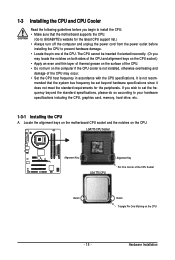
...is not recom- LGA775 CPU Socket Alignment Key LGA 775 CPU Alignment Key Pin One Corner of the CPU. Locate the alignment keys on the motherboard CPU socket and the notches on the CPU - 15 - 1-3 Installing the CPU and CPU Cooler Read the following guidelines before you may occur...; Do not turn off the computer and unplug the power cord from the power outlet before installing the CPU to GIGABYTE's website for the peripherals. Hardware Installation mended that the motherboard supports the CPU. (Go to prevent hardware damage. • Locate the pin one of the CPU Socket Notch...
...is not recom- LGA775 CPU Socket Alignment Key LGA 775 CPU Alignment Key Pin One Corner of the CPU. Locate the alignment keys on the motherboard CPU socket and the notches on the CPU - 15 - 1-3 Installing the CPU and CPU Cooler Read the following guidelines before you may occur...; Do not turn off the computer and unplug the power cord from the power outlet before installing the CPU to GIGABYTE's website for the peripherals. Hardware Installation mended that the motherboard supports the CPU. (Go to prevent hardware damage. • Locate the pin one of the CPU Socket Notch...
Manual
Page 16
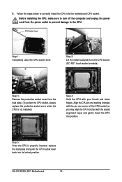
... marking (triangle) with the pin one corner of the CPU socket (or you may align the CPU notches with your thumb and index fingers. GA-G31M-S2L/S2C Motherboard - 16 - Before installing the CPU, make sure to turn off the computer and unplug the power cord from the load plate. (To protect..., always replace the protective socket cover when the CPU is properly inserted, replace the load plate and push the CPU socket lever back into the motherboard CPU socket. Step 2: Lift the metal load plate from the CPU socket. (DO NOT touch socket contacts.) Step 3: Remove the protective socket ...
... marking (triangle) with the pin one corner of the CPU socket (or you may align the CPU notches with your thumb and index fingers. GA-G31M-S2L/S2C Motherboard - 16 - Before installing the CPU, make sure to turn off the computer and unplug the power cord from the load plate. (To protect..., always replace the protective socket cover when the CPU is properly inserted, replace the load plate and push the CPU socket lever back into the motherboard CPU socket. Step 2: Lift the metal load plate from the CPU socket. (DO NOT touch socket contacts.) Step 3: Remove the protective socket ...
Manual
Page 17
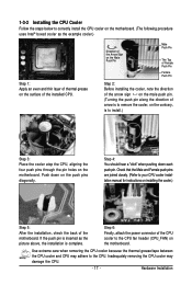
... Hardware Installation Check that the Male and Female push pins are joined closely. (Refer to your CPU cooler installation manual for instructions on the motherboard. Use extreme care when removing the CPU cooler because the thermal grease/tape between the CPU cooler and CPU may damage the CPU. - 17...the push pin is inserted as the example cooler.) Step 1: Apply an even and thin layer of thermal grease on the surface of the motherboard. Inadequately removing the CPU cooler may adhere to the CPU. 1-3-2 Installing the CPU Cooler Follow the steps below to correctly install the CPU ...
... Hardware Installation Check that the Male and Female push pins are joined closely. (Refer to your CPU cooler installation manual for instructions on the motherboard. Use extreme care when removing the CPU cooler because the thermal grease/tape between the CPU cooler and CPU may damage the CPU. - 17...the push pin is inserted as the example cooler.) Step 1: Apply an even and thin layer of thermal grease on the surface of the motherboard. Inadequately removing the CPU cooler may adhere to the CPU. 1-3-2 Installing the CPU Cooler Follow the steps below to correctly install the CPU ...
Manual
Page 18
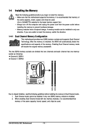
... cannot be used . GA-G31M-S2L/S2C Motherboard - 18 - Enabling Dual Channel memory mode will automatically detect the specifications and capacity of the memory. When enabling Dual Channel mode with two memory modules, it is installed, the BIOS will double the original memory bandwidth. A memory module can be used . (Go to GIGABYTE's website for the...
... cannot be used . GA-G31M-S2L/S2C Motherboard - 18 - Enabling Dual Channel memory mode will automatically detect the specifications and capacity of the memory. When enabling Dual Channel mode with two memory modules, it is installed, the BIOS will double the original memory bandwidth. A memory module can be used . (Go to GIGABYTE's website for the...
Manual
Page 19
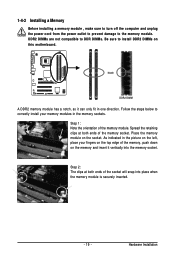
... , make sure to turn off the computer and unplug the power cord from the power outlet to prevent damage to install DDR2 DIMMs on this motherboard. Spread the retaining clips at both ends of the memory, push down on the memory and insert it can only fit in the memory sockets...
... , make sure to turn off the computer and unplug the power cord from the power outlet to prevent damage to install DDR2 DIMMs on this motherboard. Spread the retaining clips at both ends of the memory, push down on the memory and insert it can only fit in the memory sockets...
Manual
Page 20
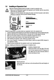
... x1 Slot Follow the steps below to correctly install your computer. Turn on the card are completely inserted into the PCI Express x16 slot. GA-G31M-S2L/S2C Motherboard - 20 - If necessary, go to BIOS Setup to make any required BIOS changes for your operating system. 1-5 Installing an Expansion Card ... and unplug the power cord from the power outlet before you begin to install an expansion card: • Make sure the motherboard supports the expansion card. Install the driver provided with a screw. 5. After installing all expansion cards, replace the chassis cover(s). 6.
... x1 Slot Follow the steps below to correctly install your computer. Turn on the card are completely inserted into the PCI Express x16 slot. GA-G31M-S2L/S2C Motherboard - 20 - If necessary, go to BIOS Setup to make any required BIOS changes for your operating system. 1-5 Installing an Expansion Card ... and unplug the power cord from the power outlet before you begin to install an expansion card: • Make sure the motherboard supports the expansion card. Install the driver provided with a screw. 5. After installing all expansion cards, replace the chassis cover(s). 6.
Manual
Page 21
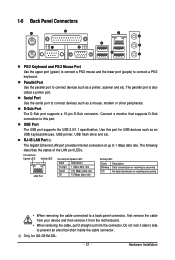
... from the motherboard. • When removing the cable, pull it side to side to connect devices such as a printer, scanner and etc. Only for USB devices such as an USB keyboard/mouse, USB printer, USB flash drive and etc. Parallel Port Use the parallel port to this port for GA-G31M-S2L. - 21 - 1-6 Back...
... from the motherboard. • When removing the cable, pull it side to side to connect devices such as a printer, scanner and etc. Only for USB devices such as an USB keyboard/mouse, USB printer, USB flash drive and etc. Parallel Port Use the parallel port to this port for GA-G31M-S2L. - 21 - 1-6 Back...
Manual
Page 22
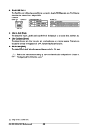
Use this audio jack for GA-G31M-S2C. Microphones must be used to connect front speakers in a 4/5.1-channel audio configuration. Refer to the instructions on setting up to this audio jack for a ... out jack. The following describes the states of the LAN port LEDs. Use this jack. This jack can be connected to 100 Mbps data rate. GA-G31M-S2L/S2C Motherboard - 22 - RJ-45 LAN Port The Fast Ethernet LAN port provides Internet connection at up a 2/4/5.1-channel audio configuration in Chapter 5, "Configuring 2/4/5.1-Channel Audio...
Use this audio jack for GA-G31M-S2C. Microphones must be used to connect front speakers in a 4/5.1-channel audio configuration. Refer to the instructions on setting up to this audio jack for a ... out jack. The following describes the states of the LAN port LEDs. Use this jack. This jack can be connected to 100 Mbps data rate. GA-G31M-S2L/S2C Motherboard - 22 - RJ-45 LAN Port The Fast Ethernet LAN port provides Internet connection at up a 2/4/5.1-channel audio configuration in Chapter 5, "Configuring 2/4/5.1-Channel Audio...
Manual
Page 23
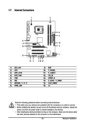
..., make sure your devices are compliant with the connectors you wish to connect. • Before installing the devices, be sure to the connector on the motherboard. - 23 -
..., make sure your devices are compliant with the connectors you wish to connect. • Before installing the devices, be sure to the connector on the motherboard. - 23 -
Manual
Page 24
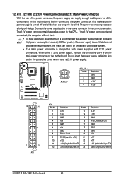
... unbootable system. • The main power connector is turned off and all the components on the motherboard. Do not insert the power supply cable into pins under the protective cover when using a 2x12 ...power supply, remove the protective cover from the main power connector on the motherboard. When using a 2x10 power supply. 3 4 1 2 ATX_12V ATX_12V : Pin No. 1 2 3 4 Definition GND GND +12V +12V 12 24 1 13...5V (Only for 2x12-pinATX) GND (Only for 2x12-pin ATX) GA-G31M-S2L/S2C Motherboard - 24 -
... unbootable system. • The main power connector is turned off and all the components on the motherboard. Do not insert the power supply cable into pins under the protective cover when using a 2x12 ...power supply, remove the protective cover from the main power connector on the motherboard. When using a 2x10 power supply. 3 4 1 2 ATX_12V ATX_12V : Pin No. 1 2 3 4 Definition GND GND +12V +12V 12 24 1 13...5V (Only for 2x12-pinATX) GND (Only for 2x12-pin ATX) GA-G31M-S2L/S2C Motherboard - 24 -
Manual
Page 25
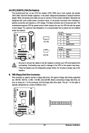
...it is typically designated by a stripe of the cable is recommended that a system fan be sure to connect a floppy disk drive. The motherboard supports CPU fan speed control, which requires the use of the connector and the floppy disk drive cable. Definition 1 1 GND 2 +12V... color. 33 1 34 2 - 25 - Before connecting a floppy disk drive, be installed inside the chassis. 3/4) CPU_FAN/SYS_FAN (Fan Headers) The motherboard has a 4-pin CPU fan header (CPU_FAN) and a 3-pin system fan header (SYS_FAN). For optimum heat dissipation, it in damage to prevent your CPU...
...it is typically designated by a stripe of the cable is recommended that a system fan be sure to connect a floppy disk drive. The motherboard supports CPU fan speed control, which requires the use of the connector and the floppy disk drive cable. Definition 1 1 GND 2 +12V... color. 33 1 34 2 - 25 - Before connecting a floppy disk drive, be installed inside the chassis. 3/4) CPU_FAN/SYS_FAN (Fan Headers) The motherboard has a 4-pin CPU fan header (CPU_FAN) and a 3-pin system fan header (SYS_FAN). For optimum heat dissipation, it in damage to prevent your CPU...


