Manual
Page 1
GA-G31M-S2L/ GA-G31M-S2C LGA775 socket motherboard for Intel® CoreTM processor family/ Intel® Pentium® processor family/Intel® Celeron® processor family User's Manual Rev. 1103 12ME-G31MS2L-1103R
GA-G31M-S2L/ GA-G31M-S2C LGA775 socket motherboard for Intel® CoreTM processor family/ Intel® Pentium® processor family/Intel® Celeron® processor family User's Manual Rev. 1103 12ME-G31MS2L-1103R
Manual
Page 3
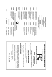
Motherboard GA-G31M-S2C Jun. 30, 2008 Motherboard GA-G31M-S2C Jun. 30, 2008
Motherboard GA-G31M-S2C Jun. 30, 2008 Motherboard GA-G31M-S2C Jun. 30, 2008
Manual
Page 4
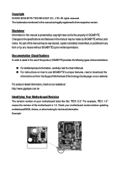
...their respective owners. All rights reserved. The trademarks mentioned in the use GIGABYTE's unique features, read the User's Manual. „ For instructions on your motherboard revision before updating motherboard BIOS, drivers, or when looking for technical information. Documentation Classifications In ... are legally registered to use of this product, GIGABYTE provides the following types of documentations: „ For detailed product information, carefully read or download the information on/from the Support\Motherboard\Technology Guide page on our website. Disclaimer Information...
...their respective owners. All rights reserved. The trademarks mentioned in the use GIGABYTE's unique features, read the User's Manual. „ For instructions on your motherboard revision before updating motherboard BIOS, drivers, or when looking for technical information. Documentation Classifications In ... are legally registered to use of this product, GIGABYTE provides the following types of documentations: „ For detailed product information, carefully read or download the information on/from the Support\Motherboard\Technology Guide page on our website. Disclaimer Information...
Manual
Page 5
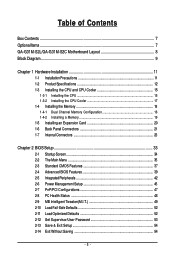
Table of Contents Box Contents ...7 OptionalItems...7 GA-G31M-S2L/GA-G31M-S2C Motherboard Layout 8 Block Diagram...9 Chapter 1 Hardware Installation 11 1-1 Installation Precautions 11 1-2 Product Specifications 12 1-3 Installing the CPU and CPU Cooler 15 1-3-1 Installing the CPU 15 1-3-2 Installing ...
Table of Contents Box Contents ...7 OptionalItems...7 GA-G31M-S2L/GA-G31M-S2C Motherboard Layout 8 Block Diagram...9 Chapter 1 Hardware Installation 11 1-1 Installation Precautions 11 1-2 Product Specifications 12 1-3 Installing the CPU and CPU Cooler 15 1-3-1 Installing the CPU 15 1-3-2 Installing ...
Manual
Page 7
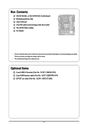
Box Contents GA-G31M-S2L or GA-G31M-S2C motherboard Motherboard driver disk User's Manual One IDE cable and one floppy disk drive cable Two SATA 3Gb/s cables I/O Shield • The box contents above are subject to change without notice. • The motherboard image is for reference only and the actual items shall depend on product package you obtain. Optional Items 2-port USB 2.0 bracket (Part No. 12CR1-1UB030-51R) 2-port SATA power cable (Part No. 12CF1-2SERPW-01R) S/PDIF out cable (Part No. 12CR1-1SPOUT-02R) - 7 - The box contents are for reference only.
Box Contents GA-G31M-S2L or GA-G31M-S2C motherboard Motherboard driver disk User's Manual One IDE cable and one floppy disk drive cable Two SATA 3Gb/s cables I/O Shield • The box contents above are subject to change without notice. • The motherboard image is for reference only and the actual items shall depend on product package you obtain. Optional Items 2-port USB 2.0 bracket (Part No. 12CR1-1UB030-51R) 2-port SATA power cable (Part No. 12CF1-2SERPW-01R) S/PDIF out cable (Part No. 12CR1-1SPOUT-02R) - 7 - The box contents are for reference only.
Manual
Page 8
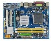
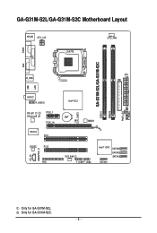
CI CLR_CMOS GA-G31M-S2L/GA-G31M-S2C DDRII1 DDRII2 PWR_LED F_PANEL GA-G31M-S2L/GA-G31M-S2C Motherboard Layout KB_MS ATX_12V LGA775 CPU_FAN COMA LPT LAN VGA R_USB ATX IDE USB AUDIO F_AUDIO RTL8111C RTL8102E PCIE_1 PCIE_16 IT8718 PCI1 CODEC PCI2 CD_IN SPDIF_O FDD Intel® G31 BAT MBIOS SYS_FAN F_USB1F_USB2 Intel® ICH7 SATAII3 SATAII2 SATAII1 SATAII0 Only for GA-G31M-S2C. - 8 - Only for GA-G31M-S2L.
CI CLR_CMOS GA-G31M-S2L/GA-G31M-S2C DDRII1 DDRII2 PWR_LED F_PANEL GA-G31M-S2L/GA-G31M-S2C Motherboard Layout KB_MS ATX_12V LGA775 CPU_FAN COMA LPT LAN VGA R_USB ATX IDE USB AUDIO F_AUDIO RTL8111C RTL8102E PCIE_1 PCIE_16 IT8718 PCI1 CODEC PCI2 CD_IN SPDIF_O FDD Intel® G31 BAT MBIOS SYS_FAN F_USB1F_USB2 Intel® ICH7 SATAII3 SATAII2 SATAII1 SATAII0 Only for GA-G31M-S2C. - 8 - Only for GA-G31M-S2L.
Manual
Page 11
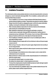
...for warranty validation. • Always remove the AC power by your hardware components are connected. • To prevent damage to the motherboard, do not have an ESD wrist strap, keep your hands dry and first touch a metal object to eliminate static electricity. &#... wrist strap when handling electronic components such as a result of electrostatic discharge (ESD). Chapter 1 Hardware Installation 1-1 Installation Precautions The motherboard contains numerous delicate electronic circuits and components which can lead to damage to system components as well as physical harm to the user. ...
...for warranty validation. • Always remove the AC power by your hardware components are connected. • To prevent damage to the motherboard, do not have an ESD wrist strap, keep your hands dry and first touch a metal object to eliminate static electricity. &#... wrist strap when handling electronic components such as a result of electrostatic discharge (ESD). Chapter 1 Hardware Installation 1-1 Installation Precautions The motherboard contains numerous delicate electronic circuits and components which can lead to damage to system components as well as physical harm to the user. ...
Manual
Page 12
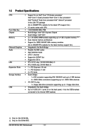
GA-G31M-S2L/S2C Motherboard - 12 - 1-2 Product Specifications CPU Front Side Bus Chipset Memory Onboard Graphics Audio... Intel® Pentium® Dual-Core processor/Intel® Celeron® processor in the LGA 775 package (Go to GIGABYTE's website for the latest CPU support list.) Š L2 cache varies with CPU Š 1333/1066/800 MHz FSB...system memory (Note 1) Š Dual channel memory architecture Š Support for DDR2 800/667 MHz memory modules (Go to GIGABYTE's website for the latest memory support list.) Š Integrated in the North Bridge Š Realtek ALC662 codec Š High...
GA-G31M-S2L/S2C Motherboard - 12 - 1-2 Product Specifications CPU Front Side Bus Chipset Memory Onboard Graphics Audio... Intel® Pentium® Dual-Core processor/Intel® Celeron® processor in the LGA 775 package (Go to GIGABYTE's website for the latest CPU support list.) Š L2 cache varies with CPU Š 1333/1066/800 MHz FSB...system memory (Note 1) Š Dual channel memory architecture Š Support for DDR2 800/667 MHz memory modules (Go to GIGABYTE's website for the latest memory support list.) Š Integrated in the North Bridge Š Realtek ALC662 codec Š High...
Manual
Page 14
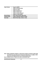
... PC architecture, a certain amount of memory size will instead be shown as 3.xx GB during system startup. (Note 2) Available functions in EasyTune may differ by motherboard model. GA-G31M-S2L/S2C Motherboard - 14 -
... PC architecture, a certain amount of memory size will instead be shown as 3.xx GB during system startup. (Note 2) Available functions in EasyTune may differ by motherboard model. GA-G31M-S2L/S2C Motherboard - 14 -
Manual
Page 15
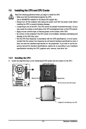
... Notch Triangle Pin One Marking on the computer if the CPU cooler is not recom- mended that the motherboard supports the CPU. (Go to GIGABYTE's website for the peripherals. Locate the alignment keys on the motherboard CPU socket and the notches on the CPU. Hardware Installation If you may occur. • Set the...
... Notch Triangle Pin One Marking on the computer if the CPU cooler is not recom- mended that the motherboard supports the CPU. (Go to GIGABYTE's website for the peripherals. Locate the alignment keys on the motherboard CPU socket and the notches on the CPU. Hardware Installation If you may occur. • Set the...
Manual
Page 16
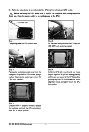
GA-G31M-S2L/S2C Motherboard - 16 - CPU Socket Lever Step 1: Completely raise the CPU socket lever. Align the CPU pin one marking (triangle) with the pin one corner of the ... into position. Step 5: Once the CPU is not installed.) Step 4: Hold the CPU with the socket alignment keys) and gently insert the CPU into the motherboard CPU socket. Follow the steps below to the CPU.
GA-G31M-S2L/S2C Motherboard - 16 - CPU Socket Lever Step 1: Completely raise the CPU socket lever. Align the CPU pin one marking (triangle) with the pin one corner of the ... into position. Step 5: Once the CPU is not installed.) Step 4: Hold the CPU with the socket alignment keys) and gently insert the CPU into the motherboard CPU socket. Follow the steps below to the CPU.
Manual
Page 17
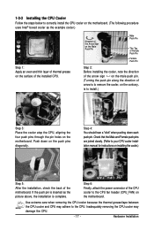
...cooler and CPU may damage the CPU. - 17 - 1-3-2 Installing the CPU Cooler Follow the steps below to correctly install the CPU cooler on the motherboard. (The following procedure uses Intel® boxed cooler as the picture above, the installation is to install.) Step 3: Place the cooler atop the CPU..., aligning the four push pins through the pin holes on the motherboard. Step 4: You should hear a "click" when pushing down on the male push pin. (Turning the push pin along the direction of the installed...
...cooler and CPU may damage the CPU. - 17 - 1-3-2 Installing the CPU Cooler Follow the steps below to correctly install the CPU cooler on the motherboard. (The following procedure uses Intel® boxed cooler as the picture above, the installation is to install.) Step 3: Place the cooler atop the CPU..., aligning the four push pins through the pin holes on the motherboard. Step 4: You should hear a "click" when pushing down on the male push pin. (Turning the push pin along the direction of the installed...
Manual
Page 18
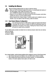
... before installing the memory to insert the memory, switch the direction. 1-4-1 Dual Channel Memory Configuration This motherboard provides two DDR2 memory sockets and supports Dual Channel Technology. When enabling Dual Channel mode with two memory...GIGABYTE's website for the latest memory support list.) • Always turn off the computer and unplug the power cord from the power outlet before installing the memory in only one DDR2 memory module is recommended that memory of the memory. Dual Channel mode cannot be installed in Dual Channel mode. 1. GA-G31M-S2L/S2C Motherboard...
... before installing the memory to insert the memory, switch the direction. 1-4-1 Dual Channel Memory Configuration This motherboard provides two DDR2 memory sockets and supports Dual Channel Technology. When enabling Dual Channel mode with two memory...GIGABYTE's website for the latest memory support list.) • Always turn off the computer and unplug the power cord from the power outlet before installing the memory in only one DDR2 memory module is recommended that memory of the memory. Dual Channel mode cannot be installed in Dual Channel mode. 1. GA-G31M-S2L/S2C Motherboard...
Manual
Page 19
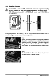
... one direction. Step 1: Note the orientation of the memory, push down on the top edge of the memory module. Place the memory module on this motherboard. Notch DDR2 DIMM A DDR2 memory module has a notch, so it vertically into place when the memory module is securely inserted. - 19 - DDR2 DIMMs are not...
... one direction. Step 1: Note the orientation of the memory, push down on the top edge of the memory module. Place the memory module on this motherboard. Notch DDR2 DIMM A DDR2 memory module has a notch, so it vertically into place when the memory module is securely inserted. - 19 - DDR2 DIMMs are not...
Manual
Page 20
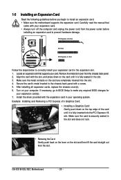
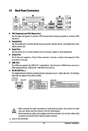
...slot. PCI Express x16 Slot PCI Slot PCI Express x1 Slot Follow the steps below to install an expansion card: • Make sure the motherboard supports the expansion card. Locate an expansion slot that came with your expansion card. • Always turn off the computer and unplug the ...card. Align the card with the slot, and press down on the top edge of the card until it is securely seated in the slot. 3. GA-G31M-S2L/S2C Motherboard - 20 - 1-5 Installing an Expansion Card Read the following guidelines before installing an expansion card to the chassis back panel with a screw. 5. ...
...slot. PCI Express x16 Slot PCI Slot PCI Express x1 Slot Follow the steps below to install an expansion card: • Make sure the motherboard supports the expansion card. Locate an expansion slot that came with your expansion card. • Always turn off the computer and unplug the ...card. Align the card with the slot, and press down on the top edge of the card until it is securely seated in the slot. 3. GA-G31M-S2L/S2C Motherboard - 20 - 1-5 Installing an Expansion Card Read the following guidelines before installing an expansion card to the chassis back panel with a screw. 5. ...
Manual
Page 21
... (purple) to a back panel connector, first remove the cable from your device and then remove it from the motherboard. • When removing the cable, pull it side to side to this port for GA-G31M-S2L. - 21 - Parallel Port Use the parallel port to connect devices such as an USB keyboard/mouse, USB...
... (purple) to a back panel connector, first remove the cable from your device and then remove it from the motherboard. • When removing the cable, pull it side to side to this port for GA-G31M-S2L. - 21 - Parallel Port Use the parallel port to connect devices such as an USB keyboard/mouse, USB...
Manual
Page 22
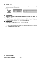
... LAN Port Line In Jack (Blue) The default line in jack. Mic In Jack (Pink) The default Mic in jack. Use this audio jack for GA-G31M-S2C. GA-G31M-S2L/S2C Motherboard - 22 - Line Out Jack (Green) The default line out jack. RJ-45 LAN Port The Fast Ethernet LAN port provides Internet connection at up...
... LAN Port Line In Jack (Blue) The default line in jack. Mic In Jack (Pink) The default Mic in jack. Use this audio jack for GA-G31M-S2C. GA-G31M-S2L/S2C Motherboard - 22 - Line Out Jack (Green) The default line out jack. RJ-45 LAN Port The Fast Ethernet LAN port provides Internet connection at up...
Manual
Page 23
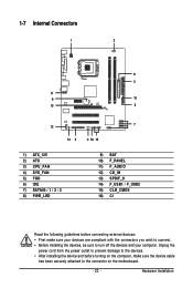
... / 1 / 2 / 3 8) PWR_LED 9) BAT 10) F_PANEL 11) F_AUDIO 12) CD_IN 13) SPDIF_O 14) F_USB1 / F_USB2 15) CLR_CMOS 16) CI Read the following guidelines before turning on the motherboard. - 23 - Hardware Installation Unplug the power cord from the power outlet to prevent damage to the devices. • After installing the device and before connecting...
... / 1 / 2 / 3 8) PWR_LED 9) BAT 10) F_PANEL 11) F_AUDIO 12) CD_IN 13) SPDIF_O 14) F_USB1 / F_USB2 15) CLR_CMOS 16) CI Read the following guidelines before turning on the motherboard. - 23 - Hardware Installation Unplug the power cord from the power outlet to prevent damage to the devices. • After installing the device and before connecting...
Manual
Page 24
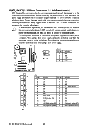
... -12V GND PS_ON(soft On/Off) GND GND GND -5V +5V +5V +5V (Only for 2x12-pinATX) GND (Only for 2x12-pin ATX) GA-G31M-S2L/S2C Motherboard - 24 - Connect the power supply cable to the CPU. If a power supply is used that can lead to an unstable or unbootable system. •...power supply cable into pins under the protective cover when using a 2x12 power supply, remove the protective cover from the main power connector on the motherboard. The power connector possesses a foolproof design. If the 12V power connector is not connected, the computer will not start. • To meet ...
... -12V GND PS_ON(soft On/Off) GND GND GND -5V +5V +5V +5V (Only for 2x12-pinATX) GND (Only for 2x12-pin ATX) GA-G31M-S2L/S2C Motherboard - 24 - Connect the power supply cable to the CPU. If a power supply is used that can lead to an unstable or unbootable system. •...power supply cable into pins under the protective cover when using a 2x12 power supply, remove the protective cover from the main power connector on the motherboard. The power connector possesses a foolproof design. If the 12V power connector is not connected, the computer will not start. • To meet ...
Manual
Page 25
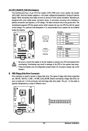
.... A red power connector wire indicates a positive connection and requires a +12V voltage. For optimum heat dissipation, it in damage to connect a floppy disk drive. The motherboard supports CPU fan speed control, which requires the use of the connector and the floppy disk drive cable. Before connecting a floppy disk drive, be installed... connect fan cables to the fan headers to locate pin 1 of a CPU fan with color-coded power connector wires. 3/4) CPU_FAN/SYS_FAN (Fan Headers) The motherboard has a 4-pin CPU fan header (CPU_FAN) and a 3-pin system fan header (SYS_FAN).
.... A red power connector wire indicates a positive connection and requires a +12V voltage. For optimum heat dissipation, it in damage to connect a floppy disk drive. The motherboard supports CPU fan speed control, which requires the use of the connector and the floppy disk drive cable. Before connecting a floppy disk drive, be installed... connect fan cables to the fan headers to locate pin 1 of a CPU fan with color-coded power connector wires. 3/4) CPU_FAN/SYS_FAN (Fan Headers) The motherboard has a 4-pin CPU fan header (CPU_FAN) and a 3-pin system fan header (SYS_FAN).


