Manual
Page 5
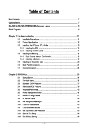
......7 GA-G31M-S2L/GA-G31M-S2C Motherboard Layout 8 Block Diagram...9 Chapter 1 Hardware Installation 11 1-1 Installation Precautions 11 1-2 Product Specifications 12 1-3 Installing the CPU and CPU Cooler 15 1-3-1 Installing the CPU 15 1-3-2 Installing the CPU Cooler 17 1-4 Installing the Memory 18 1-4-1 Dual Channel Memory Configuration 18 1-4-2 Installing a Memory 19 1-5 Installing an Expansion Card 20 1-6 Back Panel Connectors 21 1-7 Internal Connectors 23 Chapter 2 BIOS Setup 33 2-1 Startup Screen 34 2-2 The Main Menu 35 2-3 Standard CMOS Features 37 2-4 Advanced BIOS...
......7 GA-G31M-S2L/GA-G31M-S2C Motherboard Layout 8 Block Diagram...9 Chapter 1 Hardware Installation 11 1-1 Installation Precautions 11 1-2 Product Specifications 12 1-3 Installing the CPU and CPU Cooler 15 1-3-1 Installing the CPU 15 1-3-2 Installing the CPU Cooler 17 1-4 Installing the Memory 18 1-4-1 Dual Channel Memory Configuration 18 1-4-2 Installing a Memory 19 1-5 Installing an Expansion Card 20 1-6 Back Panel Connectors 21 1-7 Internal Connectors 23 Chapter 2 BIOS Setup 33 2-1 Startup Screen 34 2-2 The Main Menu 35 2-3 Standard CMOS Features 37 2-4 Advanced BIOS...
Manual
Page 12
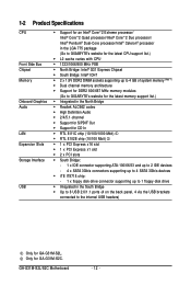
...; RTL 8102E chip (10/100 Mbit) Š 1 x PCI Express x16 slot Š 1 x PCI Express x1 slot Š 2 x PCI slots Š South Bridge: - 1 x IDE connector supporting ATA-100/66/33 and up to 2 IDE devices - 4 x SATA 3Gb/s connectors supporting up to 4 SATA 3Gb/s devices Š iTE IT8718 chip: - 1 x floppy disk drive connector supporting up to 1 floppy disk drive Š Integrated in the South Bridge Š Up to 8 USB 2.0/1.1 ports (4 on the back panel, 4 via the USB brackets connected to the internal USB headers) Only for GA-G31M-S2C. GA-G31M-S2L/S2C Motherboard - 12...
...; RTL 8102E chip (10/100 Mbit) Š 1 x PCI Express x16 slot Š 1 x PCI Express x1 slot Š 2 x PCI slots Š South Bridge: - 1 x IDE connector supporting ATA-100/66/33 and up to 2 IDE devices - 4 x SATA 3Gb/s connectors supporting up to 4 SATA 3Gb/s devices Š iTE IT8718 chip: - 1 x floppy disk drive connector supporting up to 1 floppy disk drive Š Integrated in the South Bridge Š Up to 8 USB 2.0/1.1 ports (4 on the back panel, 4 via the USB brackets connected to the internal USB headers) Only for GA-G31M-S2C. GA-G31M-S2L/S2C Motherboard - 12...
Manual
Page 18
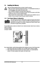
... install the memory: • Make sure that memory of the same capacity, brand, speed, and chips be enabled if only one direction. Dual Channel mode cannot be used . When enabling Dual Channel mode with two memory modules, it is installed, the BIOS will double the original memory bandwidth. A memory module can be used . (Go to GIGABYTE's website for the latest memory support list.) • Always turn off the computer and unplug the power cord from the power...
... install the memory: • Make sure that memory of the same capacity, brand, speed, and chips be enabled if only one direction. Dual Channel mode cannot be used . When enabling Dual Channel mode with two memory modules, it is installed, the BIOS will double the original memory bandwidth. A memory module can be used . (Go to GIGABYTE's website for the latest memory support list.) • Always turn off the computer and unplug the power cord from the power...
Manual
Page 20
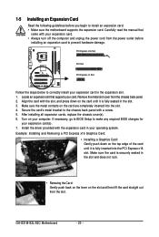
...: Installing and Removing a PCI Express x16 Graphics Card: • Installing a Graphics Card: Gently push down on the slot and then lift the card straight out from the chassis back panel. 2. Remove the metal slot cover from the slot. After installing all expansion cards, replace the chassis cover(s). 6. Turn on the top edge of the card until it is fully seated in the expansion slot. 1. If necessary, go to BIOS Setup to make any required BIOS changes for...
...: Installing and Removing a PCI Express x16 Graphics Card: • Installing a Graphics Card: Gently push down on the slot and then lift the card straight out from the chassis back panel. 2. Remove the metal slot cover from the slot. After installing all expansion cards, replace the chassis cover(s). 6. Turn on the top edge of the card until it is fully seated in the expansion slot. 1. If necessary, go to BIOS Setup to make any required BIOS changes for...
Manual
Page 25
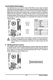
... fan headers to locate pin 1 of the connector and the floppy disk drive cable. Before connecting a floppy disk drive, be installed inside the chassis. A red power connector wire indicates a positive connection and requires a +12V voltage. Overheating may result in the correct orientation. The pin 1 of different color. 33 1 34 2 - 25 - The black connector wire is typically designated by a stripe of the cable is the ground wire. CPU_FAN : Pin No. 3/4) CPU_FAN/SYS_FAN (Fan Headers) The motherboard has a 4-pin CPU fan header (CPU_FAN) and a 3-pin system fan header...
... fan headers to locate pin 1 of the connector and the floppy disk drive cable. Before connecting a floppy disk drive, be installed inside the chassis. A red power connector wire indicates a positive connection and requires a +12V voltage. Overheating may result in the correct orientation. The pin 1 of different color. 33 1 34 2 - 25 - The black connector wire is typically designated by a stripe of the cable is the ground wire. CPU_FAN : Pin No. 3/4) CPU_FAN/SYS_FAN (Fan Headers) The motherboard has a 4-pin CPU fan header (CPU_FAN) and a 3-pin system fan header...
Manual
Page 28
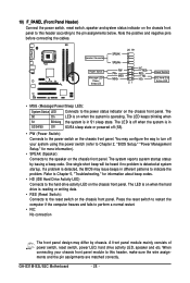
...mainly consists of power switch, reset switch, power LED, hard drive activity LED, speaker and etc. Speaker Connector Power Switch Message LED/ Power/ Sleep LED SPEAK- 20 19 SPEAK+ PWPW+ MSGMSG+ 21 NCRES+ RES- When connecting your system using the power switch (refer to Chapter 2, "BIOS Setup," "Power Management Setup," for information about beep codes. • HD (IDE Hard Drive Activity LED) Connects to the hard drive activity LED on the chassis front panel. HDHD+ Reset Switch IDE Hard Disk Active LED • MSG (Message/Power/Sleep LED): System Status LED Connects to the pin...
...mainly consists of power switch, reset switch, power LED, hard drive activity LED, speaker and etc. Speaker Connector Power Switch Message LED/ Power/ Sleep LED SPEAK- 20 19 SPEAK+ PWPW+ MSGMSG+ 21 NCRES+ RES- When connecting your system using the power switch (refer to Chapter 2, "BIOS Setup," "Power Management Setup," for information about beep codes. • HD (IDE Hard Drive Activity LED) Connects to the hard drive activity LED on the chassis front panel. HDHD+ Reset Switch IDE Hard Disk Active LED • MSG (Message/Power/Sleep LED): System Status LED Connects to the pin...
Manual
Page 31
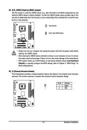
... motherboard. • After system restart, go to BIOS Setup to load factory defaults (select Load Optimized Defaults) or manually configure the BIOS settings (refer to clear the CMOS values (e.g. Pin No. 15) CLR_CMOS (Clearing CMOS Jumper) Use this jumper to Chapter 2, "BIOS Setup," for a few seconds. This function requires a chassis with chassis intrusion detection design. To clear the CMOS values, place a jumper cap on your computer and unplug the power cord from the jumper. date information and BIOS configurations) and reset...
... motherboard. • After system restart, go to BIOS Setup to load factory defaults (select Load Optimized Defaults) or manually configure the BIOS settings (refer to clear the CMOS values (e.g. Pin No. 15) CLR_CMOS (Clearing CMOS Jumper) Use this jumper to Chapter 2, "BIOS Setup," for a few seconds. This function requires a chassis with chassis intrusion detection design. To clear the CMOS values, place a jumper cap on your computer and unplug the power cord from the jumper. date information and BIOS configurations) and reset...
Manual
Page 33
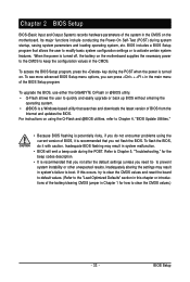
... power is turned on the motherboard supplies the necessary power to the CMOS to keep the configuration values in system malfunction. • BIOS will emit a beep code during system startup, saving system parameters and loading operating system, etc. For instructions on the motherboard. Inadequately altering the settings may result in the CMOS. Inadequate BIOS flashing may result in the CMOS on using the Q-Flash and @BIOS utilities, refer to Chapter 4, "BIOS Update Utilities." • Because BIOS flashing...
... power is turned on the motherboard supplies the necessary power to the CMOS to keep the configuration values in system malfunction. • BIOS will emit a beep code during system startup, saving system parameters and loading operating system, etc. For instructions on the motherboard. Inadequately altering the settings may result in the CMOS. Inadequate BIOS flashing may result in the CMOS on using the Q-Flash and @BIOS utilities, refer to Chapter 4, "BIOS Update Utilities." • Because BIOS flashing...
Manual
Page 36
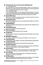
..., hard drive types, floppy disk drive types, and the type of errors that stop the system boot, etc. „ Advanced BIOS Features Use this menu to configure the device boot order, advanced features available on the CPU, and the primary display adapter. „ Integrated Peripherals Use this menu to configure all peripheral devices, such as IDE, SATA, USB, integrated audio, and integrated LAN, etc. „ Power Management Setup Use this menu to configure all changes and the previous settings remain in BIOS Setup. „ Set User Password Change, set , or disable password. First...
..., hard drive types, floppy disk drive types, and the type of errors that stop the system boot, etc. „ Advanced BIOS Features Use this menu to configure the device boot order, advanced features available on the CPU, and the primary display adapter. „ Integrated Peripherals Use this menu to configure all peripheral devices, such as IDE, SATA, USB, integrated audio, and integrated LAN, etc. „ Power Management Setup Use this menu to configure all changes and the previous settings remain in BIOS Setup. „ Set User Password Change, set , or disable password. First...
Manual
Page 37
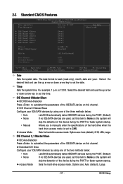
... key to autodetect the parameters of the IDE/SATA device on this channel. Options are : Auto (default), Large. - 37 - Extended IDE Drive Configure your IDE/SATA devices by using one of the two methods below : • Auto • None • Manual Lets BIOS automatically detect IDE/SATA devices during the POST for faster system startup. BIOS Setup Access Mode Sets the hard drive access mode. IDE Channel 2, 3 Master/Slave IDE Auto-Detection Press to autodetect the parameters of the device during the POST. (Default) • None If no IDE/SATA devices...
... key to autodetect the parameters of the IDE/SATA device on this channel. Options are : Auto (default), Large. - 37 - Extended IDE Drive Configure your IDE/SATA devices by using one of the two methods below : • Auto • None • Manual Lets BIOS automatically detect IDE/SATA devices during the POST for faster system startup. BIOS Setup Access Mode Sets the hard drive access mode. IDE Channel 2, 3 Master/Slave IDE Auto-Detection Press to autodetect the parameters of the device during the POST. (Default) • None If no IDE/SATA devices...
Manual
Page 39
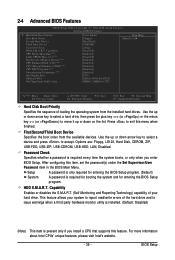
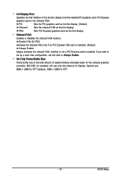
...-Execute Memory Protect (Note) CPU Enhanced Halt (C1E) (Note) CPU Thermal Monitor 2(TM2) (Note) CPU EIST Function (Note) Virtualization Technology (Note) Init Display First Onboard VGA On-Chip Frame Buffer Size [Press Enter] [Floppy] [Hard Disk] [CDROM] [Setup] [Disabled] [Enabled] [Disabled] [Enabled] [Enabled] [Enabled] [Enabled] [Enabled] [PCI] [Enable If No Ext PEG] [8MB+1~2MB for entering the BIOS Setup program. Use the up or down arrow key to select a device and press to exit this item, set the password(s) under the Set Supervisor/User Password item in the BIOS Main Menu...
...-Execute Memory Protect (Note) CPU Enhanced Halt (C1E) (Note) CPU Thermal Monitor 2(TM2) (Note) CPU EIST Function (Note) Virtualization Technology (Note) Init Display First Onboard VGA On-Chip Frame Buffer Size [Press Enter] [Floppy] [Hard Disk] [CDROM] [Setup] [Disabled] [Enabled] [Disabled] [Enabled] [Enabled] [Enabled] [Enabled] [Enabled] [PCI] [Enable If No Ext PEG] [8MB+1~2MB for entering the BIOS Setup program. Use the up or down arrow key to select a device and press to exit this item, set the password(s) under the Set Supervisor/User Password item in the BIOS Main Menu...
Manual
Page 41
On-Chip Frame Buffer Size Frame buffer size is installed. BIOS Setup PEG Sets PCI Express graphics card as the first display. Options are: 8MB+1~2MB for GTT (default), 1MB+1~2MB for display. Init Display First Specifies the first initiation of system memory allocated solely for the onboard graphics controller. MS-DOS, for example, will use only this item to set up a dual view configuration, set this memory for GTT. - 41 - Onboard VGA Enables or disables the onboard VGA function. Enable If No Ext...
On-Chip Frame Buffer Size Frame buffer size is installed. BIOS Setup PEG Sets PCI Express graphics card as the first display. Options are: 8MB+1~2MB for GTT (default), 1MB+1~2MB for display. Init Display First Specifies the first initiation of system memory allocated solely for the onboard graphics controller. MS-DOS, for example, will use only this item to set up a dual view configuration, set this memory for GTT. - 41 - Onboard VGA Enables or disables the onboard VGA function. Enable If No Ext...
Manual
Page 42
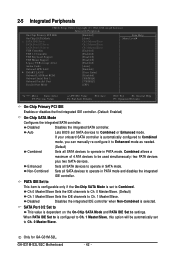
... is configured to Ch. 1 Master/Slave, this option will be used simultaneously: two PATA devices plus two SATA devices. GA-G31M-S2L/S2C Motherboard - 42 - Combined allows a maximum of 4 ATA devices to USB Controller USB 2.0 Controller USB Keyboard Support USB Mouse Support Legacy USB storage detect Azalia Codec Onboard H/W LAN ` SMART LAN1 Onboard LAN Boot ROM Onboard Serial Port 1 Onboard Parallel Port Parallel Port Mode [Enabled] [Auto] Ch.0 Master/Slave Ch.2 Master/Slave Ch.3 Master/Slave [Enabled] [Enabled] [Disabled] [Disabled] [Enabled] [Auto] [Enabled] [Press Enter] [Disabled...
... is configured to Ch. 1 Master/Slave, this option will be used simultaneously: two PATA devices plus two SATA devices. GA-G31M-S2L/S2C Motherboard - 42 - Combined allows a maximum of 4 ATA devices to USB Controller USB 2.0 Controller USB Keyboard Support USB Mouse Support Legacy USB storage detect Azalia Codec Onboard H/W LAN ` SMART LAN1 Onboard LAN Boot ROM Onboard Serial Port 1 Onboard Parallel Port Parallel Port Mode [Enabled] [Auto] Ch.0 Master/Slave Ch.2 Master/Slave Ch.3 Master/Slave [Enabled] [Enabled] [Disabled] [Disabled] [Enabled] [Auto] [Enabled] [Press Enter] [Disabled...
Manual
Page 43
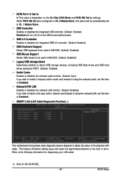
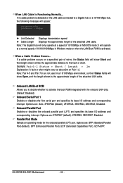
...-in audio card instead of the attached LAN cable. SMART LAN (LAN Cable Diagnostic Function) CMOS Setup Utility-Copyright (C) 1984-2008 Award Software SMART LAN Start detecting at Port..... Onboard H/W LAN Enables or disables the onboard LAN function. (Default: Enabled) If you wish to Disabled. This feature will turn off all of using the onboard audio, set this item to install a 3rd party add-in network card instead of the USB functionalities below. Refer to the fault or short. USB Controller Enables or disables the integrated USB controller. (Default: Enabled) Disabled...
...-in audio card instead of the attached LAN cable. SMART LAN (LAN Cable Diagnostic Function) CMOS Setup Utility-Copyright (C) 1984-2008 Award Software SMART LAN Start detecting at Port..... Onboard H/W LAN Enables or disables the onboard LAN function. (Default: Enabled) If you wish to Disabled. This feature will turn off all of using the onboard audio, set this item to install a 3rd party add-in network card instead of the USB functionalities below. Refer to the fault or short. USB Controller Enables or disables the integrated USB controller. (Default: Enabled) Disabled...
Manual
Page 44
..., 3BC/IRQ7, Disabled. Note: The Gigabit hub will appear: Start detecting at a speed of 10/100Mbps in Windows mode or when the LAN Boot ROM is activated. If a cable problem occurs on a specified pair of the attached LAN cable. Options are : SPP (Standard Parallel Port)(default), EPP (Enhanced Parallel Port), ECP (Extended Capabilities Port), ECP+EPP. GA-G31M-S2L/S2C Motherboard - 44 - If no cable problem is the approximate length of wires, the Status...
..., 3BC/IRQ7, Disabled. Note: The Gigabit hub will appear: Start detecting at a speed of 10/100Mbps in Windows mode or when the LAN Boot ROM is activated. If a cable problem occurs on a specified pair of the attached LAN cable. Options are : SPP (Standard Parallel Port)(default), EPP (Enhanced Parallel Port), ECP (Extended Capabilities Port), ECP+EPP. GA-G31M-S2L/S2C Motherboard - 44 - If no cable problem is the approximate length of wires, the Status...
Manual
Page 49
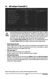
mode based on system configurations. CPU Host Clock Control Enables or disables the control of the graphics chip and memory. 2-9 MB Intelligent Tweaker(M.I.T.) CMOS Setup Utility-Copyright (C) 1984-2008 Award Software MB Intelligent Tweaker(M.I.T.) Robust Graphics Booster CPU Clock Ratio (Note) CPU Host Clock Control x CPU Host Frequency (Mhz) PCI Express Frequency (Mhz) Performance Enhance System Memory Multiplier (SPD) Memory Frequency (Mhz) 533 High Speed DRAM DLL Settings ******** System Voltage Optimized System Voltage Control DDR2 OverVoltage Control FSB OverVoltage Control CPU ...
mode based on system configurations. CPU Host Clock Control Enables or disables the control of the graphics chip and memory. 2-9 MB Intelligent Tweaker(M.I.T.) CMOS Setup Utility-Copyright (C) 1984-2008 Award Software MB Intelligent Tweaker(M.I.T.) Robust Graphics Booster CPU Clock Ratio (Note) CPU Host Clock Control x CPU Host Frequency (Mhz) PCI Express Frequency (Mhz) Performance Enhance System Memory Multiplier (SPD) Memory Frequency (Mhz) 533 High Speed DRAM DLL Settings ******** System Voltage Optimized System Voltage Control DDR2 OverVoltage Control FSB OverVoltage Control CPU ...
Manual
Page 54
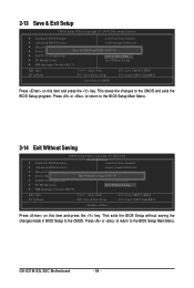
... changes to the CMOS. GA-G31M-S2L/S2C Motherboard - 54 - This exits the BIOS Setup without saving the changes made in BIOS Setup to the CMOS and exits the BIOS Setup program. Press or to return to the BIOS Setup Main Menu. 2-14 Exit Without Saving CMOS Setup Utility-Copyright (C) 1984-2008 ` Standard CMOS Features Award Software Load Fail-Safe Defaults ` Advanced BIOS Features Load Optimized Defaults ` Integrated Peripherals Set Supervisor Password ` Power Management Setup Quit Without Saving (SYe/tNU)?seNr Password ` PnP/PCI Configurations Save & Exit Setup...
... changes to the CMOS. GA-G31M-S2L/S2C Motherboard - 54 - This exits the BIOS Setup without saving the changes made in BIOS Setup to the CMOS and exits the BIOS Setup program. Press or to return to the BIOS Setup Main Menu. 2-14 Exit Without Saving CMOS Setup Utility-Copyright (C) 1984-2008 ` Standard CMOS Features Award Software Load Fail-Safe Defaults ` Advanced BIOS Features Load Optimized Defaults ` Integrated Peripherals Set Supervisor Password ` Power Management Setup Quit Without Saving (SYe/tNU)?seNr Password ` PnP/PCI Configurations Save & Exit Setup...
Manual
Page 55
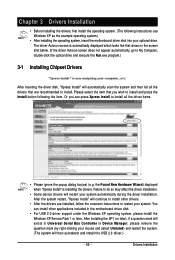
....exe program.) 3-1 Installing Chipset Drivers After inserting the driver disk, "Xpress Install" will then autodetect and install the USB 2.0 driver.) - 55 - You can press Xpress Install to install and press the Install button following instructions use Windows XP as the example operating system.) • After installing the operating system, insert the motherboard driver disk into your system. Failure to do so may affect the driver installation. • Some device drivers will continue to install other applications...
....exe program.) 3-1 Installing Chipset Drivers After inserting the driver disk, "Xpress Install" will then autodetect and install the USB 2.0 driver.) - 55 - You can press Xpress Install to install and press the Install button following instructions use Windows XP as the example operating system.) • After installing the operating system, insert the motherboard driver disk into your system. Failure to do so may affect the driver installation. • Some device drivers will continue to install other applications...
Manual
Page 65
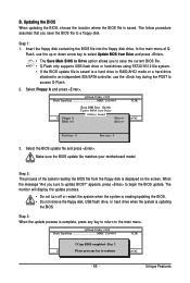
... BIOS file. • Q-Flash only supports USB flash drive or hard drives using FAT32/16/12 file system. • If the BIOS update file is saved to a hard drive in RAID/AHCI mode or a hard drive attached to an independent IDE/SATA controller, use the up or down arrow key to select Update BIOS from Drive Sa0vefilBeI(Os)SfotounDdrive KL:Move ESC:Reset :Power Off Total size : 0 Free size : 0 3. Step 1: 1. Select Floppy A and press . B. Insert the floppy disk containing the BIOS file into the floppy disk drive. Make sure the BIOS update file matches your motherboard model...
... BIOS file. • Q-Flash only supports USB flash drive or hard drives using FAT32/16/12 file system. • If the BIOS update file is saved to a hard drive in RAID/AHCI mode or a hard drive attached to an independent IDE/SATA controller, use the up or down arrow key to select Update BIOS from Drive Sa0vefilBeI(Os)SfotounDdrive KL:Move ESC:Reset :Power Off Total size : 0 Free size : 0 3. Step 1: 1. Select Floppy A and press . B. Insert the floppy disk containing the BIOS file into the floppy disk drive. Make sure the BIOS update file matches your motherboard model...
Manual
Page 79
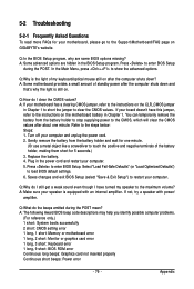
... following Award BIOS beep code descriptions may help you identify possible computer problems. (For reference only.) 1 short: System boots successfully 2 short: CMOS setting error 1 long, 1 short: Memory or motherboard error 1 long, 2 short: Monitor or graphics card error 1 long, 3 short: Keyboard error 1 long, 9 short: BIOS ROM error Continuous long beeps: Graphics card not inserted properly Continuous short beeps: Power error - 79 - Press to the maximum volume? Q: Why is equipped with power/ amplifier. Q: How do I have this jumper, refer to the instructions on the motherboard battery...
... following Award BIOS beep code descriptions may help you identify possible computer problems. (For reference only.) 1 short: System boots successfully 2 short: CMOS setting error 1 long, 1 short: Memory or motherboard error 1 long, 2 short: Monitor or graphics card error 1 long, 3 short: Keyboard error 1 long, 9 short: BIOS ROM error Continuous long beeps: Graphics card not inserted properly Continuous short beeps: Power error - 79 - Press to the maximum volume? Q: Why is equipped with power/ amplifier. Q: How do I have this jumper, refer to the instructions on the motherboard battery...


