Manual
Page 1
GA-G31M-S2L/ GA-G31M-S2C LGA775 socket motherboard for Intel® CoreTM processor family/ Intel® Pentium® processor family/Intel® Celeron® processor family User's Manual Rev. 1103 12ME-G31MS2L-1103R
GA-G31M-S2L/ GA-G31M-S2C LGA775 socket motherboard for Intel® CoreTM processor family/ Intel® Pentium® processor family/Intel® Celeron® processor family User's Manual Rev. 1103 12ME-G31MS2L-1103R
Manual
Page 5
Table of Contents Box Contents ...7 OptionalItems...7 GA-G31M-S2L/GA-G31M-S2C Motherboard Layout 8 Block Diagram...9 Chapter 1 Hardware Installation 11 1-1 Installation Precautions 11 1-2 Product Specifications 12 1-3 Installing the CPU and CPU Cooler 15 1-3-1 Installing the CPU 15 1-3-2 ...
Table of Contents Box Contents ...7 OptionalItems...7 GA-G31M-S2L/GA-G31M-S2C Motherboard Layout 8 Block Diagram...9 Chapter 1 Hardware Installation 11 1-1 Installation Precautions 11 1-2 Product Specifications 12 1-3 Installing the CPU and CPU Cooler 15 1-3-1 Installing the CPU 15 1-3-2 ...
Manual
Page 7
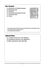
The box contents are for reference only. Box Contents GA-G31M-S2L or GA-G31M-S2C motherboard Motherboard driver disk User's Manual One IDE cable and one floppy disk drive cable Two SATA 3Gb/s cables I/O Shield • The box contents above are subject to change without notice. • The motherboard image is for reference only and the actual items shall depend on product package you obtain. Optional Items 2-port USB 2.0 bracket (Part No. 12CR1-1UB030-51R) 2-port SATA power cable (Part No. 12CF1-2SERPW-01R) S/PDIF out cable (Part No. 12CR1-1SPOUT-02R) - 7 -
The box contents are for reference only. Box Contents GA-G31M-S2L or GA-G31M-S2C motherboard Motherboard driver disk User's Manual One IDE cable and one floppy disk drive cable Two SATA 3Gb/s cables I/O Shield • The box contents above are subject to change without notice. • The motherboard image is for reference only and the actual items shall depend on product package you obtain. Optional Items 2-port USB 2.0 bracket (Part No. 12CR1-1UB030-51R) 2-port SATA power cable (Part No. 12CF1-2SERPW-01R) S/PDIF out cable (Part No. 12CR1-1SPOUT-02R) - 7 -
Manual
Page 8
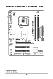
CI CLR_CMOS GA-G31M-S2L/GA-G31M-S2C DDRII1 DDRII2 PWR_LED F_PANEL GA-G31M-S2L/GA-G31M-S2C Motherboard Layout KB_MS ATX_12V LGA775 CPU_FAN COMA LPT LAN VGA R_USB ATX IDE USB AUDIO F_AUDIO RTL8111C RTL8102E PCIE_1 PCIE_16 IT8718 PCI1 CODEC PCI2 CD_IN SPDIF_O FDD Intel® G31 BAT MBIOS SYS_FAN F_USB1F_USB2 Intel® ICH7 SATAII3 SATAII2 SATAII1 SATAII0 Only for GA-G31M-S2C. - 8 - Only for GA-G31M-S2L.
CI CLR_CMOS GA-G31M-S2L/GA-G31M-S2C DDRII1 DDRII2 PWR_LED F_PANEL GA-G31M-S2L/GA-G31M-S2C Motherboard Layout KB_MS ATX_12V LGA775 CPU_FAN COMA LPT LAN VGA R_USB ATX IDE USB AUDIO F_AUDIO RTL8111C RTL8102E PCIE_1 PCIE_16 IT8718 PCI1 CODEC PCI2 CD_IN SPDIF_O FDD Intel® G31 BAT MBIOS SYS_FAN F_USB1F_USB2 Intel® ICH7 SATAII3 SATAII2 SATAII1 SATAII0 Only for GA-G31M-S2C. - 8 - Only for GA-G31M-S2L.
Manual
Page 9
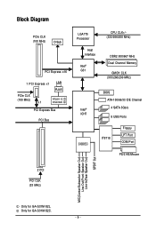
.../Mouse 2 PCI PCI CLK (33 MHz) MIC(Center/Subwoofer Speaker Out) Line-Out(Front Speaker Out) Line-In(Rear Speaker Out) SPDIF Out Only for GA-G31M-S2C. - 9 - Only for GA-G31M-S2L.
.../Mouse 2 PCI PCI CLK (33 MHz) MIC(Center/Subwoofer Speaker Out) Line-Out(Front Speaker Out) Line-In(Rear Speaker Out) SPDIF Out Only for GA-G31M-S2C. - 9 - Only for GA-G31M-S2L.
Manual
Page 12
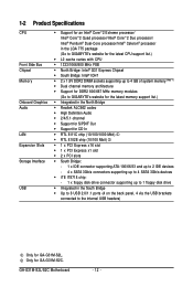
...174; Pentium® Dual-Core processor/Intel® Celeron® processor in the LGA 775 package (Go to GIGABYTE's website for the latest CPU support list.) Š L2 cache varies with CPU Š 1333/1066/800 ...memory (Note 1) Š Dual channel memory architecture Š Support for DDR2 800/667 MHz memory modules (Go to GIGABYTE's website for the latest memory support list.) Š Integrated in the North Bridge Š Realtek ALC662 codec Š... via the USB brackets connected to the internal USB headers) Only for GA-G31M-S2C. Only for GA-G31M-S2L. GA-G31M-S2L/S2C Motherboard - 12 -
...174; Pentium® Dual-Core processor/Intel® Celeron® processor in the LGA 775 package (Go to GIGABYTE's website for the latest CPU support list.) Š L2 cache varies with CPU Š 1333/1066/800 ...memory (Note 1) Š Dual channel memory architecture Š Support for DDR2 800/667 MHz memory modules (Go to GIGABYTE's website for the latest memory support list.) Š Integrated in the North Bridge Š Realtek ALC662 codec Š... via the USB brackets connected to the internal USB headers) Only for GA-G31M-S2C. Only for GA-G31M-S2L. GA-G31M-S2L/S2C Motherboard - 12 -
Manual
Page 14
GA-G31M-S2L/S2C Motherboard - 14 - For example, 4 GB of memory is reserved for system usage and therefore the actual memory size is less than the stated amount. Unique ...
GA-G31M-S2L/S2C Motherboard - 14 - For example, 4 GB of memory is reserved for system usage and therefore the actual memory size is less than the stated amount. Unique ...
Manual
Page 16
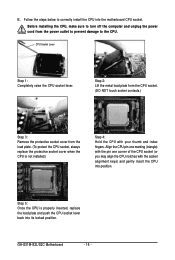
... socket contacts.) Step 3: Remove the protective socket cover from the power outlet to prevent damage to correctly install the CPU into the motherboard CPU socket. GA-G31M-S2L/S2C Motherboard - 16 - Follow the steps below to the CPU. Align the CPU pin one marking (triangle) with the pin one corner of the CPU socket...
... socket contacts.) Step 3: Remove the protective socket cover from the power outlet to prevent damage to correctly install the CPU into the motherboard CPU socket. GA-G31M-S2L/S2C Motherboard - 16 - Follow the steps below to the CPU. Align the CPU pin one marking (triangle) with the pin one corner of the CPU socket...
Manual
Page 18
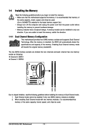
Enabling Dual Channel memory mode will automatically detect the specifications and capacity of the memory. GA-G31M-S2L/S2C Motherboard - 18 - 1-4 Installing the Memory Read the following guidelines before you are divided into two channels and each channel has one direction. It ... Dual Channel mode with two memory modules, it is recommended that the motherboard supports the memory. A memory module can be used . (Go to GIGABYTE's website for the latest memory support list.) • Always turn off the computer and unplug the power cord from the power outlet before installing the...
Enabling Dual Channel memory mode will automatically detect the specifications and capacity of the memory. GA-G31M-S2L/S2C Motherboard - 18 - 1-4 Installing the Memory Read the following guidelines before you are divided into two channels and each channel has one direction. It ... Dual Channel mode with two memory modules, it is recommended that the motherboard supports the memory. A memory module can be used . (Go to GIGABYTE's website for the latest memory support list.) • Always turn off the computer and unplug the power cord from the power outlet before installing the...
Manual
Page 20
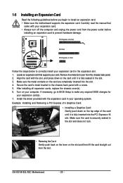
.... • Always turn off the computer and unplug the power cord from the chassis back panel. 2. After installing all expansion cards, replace the chassis cover(s). 6. GA-G31M-S2L/S2C Motherboard - 20 - PCI Express x16 Slot PCI Slot PCI Express x1 Slot Follow the steps below to correctly install your expansion card(s). 7. Secure the card...
.... • Always turn off the computer and unplug the power cord from the chassis back panel. 2. After installing all expansion cards, replace the chassis cover(s). 6. GA-G31M-S2L/S2C Motherboard - 20 - PCI Express x16 Slot PCI Slot PCI Express x1 Slot Follow the steps below to correctly install your expansion card(s). 7. Secure the card...
Manual
Page 21
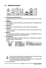
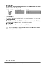
... to 1 Gbps data rate. Use this port. RJ-45 LAN Port The Gigabit Ethernet LAN port provides Internet connection at up to this port for GA-G31M-S2L. - 21 - Connection/ Speed LED Activity LED LAN Port Connection/Speed LED: State Description Orange 1 Gbps data rate Green 100 Mbps data rate Off 10 Mbps...
... to 1 Gbps data rate. Use this port. RJ-45 LAN Port The Gigabit Ethernet LAN port provides Internet connection at up to this port for GA-G31M-S2L. - 21 - Connection/ Speed LED Activity LED LAN Port Connection/Speed LED: State Description Orange 1 Gbps data rate Green 100 Mbps data rate Off 10 Mbps...
Manual
Page 22
...) The default line in jack. Only for line in a 4/5.1-channel audio configuration. Line Out Jack (Green) The default line out jack. GA-G31M-S2L/S2C Motherboard - 22 - Use this audio jack for GA-G31M-S2C. Refer to the instructions on setting up to connect front speakers in devices such as an optical drive, walkman, etc. The following...
...) The default line in jack. Only for line in a 4/5.1-channel audio configuration. Line Out Jack (Green) The default line out jack. GA-G31M-S2L/S2C Motherboard - 22 - Use this audio jack for GA-G31M-S2C. Refer to the instructions on setting up to connect front speakers in devices such as an optical drive, walkman, etc. The following...
Manual
Page 24
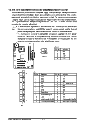
... Definition 3.3V -12V GND PS_ON(soft On/Off) GND GND GND -5V +5V +5V +5V (Only for 2x12-pinATX) GND (Only for 2x12-pin ATX) GA-G31M-S2L/S2C Motherboard - 24 - 1/2) ATX_12V/ATX (2x2 12V Power Connector and 2x12 Main Power Connector) With the use of the power connector, the power supply can supply...
... Definition 3.3V -12V GND PS_ON(soft On/Off) GND GND GND -5V +5V +5V +5V (Only for 2x12-pinATX) GND (Only for 2x12-pin ATX) GA-G31M-S2L/S2C Motherboard - 24 - 1/2) ATX_12V/ATX (2x2 12V Power Connector and 2x12 Main Power Connector) With the use of the power connector, the power supply can supply...
Manual
Page 26
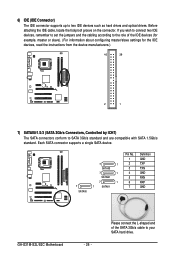
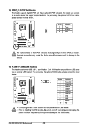
... drives and optical drives. Each SATA connector supports a single SATA device. 7 1 SATAII3 7 1 SATAII2 7 1 7 1 SATAII1 SATAII0 Pin No. 1 2 3 4 5 6 7 Definition GND TXP TXN GND RXN RXP GND GA-G31M-S2L/S2C Motherboard - 26 - Before attaching the IDE cable, locate the foolproof groove on the connector.
... drives and optical drives. Each SATA connector supports a single SATA device. 7 1 SATAII3 7 1 SATAII2 7 1 7 1 SATAII1 SATAII0 Pin No. 1 2 3 4 5 6 7 Definition GND TXP TXN GND RXN RXP GND GA-G31M-S2L/S2C Motherboard - 26 - Before attaching the IDE cable, locate the foolproof groove on the connector.
Manual
Page 28
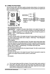
... negative pins before connecting the cables. A front panel module mainly consists of power switch, reset switch, power LED, hard drive activity LED, speaker and etc. GA-G31M-S2L/S2C Motherboard - 28 - Press the reset switch to restart the computer if the computer freezes and fails to the pin assignments below. 10) F_PANEL (Front Panel...
... negative pins before connecting the cables. A front panel module mainly consists of power switch, reset switch, power LED, hard drive activity LED, speaker and etc. GA-G31M-S2L/S2C Motherboard - 28 - Press the reset switch to restart the computer if the computer freezes and fails to the pin assignments below. 10) F_PANEL (Front Panel...
Manual
Page 30
... the USB bracket, be sure to turn off your computer and unplug the power cord from the power outlet to prevent damage to USB 2.0/1.1 specification. GA-G31M-S2L/S2C Motherboard - 30 - Incorrect connection may render the device unusable or even result in . 13) SPDIF_O (S/PDIF Out Header) This header supports digital S/PDIF out. Each...
... the USB bracket, be sure to turn off your computer and unplug the power cord from the power outlet to prevent damage to USB 2.0/1.1 specification. GA-G31M-S2L/S2C Motherboard - 30 - Incorrect connection may render the device unusable or even result in . 13) SPDIF_O (S/PDIF Out Header) This header supports digital S/PDIF out. Each...

Manual
Page 32
GA-G31M-S2L/S2C Motherboard - 32 -
GA-G31M-S2L/S2C Motherboard - 32 -
Manual
Page 34
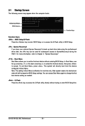
Intel G31 BIOS for G31M-S2L D9a . . . . : BIOS Setup/Q-Flash : XpressRecovery2 : Boot Menu : Qflash 08/21/2007-G31-ICH7-6A79OG0VC-00 Function Keys Function Keys: : BIOS Setup/Q-Flash Press the key ... in BIOS Setup. : Xpress Recovery2 If you to set the first boot device without having to accept. You can be based on BIOS Setup settings. GA-G31M-S2L/S2C Motherboard - 34 - 2-1 Startup Screen The following screen may appear when the computer boots. In Boot Menu, use the up hard drive data using the motherboard...
Intel G31 BIOS for G31M-S2L D9a . . . . : BIOS Setup/Q-Flash : XpressRecovery2 : Boot Menu : Qflash 08/21/2007-G31-ICH7-6A79OG0VC-00 Function Keys Function Keys: : BIOS Setup/Q-Flash Press the key ... in BIOS Setup. : Xpress Recovery2 If you to set the first boot device without having to accept. You can be based on BIOS Setup settings. GA-G31M-S2L/S2C Motherboard - 34 - 2-1 Startup Screen The following screen may appear when the computer boots. In Boot Menu, use the up hard drive data using the motherboard...
Manual
Page 35
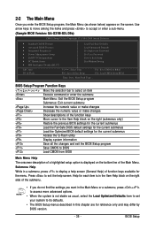
... shown below) appears on the screen. Use arrow keys to move among the items and press to accept or enter a sub-menu. (Sample BIOS Version: GA-G31M-S2L D9a) CMOS Setup Utility-Copyright (C) 1984-2008 Award Software ` Standard CMOS Features ` Advanced BIOS Features ` Integrated Peripherals ` Power Management Setup ` PnP/PCI Configurations ` PC Health...
... shown below) appears on the screen. Use arrow keys to move among the items and press to accept or enter a sub-menu. (Sample BIOS Version: GA-G31M-S2L D9a) CMOS Setup Utility-Copyright (C) 1984-2008 Award Software ` Standard CMOS Features ` Advanced BIOS Features ` Integrated Peripherals ` Power Management Setup ` PnP/PCI Configurations ` PC Health...
Manual
Page 36
It allows you to restrict access to the confirmation message will exit BIOS Setup. (Pressing can also carry out this task.) GA-G31M-S2L/S2C Motherboard - 36 - Pressing to the system and BIOS Setup. It allows you to restrict access to the CMOS and exit BIOS Setup. (Pressing can also ...
It allows you to restrict access to the confirmation message will exit BIOS Setup. (Pressing can also carry out this task.) GA-G31M-S2L/S2C Motherboard - 36 - Pressing to the system and BIOS Setup. It allows you to restrict access to the CMOS and exit BIOS Setup. (Pressing can also ...


